Triton TR 40 - Water pump Pentair - Free user manual and instructions
Find the device manual for free Triton TR 40 Pentair in PDF.
| Product Type | Fiberglass Sand Filter |
| Model | Triton TR 40 |
| Brand | Pentair |
| Filter Area | 0.18 m² (1.92 ft²) |
| Nominal Flow Rate | 144 L/min (38 GPM) at 20 GPM/ft² |
| Maximum Working Pressure | 345 kPa (50 psi) |
| Height Above Sand (X) | 20.9 cm |
| Required Sand Quantity | 79.5 kg (silica sand #20) |
| Required Pea Gravel | 56.8 kg (3-6.35 mm pea gravel) |
| Additional Filter Media | 22.7 kg |
| Dimensions (H × W × D) | 77.5 × 49.5 × 82.6 cm |
| Top Opening Diameter | 15 cm (6 in) - rectangular trapezoidal thread |
| Inlet/Outlet Connection | 2 in NPT |
| Valve | Multiport or 2-position slide valve (not included) |
| Lid Type | Threaded 6 in (after Dec. 1991) |
| Pressure Gauge | Mounted on lid |
| Air Relief | Manual on lid, internal automatic vent |
| Sand Drain | 2 in plug at filter bottom |
| Certification | NSF |
| Warranty | Refer to manual |
Frequently Asked Questions - Triton TR 40 Pentair
User questions about Triton TR 40 Pentair
0 question about this device. Answer the ones you know or ask your own.
Ask a new question about this device
Download the instructions for your Water pump in PDF format for free! Find your manual Triton TR 40 - Pentair and take your electronic device back in hand. On this page are published all the documents necessary for the use of your device. Triton TR 40 by Pentair.
USER MANUAL Triton TR 40 Pentair
FIBERGLASS SAND FILTER
MODELS: TR 40, TR 50, TR 60, TR 100, TR 140, TR 100HD, TR 100C, TR 140C, TR 100C-3, TR 140C-3 and TR 60 with CLEARPRO TECHNOLOGY™
natural_image
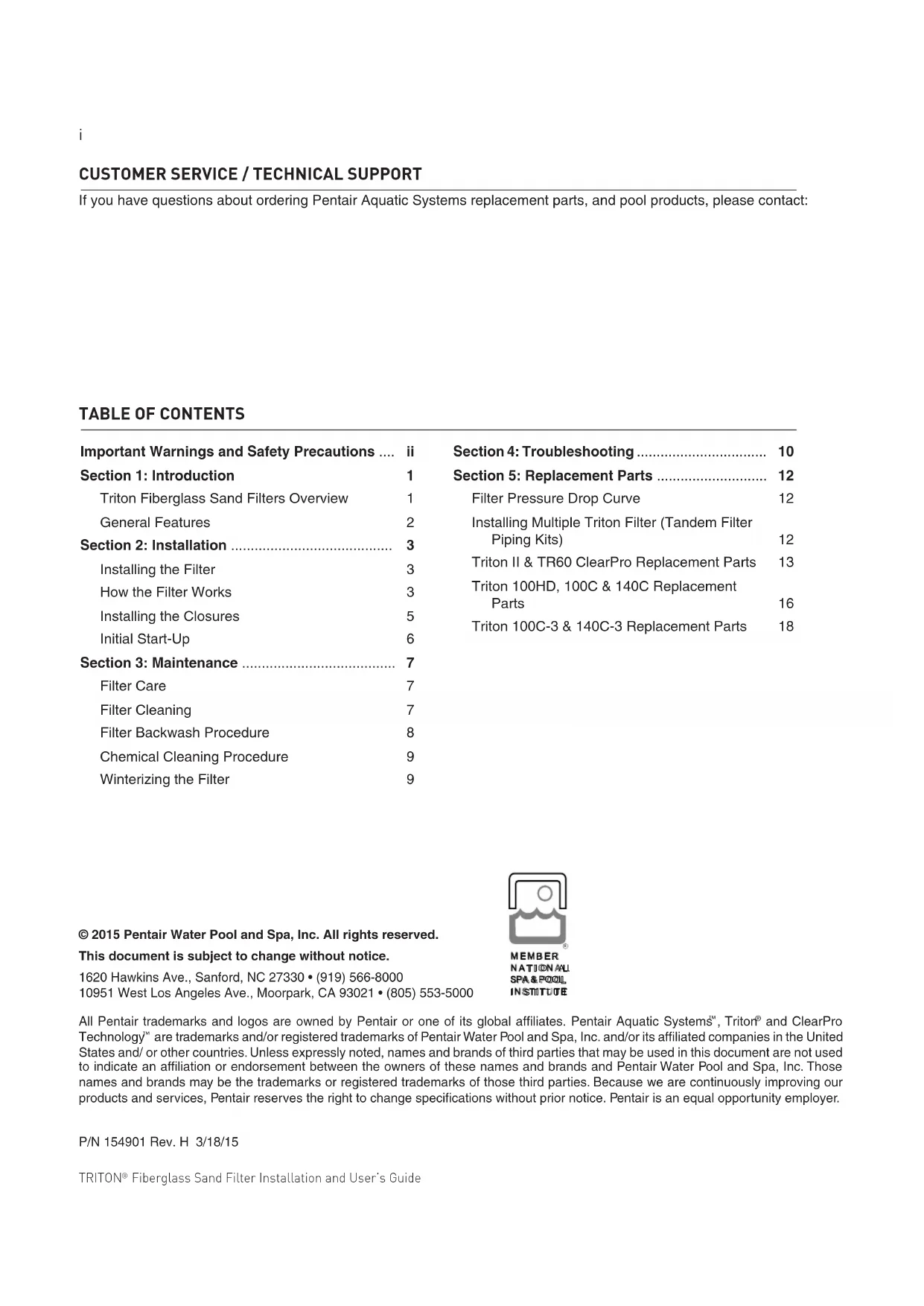
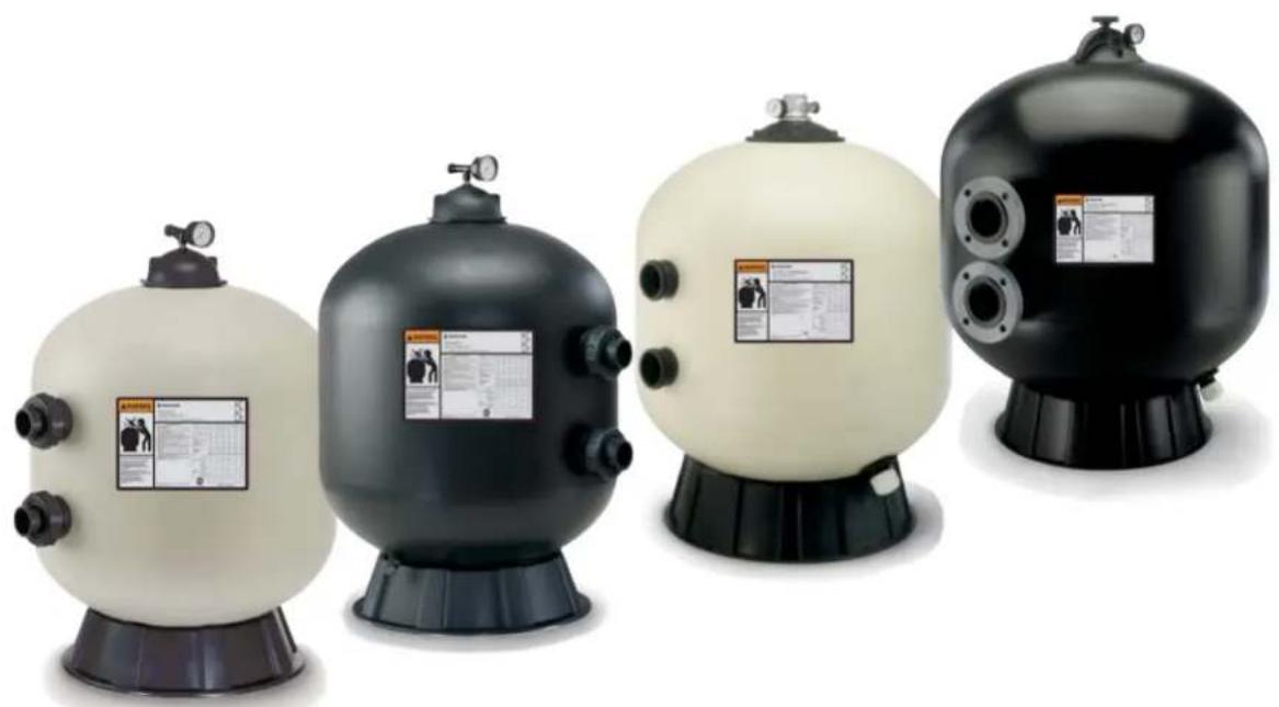
Four industrial pressure vessel models with black and white casing, each featuring a labeled safety warning panel (no visible text or symbols on the vessels themselves)INSTALLATION AND USER'S GUIDE
IMPORTANT SAFETY INSTRUCTIONS READ AND FOLLOW ALL INSTRUCTIONS SAVE THESE INSTRUCTIONS
CUSTOMER SERVICE / TECHNICAL SUPPORT
If you have questions about ordering Pentair Aquatic Systems replacement parts, and pool products, please contact:
TABLE OF CONTENTS
Important Warnings and Safety Precautions .... ii
Section 1: Introduction 1
Triton Fiberglass Sand Filters Overview 1
General Features 2
Section 2: Installation .... 3
Installing the Filter 3
How the Filter Works 3
Installing the Closures 5
Initial Start-Up 6
Section 3: Maintenance 7
Filter Care 7
Filter Cleaning 7
Filter Backwash Procedure 8
Chemical Cleaning Procedure 9
Winterizing the Filter 9
Section 4: Troubleshooting .... 10
Section 5: Replacement Parts ...... 12
Filter Pressure Drop Curve 12
Installing Multiple Triton Filter (Tandem Filter Piping Kits) 12
Triton II & TR60 ClearPro Replacement Parts 13
Triton 100HD, 100C & 140C Replacement Parts 16
Triton 100C-3 & 140C-3 Replacement Parts 18
© 2015 Pentair Water Pool and Spa, Inc. All rights reserved.
This document is subject to change without notice.
1620 Hawkins Ave., Sanford, NC 27330 • (919) 566-8000
10951 West Los Angeles Ave., Moorpark, CA 93021 • (805) 553-5000

MEMBER
NATIONAL
SPA & POOL
INSTITUTE
All Pentair trademarks and logos are owned by Pentair or one of its global affiliates. Pentair Aquatic Systems ^™ , Triton ^® and ClearPro Technology ^™ are trademarks and/or registered trademarks of Pentair Water Pool and Spa, Inc. and/or its affiliated companies in the United States and/or other countries. Unless expressly noted, names and brands of third parties that may be used in this document are not used to indicate an affiliation or endorsement between the owners of these names and brands and Pentair Water Pool and Spa, Inc. Those names and brands may be the trademarks or registered trademarks of those third parties. Because we are continuously improving our products and services, Pentair reserves the right to change specifications without prior notice. Pentair is an equal opportunity employer.
P/N 154901 Rev. H 3/18/15
IMPORTANT WARNING AND SAFETY INSTRUCTIONS

IMPORTANT NOTICE:
This guide provides installation and operation instructions for the Triton® Series Fiberglass Sand Filters. Consult Pentair Water Pool and Spa, Inc. with any questions regarding this equipment.
Attention Installer: This guide contains important information about the installation, operation and safe usage of this product. This information should be given to the owner and/or operator of this equipment after installation or left on or near the filter.
Attention User: This manual contains important information that will help you in operating and maintaining this filter. Please retain it for future reference.
WARNING
Before installing this product, read and follow all warning notices and instructions which are included. Failure to follow safety warnings and instructions can result in severe injury, death, or property damage. Call (800) 831-7133 for additional free copies of these instructions.
Consumer Information and Safety
The Triton Series Sand Filters are designed and manufactured to provide many years of safe and reliable service when installed, operated and maintained according to the information in this manual and the installation codes referred to in later sections. Throughout the manual, safety warnings and cautions are identified by the “⚠️” symbol. Be sure to read and comply with all of the warnings and cautions.
THIS FILTER OPERATES UNDER HIGH PRESSURE
WARNING

When any part of the circulating system, (e.g., closure, pump, filter, valve(s), etc.), is serviced, air can enter the system and become pressurized. Pressurized air can cause the top closure to separate which can result in severe injury, death, or property damage. To avoid this potential hazard, follow these instructions:
- If you are not familiar with your pool filtering system and/or heater:
a. Do NOT attempt to adjust or service without consulting your dealer, or a qualified pool technician.
b. Read the entire Installation & User's Guide before attempting to use, service or adjust the pool filtering system or heater.
- Before repositioning valve(s) and before beginning the assembly, disassembly, or any other service of the circulating system: (A) Turn the pump OFF and shut OFF any automatic controls to ensure the system is NOT inadvertently started during the servicing; (B) open the manual air bleeder valve; (C) wait until all pressure is relieved.
- Whenever installing the filter closure FOLLOW THE FILTER CLOSURE WARNINGS EXACTLY.
- Once service on the circulating system is complete FOLLOW INITIAL START-UP INSTRUCTIONS EXACTLY.
- Maintain circulation system properly. Replace worn or damaged parts immediately, (e.g., closure, pressure gauge, valve(s), o-rings, etc).
- Be sure that the filter is properly mounted and positioned according to instructions provided.
IMPORTANT WARNING AND SAFETY INSTRUCTIONS
WARNING
This filter must be installed by a licensed or certified electrician or a qualified pool serviceman in accordance with the National Electrical Code and all applicable local codes and ordinances. Improper installation could result in death or serious injury to pool users, installers, or others and may also cause damage to property.
Always disconnect power to the pool circulating system at the circuit breaker before servicing the filter. Ensure that the disconnected circuit is locked out or properly tagged so that it cannot be switched on while you are working on the filter. Failure to do so could result in serious injury or death to serviceman, pool users or others due to electric shock.
Do not operate t WARNING
e filter until you have read and understand clearly all the operating instructions and warning messages for all equipment that is a part of the pool circulating system. The following instructions are intended as a guide for initially operating the filter in a general pool installation. Failure to follow all operating instructions and warning messages can result in property damage or severe personal injury or death.
to reduce the risk WARNING
of injury, do not permit children to use this product unless they are closely supervised at all times.
Due to the poter WARNING
al risk that can be involved it is recommended that the pressure test be kept to the minimum time required by the local code. Do not allow people to work around the system when the circulation system is under pressure test. Post appropriate warning signs and establish a barrier around the pressurized equipment. If the equipment is located in an equipment room, lock the door and post a warning sign.

Never attempt to adjust any closures or lids or attempt to remove or tighten bolts when the system is pressurized. These actions can cause the closure to separate and could cause severe personal injury or death if they were to strike a person.
Never exceed the WARNING
maximum operating pressure of the system components. Exceeding these limits could result in a component failing under pressure. This instantaneous release of energy can cause the closure to separate and could cause severe personal injury or death if they were to strike a person.

Section 1
Introduction
Triton® Fiberglass Sand Filters Overview
Triton® II Sand Filters
The Triton II filter is the result of over 40 years of product evolution and refinement. It has set the industry standard for effectiveness, efficiency, long runs between service, and providing years of dependable, low maintenance operation.
The Triton II filter features a special internal design that keeps the sand bed level, ensuring even water flow, and resulting in the most efficient filtration possible.
The Triton II filter provides superior filtration performance and delivers a level of dependability and ease of operation and maintenance for a track record that's unsurpassed. Every design detail has been refined to make Triton II the industry standard.
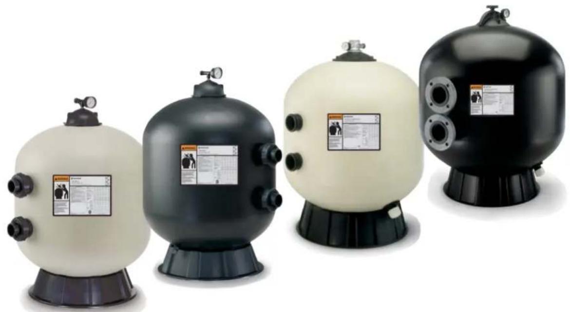
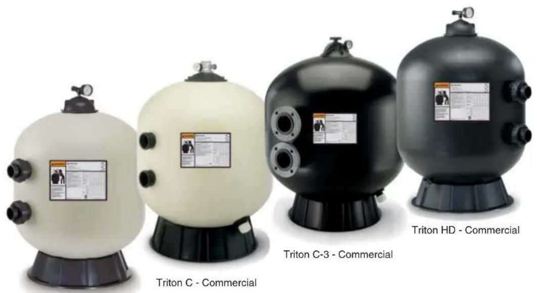
Triton® C and Triton® C-3 Commercial Sand Filters
This filter series features multiple diverters for increased filtration rates in commercial applications up to 20 GPM/Sq. Ft.
Triton® HD Side Mount Sand Filters
All the same great performance and features of the original Triton's with maximum operating pressure of 75 psi for those special high pressure installations such as single pump in-floor cleaning systems.
text_image
Triton C - Commercial Triton C-3 - Commercial Triton HD - CommercialTriton II - Residential
General Features
Triton ^® II
- Time-proven internal design ensures that all water receives maximum filtration for crystal clear results
- GlasLok™ process creates a one-piece, fiberglass reinforced tank with a UV-resistant coating for years of dependable, corrosion-resistant service
- Flow system design controls filtration quality and ensures maximum run times between backwashing to save you time
Triton ^® C and Triton ^® C-3
• Maximum Operating Pressure 50 psi
- Full 2 in. drain
- 8 in. opening for easy access to sand bed
- The Triton C-3 features standard 3 in. flange connections
• TR100C & TR140C models are available in black or almond
• TR100C-3 & TR140C-3 models are available in black only
Triton ^® HD
• Maximum Operating Pressure 75 psi
Additional Features:
- Combination sand and water drain speeds servicing and winterizing
- All internal parts are threaded for ease of maintenance
- Swing-away water diffuser allows instant access to sand and all internal parts
- NSF-Listed
NOTE: Before installing this product, read and follow all warning notices and instructions starting on page ii.
Installing the Triton® Fiberglass Sand Filter
Only a qualified service person should install the Triton Fiberglass Sand Filter. This filter is designed and intended for use to filter water.
Introduction
The following general information describes how to install the Triton Fiberglass Sand Filter. This filter operates under pressure and if assembled improperly or operated with air in the water circulation system, the top closure can separate and result in an accident causing property damage or serious bodily injury. A warning label has been affixed to the top of the filter and should not be removed. Keep safety labels in good condition and replace if missing or illegible.
How the Filter works
The high rate sand filter is designed to operate for years with a minimum of maintenance and when installed, operated and maintained in accordance with these instructions, it will provide years of trouble free operation.
Dirt is collected in the filter as the water flows through the control valve at the side of the filter and is directed into the top bulkhead. Dirty water flows into the diffuser at the top of the tank and is directed downward into the top surface of the filter sand bed. The dirt is collected in the sand bed and the clean water flows through the laterals and lower piping at the bottom of the filter up into the lower bulkhead. The flow then goes into the control valve at the side of the filter. Clean water is returned through the piping system into the pool.
The pressure will rise and the flow to the pool will be lowered as the dirt is collected in the filter. Eventually, the filter will become so plugged with dirt that it will be necessary to perform the backwash procedure. It is important to know when to backwash the filter. Backwashing is discussed further under the subsequent sections of this guide.
Please note that a filter removes suspended matter and does not sanitize the pool. The pool water must be sanitized and the water must be chemically balanced for sparkling clear water. Your filtration system should be designed to meet your local health codes. As a minimum, you must be sure that your system will turn over the total volume of water in your pool at least two to four times in a twenty-four hour period.
Refer to Table 1 for Filter Operation Data.
Table 1.
| FILTER MODELMODEL | FILTER AREA(Sq. Ft.) | Flow Rate*(GPM)@20 GPM/FT ^2 | Turnover Capacity (Gallons)(Based on 20 GPM / Sq. Ft.)* | |||
| 4 TURNS PER DAY 3 | TURNS PER DAY 2.4 | TURNS PER DAY 2 TURNS | TURNS PER DAY | |||
| TR40 1.92 38 | 13,680 18, | 240 22,800 27,360 | ||||
| TR50 2.46 49 | 17,640 23, | 520 29,400 35,280 | ||||
| TR60 3.14 63 | 22,680 30, | 240 37,800 45,360 | ||||
| TR60 ClearPro 3.1 | 4 63 22,680 | 30,240 37,800 45,360 | ||||
| TR100 | 4.91 74 | 26,640 35,520 44, | 400 53,280 | |||
| TR100HD | 4.91 74 | 26,640 35,520 44, | 400 53,280 | |||
| TR100C/TR100C-3 | 4.91 98 | 35,280 47,040 58, | 800 70,560 | |||
| TR140 | 7.06 | 106 38,160 | 50,880 63,600 76 | 320 | ||
| TR140C/TR140C-3 | 7.06 | 141 | 50,760 | 67,680 | 84,600 | 101,520 |
*TR100, TR100HD AND TR140 ARE BASED ON 15 GPM/SQ. FT.
WARNING
Failure to operate your filter system or inadequate filtration can cause poor water clarity obstructing visibility in your pool and can allow diving into or on top of obscured objects which can cause serious personal injury or drowning.
Clear water is the result of proper filtration as well as proper water chemistry. Pool chemistry is a specialized area and you should consult your local pool service specialist for specific details. In general, proper pool sanitation requires a free chlorine level of 1 to 3 PPM and a pH range of 7.2 to 7.6.
WARNING
Filters should never be tested or subjected to air or gas under pressure. All gases are compressible and under pressure create a danger. Severe bodily injury or property damage could occur if the filter is subjected to air or gas pressure.
- Check carton for any evidence of damage due to rough handling in shipment. If carton or any filter components are damaged, notify the freight carrier immediately.
- Carefully remove the accessory package and the filter tank from the carton.
- Mount the filter on a permanent slab, preferably concrete poured in a form or on a platform constructed of concrete block or brick. DO NOT use sand to level the filter or for the pump mounting, as it will wash away.
- Provide space and lighting for routine maintenance access. Do not mount electrical controls over the filter. One needs to be able to stand clear of the filter when starting the pump. Minimum space requirements may be found on the large nameplate on the filter.
- Position filter so that the port locations are in the desired final positions. Follow valve installation procedures.
- If you have a Multiport Valve, assemble the valve to the tank, being sure the o-ring on the valve fittings are in place and are clean. Use a lubricant, applied lightly, such as silicone grease, Dow #33, #40 or GE 300 or 623, or similar product on o-rings and o-ring grooves prior to assembly.
- If you have a two position slide valve, align the valve with the tank so that the handle is toward the top of the tank, push valve into ports and turn the valve nuts snugly on the tank fittings. It is not necessary to cinch the valve nuts to the tank fitting beyond hand tightness.
- The shipping straps used to support the TR100C-3, TR140C and the TR140C-3 multi-diffuser should be removed before loading sand and gravel in the filter.
- Sand specifications – be certain the proper sand is used as described in Table 2. Before pouring the sand into the filter, look inside and check the lower under-drain for broken or loose laterals (or fingers), which may have been accidentally damaged by rough handling during shipment. Replace any broken parts if necessary.
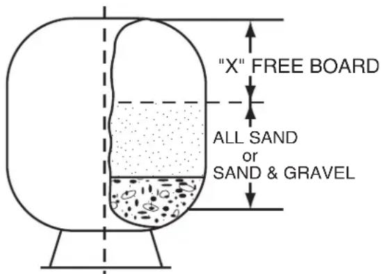
NOTE: The free board distance is the most important variable and should be maintained. Sand density will vary and therefore sand amount is given as a reference.
Table 2.
| MODEL | FREE BOARD“X” | ALL SAND*(POUNDS) | FILTER MEDIA†(POUNDS) | |
| PEA GRAVEL ‡ | SAND | |||
| TR40 8 1/4" | 175 50 125 | |||
| TR50 9 3/4" | 225 50 175 | |||
| TR60 10 1/2" | 325 50 275 | |||
| TR60 ClearPro 10 | 1/2" 325 50 275 | |||
| TR100 | 11 1/4" 600 | 150 | 450 | |
| TR100HD | 11 1/4" 600 | 150 | 450 | |
| TR100C-3 | 11 1/4" 600 | 150 | 450 | |
| TR140 | 13 1/2" 925 | 275 | 650 | |
| TR140C-3 | 13 1/2" 925 | 275 | 650 | |
text_image
"X" FREE BOARD ALL SAND or SAND & GRAVEL† Media required to meet NSF requirements.
‡ Pea Gravel to be 1/4" to 1/8" diameter.
* Sand to be No. 20 standard silica (uniformity coefficient not greater than 1.75) .018-.020 in diameter particle size.
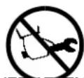
WARNING
Failure to position the Automatic Air Vent inside of the Closure will allow excessive trapped air to accumulate in the filter. Trapped air and the closure not properly closed can cause the closure to separate and could cause severe bodily injury and/or property damage.
- Pivot the diffuser out of the center of the tank on the TR40, 50, 60, TR60 ClearPro, 100 & 140 by rotating the diffuser assembly counter clockwise. (NOTE: The multi-diffuser assembly should not be moved on models TR100HD, TR100C, TR100C-3 and TR140C, TR140C-3. After installing the filter media as described below, check to make sure the tops on the diffusers are parallel to the top of the sand bed.) Fill the tank about half full of water. Pour pea gravel first (if used) and then the sand into the top of the filter at a slow rate so that the impact of the filter media does not damage the laterals. See Table 2 for the proper amounts of sand and gravel. Fill filter to the proper level to maintain freeboard, as shown in Table 2. Pivot the diffuser assembly back to its vertical position if it was moved. Be certain the automatic air vent is protruding into the top of the closure as indicated below in Figure 1. Ensure that the automatic air vent is in the center of the filter closure. Wash away all sand around the threaded opening at the top of the tank.
WARNING
For Threaded Closures
Use care when installing closure. The closure should turn freely in the filter, if resistance to closure

insertion is felt, then slowly remove the closure by turning counter-clockwise. The starting thread of the tank and closure must engage properly in order to secure the closure. Do not cross-thread closure.
The closure properly can cause the closure to separate and could cause severe bodily injury and/or property damage.
WARNING
For Oval Closures
Use care when installing closure. The closure should be inserted into the tank by placing the small

diameter of the oval closure into the larger diameter of the tank opening. Insert the side of the closure that does not have the pressure gauge and air bleeder first. The closure will need to be inserted at a 30° angle. Once the closure is inside the tank, it can be rotated 90° and lifted up to seal the tank. The aluminum bridge with load spring can then be placed over the closure bolt and the hand knob tightened to load the closure properly. The knob should be tightened by hand only. DO NOT USE A WRENCH TO TIGHTEN THE KNOB. You could damage the tank or closure and cause a failure by using a wrench. Failure to install the closure properly can cause the closure to separate and could cause severe bodily injury or property damage.
NEVER ATTEMPT TO TIGHTEN OR LOOSEN THE CLOSURE WITH THE PUMP RUNNING. Failure
to follow this instruction can result in the closure separating and causing severe bodily injury or property damage.
-
Assemble the pressure gauge and bleeder valve to the closure lid. Clean the lid o-ring and lubricate with silicone grease such as Dow #33, 40 or GE 300, 623 lubricant. Place the closure lid on the filter and tighten, making certain the air vent is up inside the dome of the closure.
-
With the plastic wrench, provided with the filter, tighten the closure as tight as possible using two hands on the wrench handles. As a minimum, the closure must be hand tight + 1/4 turn.
-
The oval closure that is used on the TR140C-3 and the TR100C-3 models will need to be installed as described in the above warning note for oval closures.
-
Assemble piping and pipe fittings to pump and valve. All piping must conform to local and state plumbing and sanitary needs.
-
Use sealant compounds on all male connections of pipe and fittings. Use only pipe compounds suited for plastic pipe. Support pipe to prevent strains on filter, pump or valve.
-
Long piping runs and elbows restrict flow. For best efficiency, use the fewest possible number of fittings, and large diameter pipe (at least 2" for TR100 and TR140, at least 3" for TR100C-3 and TR140C-3).
text_image
MANUAL AIR BLEEDER VALVE PRESSURE GAUGE CLOSURE AUTOMATIC AVI VENT TANKFigure 1.
CAUTION
Operating at excessive vacuum levels can cause the tank to crack and could cause property damage.
-
When installing backwash lines, it is recommended that a vacuum breaker be installed on installations where the backwash line length exceeds 40 ft. or the backwash line discharges more than 10 ft. lower than the surface of the pool. Alternately a vacuum break pit should be provided.
-
A check valve is recommended between the filter and heater to prevent hot water "back-up" which will damage the filter and valve.
-
The maximum operating pressure of the unit is 50 pounds per square inch (psi) and 75 pounds per square inch (psi) for the Triton HD model (only). Never operate this filter above these pressures or attach a pump to this filter that has more than 50 psi shut off pressure or 75 psi shut off pressure for the Triton HD model (only).
-
Never install a chlorinator upstream of the filter. Always locate downstream and with a check valve between the chlorinator and filter.
-
A positive shut off valve is not recommended at the outlet of the filtering system. If the system is ever run with such a valve closed, the internal air relief system becomes inoperative and risk of tank separation could exist. Additionally, running the system with no flow will seriously damage the equipment.
-
Never store pool chemicals within 10 ft. of your pool filter. Pool chemicals should always be stored in a cool, dry well ventilated area.
-
The oval closure used on the TR100C-3 and TR140C-3 is designed to provide a vacuum relief mechanism that protects the tank from vacuum conditions. The closure will allow air to enter the tank if the tank is higher than 8 ft. above the water level. In these cases, when the filter restarts after shut down, you may observe air being returned to the pool in the return fittings. This is not unusual, it is simply the automatic air relief in the filter removing the air in the filter.
Initial Start-up
-
On a new pool, clean the pool before filling the pool with water. Excessive dirt and large particles can cause damage to the pump and filter.
-
Ensure the backwash line is open so that water is free to come from the pool and flow out the backwash line. Set the valve position as follows:
a. If using a Multiport valve, set valve to backwash position.
b. If using a Two Position Slide Valve, push handle down to backwash position and engage lock by twisting handle.
- Check pump strainer pot to be sure it is full of water.
WARNING
Air entering a filter and tank closure not installed properly can cause the closure to separate and could cause severe bodily injury and/or property damage.
- Check closure on filter for tightness.
- Open the manual air bleeder on the filter closure. Stand clear of the filter and start the pump allowing it to prime.
- Close the air bleeder on the closure when all the air is removed from the filter and a steady stream of water emerges.
NOTE: Pool filter sand is typically pre-washed and should not require extensive backwashing. However, the shipping process may cause excessive abrasion which could require an extended backwash cycle at initial start-up; continue to backwash until the backwash water is as clear as the pool water.
CAUTION
To prevent equipment damage and possible injury, always turn the pump off before changing the valve position.
- Stop the pump. Set the valve position as follows:
a. If using a Multiport valve, set the valve to the filter position.
b. If using the Two Position Slide Valve, raise the handle to filter position and engage valve lock by twisting handle.
-
Ensure all suction and pool return lines are open so that water is free to come from the pool and return to the pool.
-
Open the manual air bleeder on the filter closure. Stand clear of the filter and start the pump.
- Close the air bleeder on the filter closure when all the air is removed from the filter and a steady stream of water emerges.
- The filter has now started its filtering cycle. You should ensure that water is returning to the pool and take note of the operating pressure when the filter is clean.
This section describes how to maintain your Triton ^® Fiberglass Sand Filter.
Filter Care
The filter is a very important part of the pool equipment and installation. Proper care and maintenance will add many years of service and enjoyment to the pool. Follow these suggestions for long trouble-free operations:
- To clean the exterior of the filter of dust and dirt, wash with a mild detergent and water then hose off. Do not use solvents.
- If internal maintenance is required, sand may be removed by removing the sand drain from the bottom of the filter and flushing with a garden hose. Pentair Water Pool and Spa, Inc. Sand Vacuum P/N 542090 may also be used.
- If after a number of years, the filter tank appears foggy in color or rough in texture, the tank surface can be painted. We recommend the use of a Quick Dry Spray Enamel. Do NOT paint the valve.

Always visually inspect filter components during normal servicing to ensure structural safety. Replace any item which is cracked, deformed or otherwise visually defective. Defective filter components can allow the filter top or attachments to separate and could cause severe bodily injury or property damage.
- The filter closure on your Triton Sand Filter was manufactured with high quality corrosion resistant materials. This part should be carefully inspected whenever servicing your filter. If excessive leakage is noted coming from the closure/tank interface, the closure and o-ring should be carefully inspected and replaced if any signs of deterioration exist.
- Your filter is a pressure vessel and should never be serviced while under pressure. Always relieve tank pressure and open air bleeder on the filter closure before attempting to service your filter.
- When restarting your filter, always open the manual air bleeder on the filter closure and stand clear of the filter.
Cleaning Frequency
- The filter on a new pool should be backwashed, and cleaned after approximately 48 hours of operation to clean out plaster dust and/or construction debris.
- There are three different ways to identify when the filter needs backwashing.
a. The most accurate indicator on pool systems with a flow meter is to backwash when the flow decreases 30% from the original (clean filter) flow. For example, if the original flow was 60 GPM, the filter should be backwashed when the flow is reduced by about 20 GPM (or 30%) to 40 GPM.
b. A more subjective and less accurate indicator is to observe the amount of water flowing from the flow directionals located in the wall of the pool. The filter should be backwashed once it is detected that the flow has been reduced by about 30%.
c. The most commonly used but less accurate indicator is to backwash when the filter gauge reading increases 10 PSI over the initial (clean filter) reading.
- It is important not to backwash the filter solely on a timed basis such as every three days. It is also important to note that backwashing too frequently actually causes poor filtration. Factors like weather conditions, heavy rains, dust or pollen, and water temperature all affect the frequency of backwash. As you use your pool, you will become aware of these influences.
- If at any time the starting pressure after backwashing the filter indicates 4 to 6 PSI higher than normal starting pressure, it is time to perform a chemical cleaning procedure.
Filter Backwash Procedure
WARNING
To prevent equipment damage and possible injury, always turn off pump before changing valve positions.
- Stop the pump.
- Ensure that the suction and backwash lines are open so that water is free to come from the pool and flow out the backwash line. Set control valve position as follows:
a. If using a Multiport Valve, set valve to backwash position.
b. If using a Two Position Slide Valve, push handle down to backwash position and engage lock by twisting handle.
-
Stand clear of the filter and start pump.
-
Backwash filter for approximately 3 to 5 minutes or until backwash water is clean.
-
Stop the pump.
a. If using a Multiport Valve, set valve to rinse position and continue with remaining steps.
b. If using a Two Position Slide Valve, skip to step 8.
-
Stand clear of the filter and start pump.
-
Rinse filter for approximately 30 seconds.
-
Stop the pump and set valve as follows:
a. If using a Multiport Valve, set valve to filter position.
b. If using a Two Position Slide Valve, raise handle to filter position and engage valve lock by twisting handle.
-
Ensure that pool return line is open so that water may freely flow from the pool back to the pool.
-
Open manual air bleeder on Triton closure. Stand clear of filter and start pump.
-
Close manual air bleeder of the closure when all the air is removed and a steady stream of water emerges from the bleeder.
-
The filter has now started its filtering cycle. You should ensure that water is returning to the pool and take note of the filter pressure.
-
The filter pressure, in the above Step 12, should not exceed the pressure originally observed on the filter when it was initially started. If after backwashing, the pressure is 4 to 6 PSI above the start condition, it will be necessary to chemically clean the sand bed.
Chemical Cleaning Procedure
- It is recommended that an approved cleaner be used. Please contact your local pool chemical supplier or retail store for the proper cleaner.
These cleaners will remove oils, scale and rust from the sand bed in one cleaning operation. - Mix a solution following the manufacturers instructions on the label.
- Backwash the filter as outlined on page 8.
- If the filter is below pool level, shut off the pump and close appropriate valving to prevent draining the pool.
- Shut off pump, open filter drain and let filter drain. Place valve in backwash position.
- After filter has drained, close filter drain and remove the pump strainer pot lid.
- Ensure that the backwash lines are open.
- Turn the pump on and slowly pour the cleaning solution into the pump strainer with the pump running.
- Continue adding solution until the sand bed is saturated with cleaning solution. Replace lid on pump.
- Shut off the pump and leave filter in backwash position. Allow filter to stand overnight (12 hours).
- Replace the pump lid and follow backwash procedures on page 8.
- Do not allow the cleaning solution to get into the pool.
Winterizing your Filter
- In areas that have freezing winter temperatures, protect the pool equipment by backwashing the filter.
- After backwashing, shut the pump off, open the manual air bleeder on the closure and adjust the valve as follow:
a. On the Multiport Valves, move the handle of the valve to the Winterize Position (*).
b. On the Two Position Slide Valve, if possible, remove the valve piston assembly; clean, lubricate and store in a dry location for the winter.
*NOTE: The Multiport valve should be left in the winterize position during shutdown season so the valve diverter has no pressure on the rubber seal.
-
On the TR40, 50, 60, and TR60 ClearPro, remove the wing-type plug on the bottom of the filter. On the TR100, TR100HD, TR100C, TR100C-3, and TR140, TR140C, TR140C-3, remove the 1 12 " drain plug cap. The filter will drain very slowly, and therefore, it is recommended that the drain plug be left out.
-
Drain all appropriate system piping.
-
We recommend covering the equipment with a tarpaulin or plastic sheet to inhibit deterioration from weather. Do NOT wrap pump motor with plastic.
Section 4
Troubleshooting
Use the following troubleshooting information to resolve possible problems with your Triton® Filter.

THIS FILTER OPERATES UNDER HIGH PRESSURE

When any part of the circulating system, (e.g., closure, pump, filter, valve(s), etc.), is serviced, air can enter the system and become pressurized. Pressurized air can cause the top closure to separate which can result in severe injury, death, or property damage. To avoid this potential hazard, follow these instructions:
- If you are not familiar with your pool filtering system and/or heater:
a. Do NOT attempt to adjust or service without consulting your dealer, or a qualified pool technician.
b. Read the entire Installation & User's Guide before attempting to use, service or adjust the pool filtering system or heater.
- Before repositioning valve(s) and before beginning the assembly, disassembly, or any other
service of the circulating system: (A) Turn the pump OFF and shut OFF any automatic controls to ensure the system is NOT inadvertently started during the servicing; (B) open the manual air bleeder valve; (C) wait until all pressure is relieved.
- Whenever installing the filter closure FOLLOW THE FILTER CLOSURE WARNINGS EXACTLY.
-
Once service on the circulating system is complete FOLLOW INITIAL START-UP INSTRUCTIONS EXACTLY.
-
Maintain circulation system properly. Replace worn or damaged parts immediately, (e.g., closure, pressure gauge, valve(s), o-rings, etc).
-
Be sure that the filter is properly mounted and positioned according to instructions provided.
NOTE: Turn off power to unit prior to attempting service or repair.
Problems and Corrective Actions
| PROBLEM | CAUSE | REMEDY |
| Pool water not sufficiently clean | 1. Pool chemistry not adequate to inhibit algae growth.2. Too frequent a backwash cycle.3. Improper amount or wrong sand size.4. Inadequate turnover rate. | Maintain pool chemistry or consult pool service technician.Allow pressure to build to 10 psi above clean filter condition before backwashing.Check sand bed Freeboard and sand size or consult a pool service technician.Run system for longer time or consult dealer or pool service technician. |
| High filter pressure | 1. Insufficient backwashing.2. Sand bed plugged with mineral deposits.3. Partially closed valve. | Backwash until effluent runs clear.Chemically clean filter.Open valve or remove obstruction in return line. |
| Short cycles | 1. Improper backwash.2. Pool chemistry not adequate to inhibit algae growth.3. Plugged sand bed.4. Flow rate too high. | Backwash until effluent runs clear.Maintain pool chemistry or consult pool service technician.Manually remove top 1" surface of sand bed, replace with new sand and chemically clean entire sand bed as described in the Chemical Cleaning Procedure.Restrict flow to capacity of filter. |
| Return flow to pool diminished,low filter pressure lint strainer.2. Obstruction in pump. Disassemble and clean pump.3. Obstruction in suction line to pump. Clean skimmer basket. Remove obstruction in lines.Open valves in suction line. | 1. Obstruction in pump hair and clean pump. | Clean basket in pump strainer. |
| Sand returning to pool 1. Broken under drain lateral. Replace broken or damaged laterals. | ||
| Sand loss to waste2. Improper sand size.3. Air strainer is damaged or missing. | 1. Backwash rate too high.Change to proper sand.Replace damage components. | Reduce backwash flow rate. |
| Leak at closureopen air bleeder, tighten closure properly.2. Dirt or contamination on sealing surface.Shut off pump, relieve tank pressure, open air bleeder, remove closure and clean all sealing surfaces. Reassemble closure properly.3. Damaged part.closure, tank or any combination of parts as required. | 1. Improperly tightened closure. | Shut off pump, relieve tank pressure,Same as above except replace damaged o-ring, |
| Leak at bulkheadremove closure and remove sand to access leakingthe special wrench, P/N 154020, hold the 3" flange3" flange adapter. Hand tighten plus 1/2 turn.2. Dirt or contamination on sealing surfaces.Shut off pump, relieve tank pressure, open air bleeder, remove closure and remove sand to access leaking bulkhead. Remove attached tank internals and remove bulkhead assembly. Clean all mating surfaces and seals. Replace the bulkhead assembly, being careful to assemble properly.Tigthen assembly as indicated above.combination of parts.3. Damaged part. | 1. Improper tightened bulkhead assembly. | Shut off pump, relieve tank pressure, open air bleeder,bulkhead on TR40, 50, 60, TR60 ClearPro, 100, 100C, 140 or 140C. Hold the 2" bulkhead and tighten the 2" internal locknut. On the TR100C-3/TR140C-3, using spacer and with wrench, P/N 154019, tighten theSame as above except replace damaged part or |
Section 5
Replacement Parts
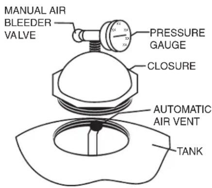
Pressure Drop Curve for the Triton® Series Fiberglass Sand Filters
line
| Índice de Flujo (GPM) | TR40 | TR50 | TR60 | | --------------------- | ---- | ---- | ---- | | 0 | 0 | 0 | 0 | | 20 | 1 | 1 | 1 | | 40 | 2 | 2 | 2 | | 60 | 3 | 3 | 3 | | 80 | 4 | 4 | 4 | | 100 | 5 | 5 | 5 | | 120 | 6 | 6 | 6 | | 140 | 7 | 7 | 7 | | 160 | 8 | 8 | 8 | | 180 | 9 | 9 | 9 | | 200 | 10 | 10 | 10 | | 220 | 11 | 11 | 11 | | 240 | 12 | 12 | 12 | | 260 | 13 | 13 | 13 | | 280 | 14 | 14 | 14 | | 300 | 15 | 15 | 15 | | 320 | 16 | 16 | 16 | | 340 | 17 | 17 | 17 | | 360 | 18 | 18 | 18 | | 380 | 19 | 19 | 19 | | 400 | 20 | 20 | 20 | | 420 | 21 | 21 | 21 | | 440 | 22 | 22 | 22 | | 460 | 23 | 23 | 23 | | 480 | 24 | 24 | 24 | | 500 | 25 | 25 | 25 | | 520 | 26 | 26 | 26 | | 540 | 27 | 27 | 27 | | 560 | 28 | 28 | 28 | | 580 | 29 | 29 | 29 | | 600 | 30 | 30 | 30 | | 620 | 31 | 31 | 31 | | 640 | 32 | 32 | 32 | | 660 | 33 | 33 | 33 | | 680 | 34 | 34 | 34 | | 700 | 35 | 35 | 35 | | 720 | 36 | 36 | 36 | | 740 | 37 | 37 | 37 | | 760 | 38 | 38 | 38 | | 780 | 39 | 39 | 39 | | 800 | 40 | 40 | 40 | | 820 | | | | | 840 | | | | | 860 | | | | | 880 | | | | | 900 | | | | | 920 | | | | | 940 | | | | | 960 | | | | | 980 | | | | | | | | | | | | | | | | | | | | | | | | | | | | | | | | | | | | | | | | | | | | | | | | | | | | | | | | | | | | | | | | | - (Tr40) | | - (TR50) | | - (TR60) | The data is already in CSV format: The original table contains the original table data for TR40, TR50, and TR60. The data is presented in a tabular format as follows: Table data for each variable. The table data is presented in the same order as the original table data. There are two additional columns in the table data: 'TR40' and 'TR50' for the first column of the table data; 'TR60' and 'TR5' for the second column of the table data. The table data is presented in the same order as it was provided in the code.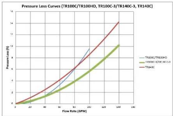
line
| Flow Rate (GPM) | TR100C/TR100HD | TR100C-3/TR140C-3 | TR140C | | --------------- | -------------- | ----------------- | ------ | | 0 | 6 | 6 | 6 | | 20 | 8 | 7 | 9 | | 40 | 12 | 10 | 15 | | 60 | 20 | 15 | 25 | | 80 | 35 | 25 | 40 | | 100 | 60 | 45 | 65 | | 120 | 85 | 75 | 95 | | 140 | 110 | 105 | 125 | | 160 | 135 | 125 | 155 |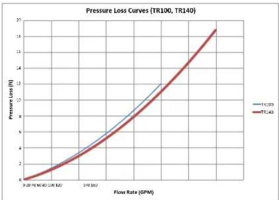
line
| Flow Rate (GPM) | Pressure Loss (ft) TR100 | Pressure Loss (ft) TR140 | | --------------- | ------------------------ | ------------------------ | | 0 | 0 | 0 | | 10 | 2 | 2 | | 20 | 4 | 4 | | 30 | 6 | 6 | | 40 | 8 | 8 | | 50 | 10 | 10 | | 60 | 12 | 12 | | 70 | 14 | 14 | | 80 | 16 | 16 | | 90 | 18 | 18 | | 100 | 20 | 20 |Installing Multiple Filters with Tandem Filter Piping Kits
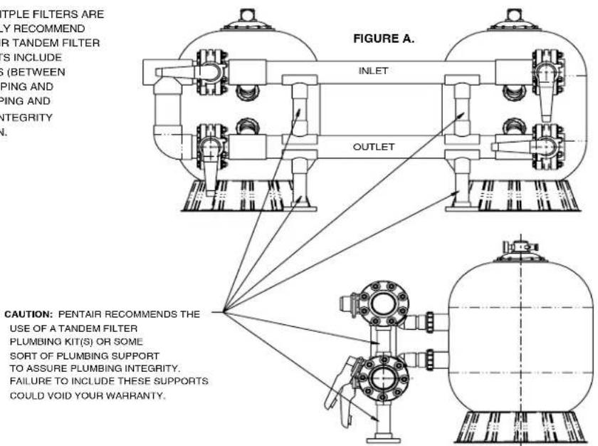
CAUTION: WHEN MULITPLE FILTERS ARE
INSTALLED, WE HIGHLY RECOMMEND
THE USE OF A PENTAIR TANDEM FILTER
PIPING KIT. THESE KITS INCLUDE
PLUMBING SUPPORTS (BETWEEN
INLET AND OUTLET PIPING AND
BETWEEN OUTLET PIPING AND
FLOOR) TO ASSURE INTEGRITY
OF THE INSTALLATION.
SEE FIGURE A.
text_image
APPLE FILTERS ARE VERY RECOMMEND OR TANDEM FILTER S INCLUDE G (BETWEEN PING AND PING AND INTEGRITY A. FIGURE A. INLET OUTLET CAUTION: PENTAIR RECOMMENDS THE USE OF A TANDEM FILTER PLUMBING KIT(S) OR SOME SORT OF PLUMBING SUPPORT TO ASSURE PLUMBING INTEGRITY. FAILURE TO INCLUDE THESE SUPPORTS COULD VOID YOUR WARRANTY.TRITON® II & TR60 CLEARPRO FIBERGLASS SAND FILTER
Replacement Parts
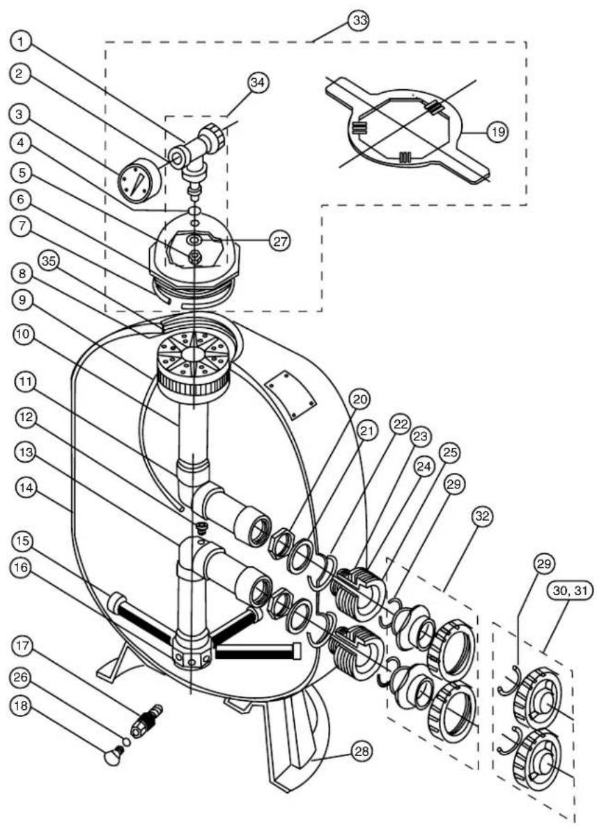
text_image
Technical diagram of a mechanical device with numbered components and exploded view, likely for assembly or maintenance instructions.TR40
TR50
TR60
TR60 ClearPro
TR100
TR140
text_image
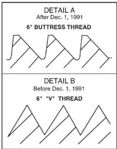
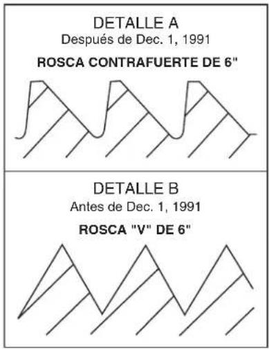
DETAIL A After Dec. 1, 1991 6" BUTTRESS THREAD DETAIL B Before Dec. 1, 1991 6" "V" THREADFilters manufactured after Dec 1, 1991 utilize a 6 in. buttress thread in the filter tank top opening and on the closure, see Detail A.
Filters manufactured before Dec 1, 1991 utilize a 6 in. "V" type thread, see Detail B.
6 in. closures in Detail A. and B. are NOT Interchangeable.
text_image
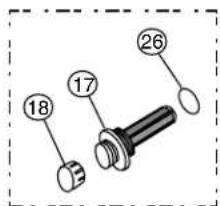
17 18 26★ Used on
TR100 and
TR140 filters.
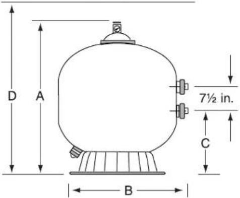
Vertical Clearance Required
text_image
D A 7½ in. C B| MODEL A D | DIM. B DIM. | C DIM. D | DIM. | |
| TR40 30 12 | in. 19 12 in. | 10 34 in. | 32 12 in. | |
| TR50 34 34 | in. 21 12 in. | 11-7/8 in. | 36 34 in. | |
| TR60 35 12 | in. 24 12 in. | 13-5/8 in. | 37 12 in. | |
| TR60 ClearPro 3 | 5 12 in. 24 12 | in. 13-5/8 | in. 37 12 in. | |
| TR100 39 34 | in. 30 12 in. | 16 14 in. | 41 34 in. | |
| TR140 45 14 | in. 36 12 in. | 18 34 in. | 47 14 in. |
| Item No. | Part No. | TRITON II & TR60 CLEARPRO SAND FILTERS Description |
| 1 154 | 689 Air bleeder/tee assy. | |
| 2 154 | 700 Adapter - brass air bleeder | |
| 3 155 | 050 Gauge - back mount pressure | |
| 4 154 | 661 O-ring - air bleeder adapter | |
| 5 154 | 664 Nut - 3/8 in. - 16 s/s | |
| 6 154 | 570 Closure - 6 in. buttress thread, see Detail A | |
| 6 154 | 559 Closure - 6 in. “V” thread Blk., see Detail B | |
| 7 154 | 493 O-ring closure, white | |
| 8 150 | 035 Strainer ECL/TR | |
| 9 150 | 039 Tube air relief TR40 | |
| 9 150 | 040 Tube air relief TR50/60 | |
| 9 150 | 041 Tube air relief TR100 | |
| 9 150 | 042 Tube air relief TR140 | |
| 10 154 | 598 Diffuser assy. TR40/50 | |
| 10 154 | 599 Diffuser assy. TR60 | |
| 10 154 | 462 Diffuser assy. TR100 | |
| 10 154 | 4906 Diffuser assy. TR140 | |
| 11 154 | 803 Piping assy. upper TR40 | |
| 11 154 | 814 Piping assy. upper TR50 | |
| 11 154 | 533 Piping assy. upper TR60 | |
| 11 154 | 426 Piping assy. upper TR100 | |
| 11 154 | 500 Piping assy. upper TR140 | |
| 12 150 | 036 Connector air relief tube | |
| 13 154 | 801 Piping assy. lower TR40 | |
| 13 154 | 6816 Piping assy. lower TR50 | |
| 13 154 | 805 Piping assy. lower TR60 | |
| 13 154 | 5284 Piping assy. lower TR60 ClearPro -1/4 Turn Lateral | |
| 13 154 | 807 Piping assy. lower TR100 | |
| 13 154 | 489 Piping assy. lower TR140 | |
| 14 154 | 636 Tank & ft. assy. TR40 - 6 in. btr. thd., Detail A | |
| 14 154 | 637 Tank & ft. assy. TR50 - 6 in. btr. thd., Detail A | |
| 14 154 | 638 Tank & ft. assy. TR60 - 6 in. btr. thd., Detail A | |
| 14 154 | 639 Tank & ft. assy. TR100 - 6 in. btr. thd., Detail A | |
| 14 154 | 640 Tank & ft. assy. TR140 - 6 in. btr. thd., Detail A |
TRITON® II and TR60 CLEARPRO FIBERGLASS SAND FILTER
Replacement Parts
TR40
TR50
TR60
TR60 ClearPro
TR100
TR140
NOTES
Filters manufactured after Dec 1, 1991 utilize a 6 in. buttress thread in the filter tank top opening and on the closure, see Detail A.
Filters manufactured before Dec 1, 1991 utilize a 6 in. "V" type thread, see Detail B.
6 in. closures in Detail A. and B. are NOT interchangeable.
To determine manufacture date, the first 4 digits of the serial number indicate the month and year product was manufactured.
TR60 ClearPro - 1/4 Turn Lateral for filters manufactured after May 15, 2007 utilize Lower Piping Assy. P/N 155284.
text_image
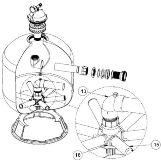
Technical diagram of a mechanical device with numbered parts, showing internal components and assembly steps.DETAILED VIEW
Detail for Triton® II - TR60 Filters with ClearPro Technology®
| Item No. | Part No. | TRITON II & TR60 CLEARPRO SAND FILTERS Description |
| 15 152 | 290 Lateral - 6 | 11/16 in. L TR40/50/60, 8 req. |
| 15 150 | 085 Lateral Assy. - 1/4 turn TR60, 6 req. | |
| 15 150 | 088 Lateral Assy. - TR60 ClearPro, 6 req. | |
| 15 152 | 202 | Lateral - 9 1/8 in. L TR100, 8 req. 2 |
| 15 154 | 543 | Lateral - 612 in. L TR100, 8 req. 1 |
| 15 154 | 540 Lateral - 12 | in. L TR140, 8 req. |
| 16 154 | 763 Hub Lateral TR40/50/60 | |
| 16 152 | 222 Hub Assy TR60 ClearPro | |
| 16 154 | 453 Hub Lateral TR100/140 | |
| 17 152 | 220 | Sand drain 2 in. 6 |
| 17 154 | 698 | Spigot 34 in. NPT sand drain 4 |
| 17 154 | 685 | Spigot 12 in. NPT sand drain 3 |
| 18 154 | 871 | Cap thd. 112 in. 6 |
| 18 357 | 161 Plug 14 in. NPT drain | |
| 19 154 | 512 Wrench 6 in. closure | |
| 19 154 | 510 Wrench closure aluminum | |
| 19 151 | 608 Wrench 812 in. closure aluminum | |
| 20 154 | 412 Locknut 2 in. internal, 2 req. | |
| 21 154 | 416 Spacer 2 n. internal, 2 req. | |
| 22 154 | 492 O-ring 2 in. bulkhead, 2 req. | |
| 23 154 | 408 Spacer 2 n. external, 2 req. | |
| 24 154 | 538 Gasket 2 n. bulkhead, 2 req. | |
| 25 154 | 405 Bulkhead 2 in., 2 req. | |
| 26 274 | 494 | O-ring 3/16 in. X 2 5/8 in. i.d. 6 |
| 26 192 | 115 O-ring #2-12 air adapter | |
| 27 154 | 418 Washer 3/8 in. s/s | |
| 28 154 | 926 Foot 16 in. dia., TR40/50 (see NOTE 1) | |
| 28 154 | 520 Foot 19 in. dia., TR60 (see NOTE 1) | |
| 28 154 | 596 Foot 24 in. dia., TR100/140 (see NOTE 1) | |
| 29 274 | 494 O-ring valve adptr., 2 req. | |
| 30 271 | 092 | 2 in. thd. adptr. kit 5 |
| 31 271 | 094 | 112 in. thd. adptr. kit 5 |
| 32 271 | 096 | 112 in. & 2 in. slip adptr. kit 5 |
| 33 154 | 641 Kit closure, 6 in. buttress thd., Blk., DETAIL A | |
| 33 154 | 697 Kit closure, 6 in. “V” thd., Tan, DETAIL B | |
| 33 154 | 856 Kit closure, 812 in. buttress thd., Blk. | |
| 34 154 | 687 Fitting package complete (see NOTE 2) | |
| 35 154 | 611 Spacer air vent strainer 334 in. TR40 | |
| 35 154 | 612 Spacer air vent strainer 412 in. TR50/60 | |
| 35 154 | 613 Spacer air vent strainer 512 in. TR100 | |
| 35 154 | 614 Spacer air vent strainer 5 in. TR140 | |
| 154402 Tape ft. mounting TR40/50/60, 3 req. | ||
| 154407 Tape ft. mounting TR100/140, 3 req. | ||
| 151602 Bulkhead wrench 2 in. | ||
| 154714 Bulkhead kit, include items 20-25 |
TRITON® II and TR60 CLEARPRO FIBERGLASS SAND FILTER
Replacement Parts
TR40
TR50
TR60
TR60 ClearPro
TR100
TR140
NOTES
Filters manufactured after Dec 1, 1991 utilize a 6 in. buttress thread in the filter tank top opening and on the closure, see Detail A.
Filters manufactured before Dec 1, 1991 utilize a 6 in. "V" type thread, see Detail B.
6 in. closures in Detail A. and B. are NOT interchangeable.
To determine manufacture date, the first 4 digits of the serial number indicate the month and year product was manufactured.
① Used on Filters manufactured before 5-85.
② Used on Filters manufactured after 5-85.
③ Used on Filters manufactured before 3-83.
④ Used on Filters manufactured after 3-83 thru 3-96.
⑤ For Installations w/out Valve (Pair).
⑥ Used on TR100 & 140 Filters.
NOTE 1: Replacement of tank foot requires the use of foot mounting tape. See P/N's.
NOTE 2: Fitting package includes items 1, 2, 4, 5 and 27.
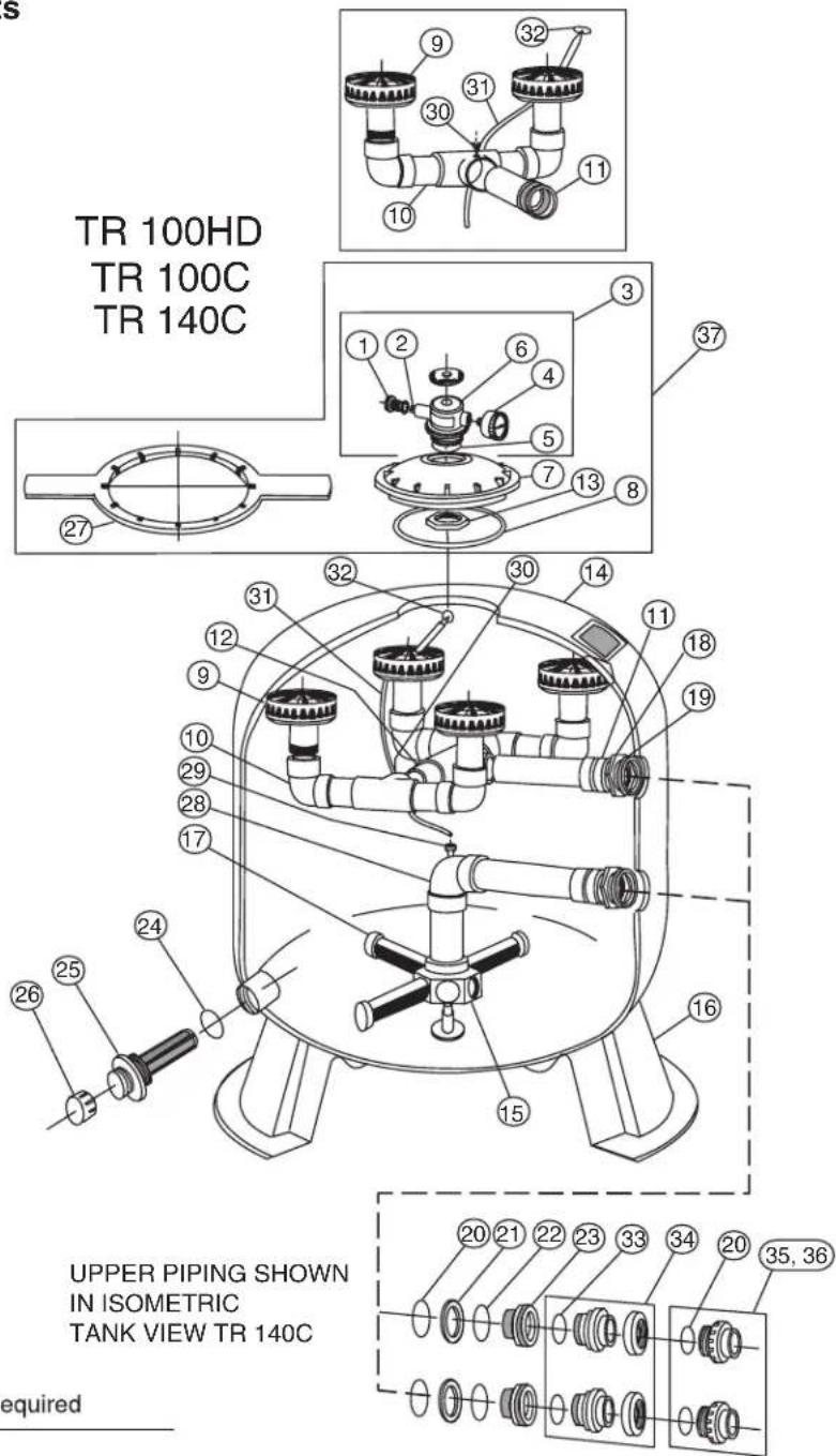
TRITON® 100HD, 100C & 140C FIBERGLASS SAND FILTER
Replacement Parts
TR100HD
TR100C
TR140C
text_image
TR 100HD TR 100C TR 140C UPPER PIPING SHOWN IN ISOMETRIC TANK VIEW TR 140C required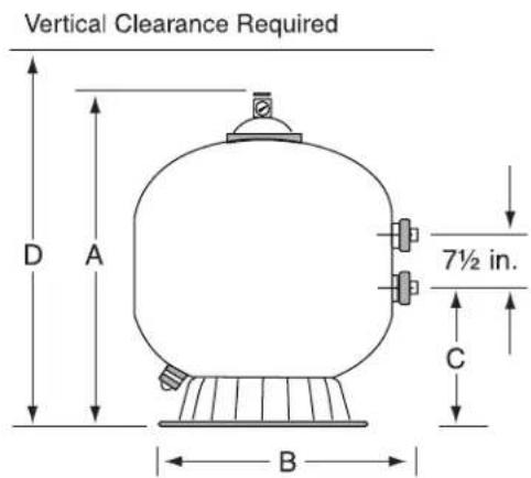
text_image
Vertical Clearance Required D A 7½ in. C B| MODEL | A DIM. | B DIM. | C DIM. | D DIM. |
| TR100HD | 39 34 in. | 30 12 in. | 16 14 in. | 41 34 in. |
| TR100C | 39 34 in. | 30 12 in. | 16 12 in. | 43 34 in. |
| TR140C | 45 14 in. | 36 12 in. | 18 34 in. | 49 14 in. |
| Item No. | Part No. | TR100HD, TR100C & TR140C SAND FILTERS Description |
| 1 27 | 3512 Air bleeder w/ o-ring | |
| 2 27 | 3513 O-ring air bleeder screw | |
| 3 27 | 3564 Manual air relief body assy. | |
| 4 15 | 5050 Pressure Gauge | |
| 4 99 | 1481 Pressure Gauge TR100C/TR100HD 2 | |
| 5 27 | 4494 O-ring 3/16 in. X 2-5/8 in. i.d.. | |
| 6 27 | 3564 Valve body machined | |
| 7 15 | 4575 Closure 812 in. buttress | |
| 8 15 | 2509 Square ring 812 in. | |
| 9 15 | 4599 Diffuser TR100C/TR100HD 1 | |
| 9 15 | 4599 Diffuser TR140C 1 | |
| 10 15 | 6355 | Piping assy. upper TR100C/TR100HD/TR140C 1 |
| 11 15 | 6344 | Piping assy. upper inlet TR100C/TR100HD/TR140C |
| 12 15 | 6354 Piping connecting assy. upper TR140C | |
| 13 15 | 4412 Nut 2 in. internal | |
| 14 15 | 3430 | Tank & ft. assy. TR100C/TR100HD - 812 in. btr. THD. - Blk |
| 14 15 | 3431 Tank & ft. assy. TR140C - 812 in. btr. THD. - Blk | |
| 14 15 | 6224 Tank & ft. assy. TR100HD - btr. thd. - Blk 2 | |
| 15 15 | 4453 Hub lateral TR100C/TR100HD/TR140C | |
| 16 15 | 4596 Foot 24 in. dia. TR100C/TR100HD/TR140C | |
| 17 15 | 2202 Lateral 9 1/8 in. TR100C/TR100HD, 8 req. | |
| 17 15 | 4540 Lateral 12 in. TR140C, 8 req. | |
| 18 15 | 4412 Locknut 2 in. internal | |
| 19 15 | 4416 Spacer 2 in. internal | |
| 20 15 | 4492 O-ring 2 in. bulkhead | |
| 21 15 | 4408 Spacer 2 in. external | |
| 22 15 | 4538 Gasket 2 in. bulkhead | |
| 23 15 | 4405 Bulkhead 2 in. | |
| 24 27 | 4494 O-ring 3/16 in. X 2 5/8 in. i.d. | |
| 154407 Tape ft. mounting | ||
| 25 15 | 2220 2 in. sand drain | |
| 26 15 | 4871 Cap thd. 112 in. | |
| 27 15 | 4527 Wrench 812 in. closure | |
| 27 15 | 1608 Wrench 812 in. aluminum | |
| 28 15 | 4807 Piping assy. lower TR100C/TR100HD | |
| 28 15 | 4489 Piping assy. lower TR140C | |
| 29 15 | 0036 Connector air relief tube |
TRITON® 100HD, 100C & 140C FIBERGLASS SAND FILTER
Replacement Parts
TR100HD
TR100C
TR140C
| Item No. | Part No. | TR100HD, TR100C & TR140CSAND FILTERSDescription |
| 30 27 | 3071 Screw #14 18-8 TR100C/TR100HD 1 | |
| 31 15 | 0041 Tube air relief TR100C/TR100HD | |
| 31 15 | 0042 Tube air relief TR140C | |
| 32 15 | 0035 Strainer air relief | |
| 33 27 | 4494 O-ring valve adptr. | |
| 34 27 | 1096 | 112 in. & 2 in. slip adptr. kit for inst. w/o valve (pair) |
| 35 27 | 1092 2 in | thd. adptr. kit for inst. w/o valve (pair) |
| 36 27 | 1094 112 | in. thd. adptr. kit for inst. w/o valve (pair) |
| 37 15 | 4856 Kit closure 812 in. btr. THD. - Blk. | |
| 37 15 | 5738 Kit closure 812 2 |
NOTES
① Different quantities required for TR100C and TR140C Filters.
② Used on TR1000HD Filters
TRITON® 100C-3 & 140C-3 FIBERGLASS SAND FILTER
Replacement Parts
TR100C-3
TR140C-3
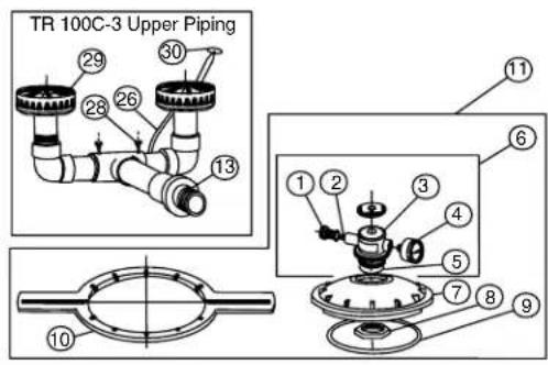
text_image
TR 100C-3 Upper Piping ① ② ③ ④ ⑤ ⑥ ⑦ ⑧ ⑨ ⑩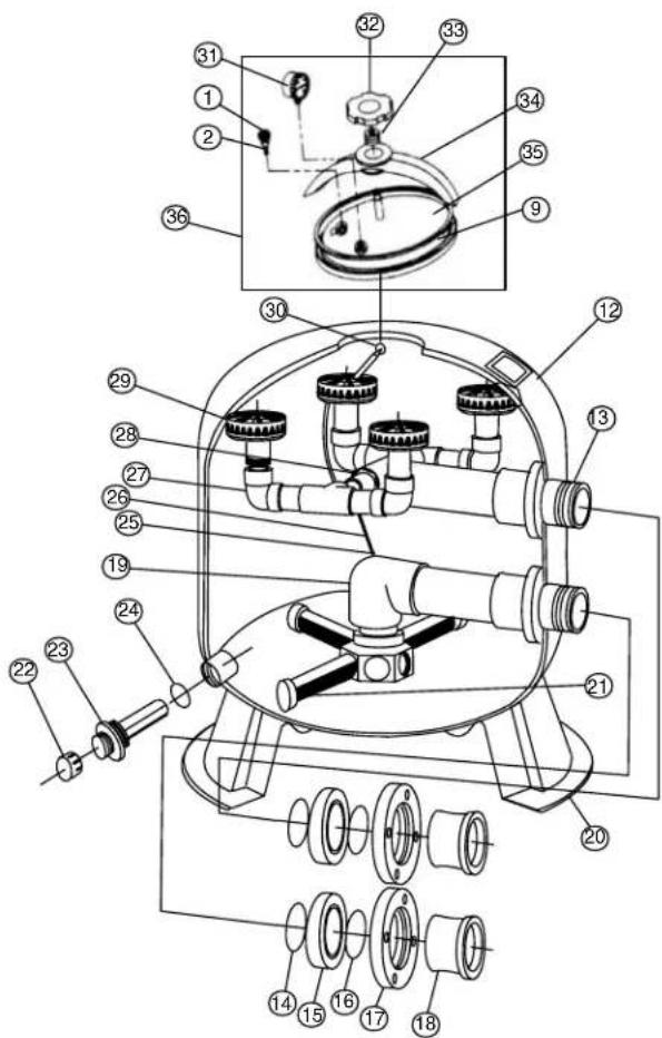
text_image
Technical diagram of a mechanical surveying instrument with numbered parts for identificationVertical Clearance Required
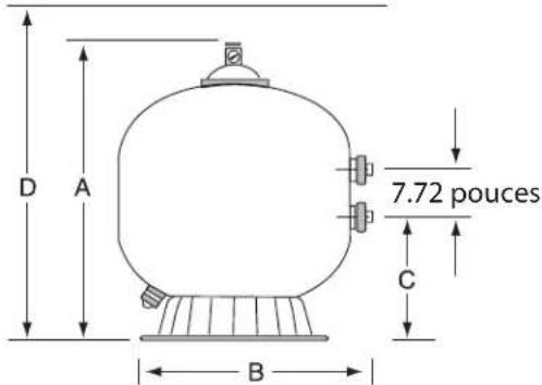
text_image
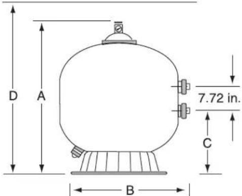
D A 7.72 in. C B| MODEL A | DIM. B DIM. C DIM. D DIM. | |
| TR100C-3 3 | 934 in. 3012 in. 16-1/1 | 6 in. 4334 in. |
| TR140C-3 4 | 514 in. 3612 in. 1812 in. | 4914 in. |
| Item No. | Part No. | TRITON 100C-3 &140C-3 SAND FILTERS Description |
| 1 27 | 3512 Air bleed with o-ring 23 | |
| 2 27 | 3513 O-ring air bleeder screw 2 | |
| 3 27 | 3564 Valve body machined 2 | |
| 4 15 | 5050 Pressure gauge 2 | |
| 5 15 | 4494 O-ring adapter, 6 in. 2 | |
| 6 27 | 3564 Manual air relief assy. 2 | |
| 7 15 | 4575 Closure 812 in. 2 | |
| 8 15 | 4412 Nut 2 in. internal 2 | |
| 9 15 | 2509 Square ring closure 23 | |
| 10 15 | 4527 Wrench 812 in. closure 2 | |
| 11 15 | 4856 Kit 812 in. closure buttress thd. 2 | |
| 11 15 | 6842 Kit 812 in. closure w/gasket 4 | |
| 12 15 | 3430 Tank & ft. assy. TR100C-3 - buttress | |
| 12 15 | 3431 Tank & ft. assy. TR140C-3 - buttress | |
| 13 15 | 4007 Upper piping assy. TR100C-3 | |
| 13 15 | 4008 Upper piping assy. TR140C-3 | |
| 14 15 | 4005 O-ring Parker 2-343, 2 req. | |
| 15 15 | 4002 Spacer 3 in., 2 req. | |
| 16 15 | 4004 O-ring Parker 2-342, 2 req. | |
| 17 15 | 4003 Flange 3 in., 2 req. | |
| 18 15 | 4001 Adapter flange 3 in., 2 req. | |
| 19 15 | 4009 Lower piping assy. TR100C-3 | |
| 19 15 | 4010 Lower piping assy. TR140C-3 | |
| 20 15 | 4596 Foot 24 dia. TR100C-3/140C-3 | |
| 21 15 | 2202 Lateral 9 in. TR100C-3, 8 req. | |
| 21 15 | 4540 Lateral 12 in. TR140C-3, 8 req. | |
| 22 15 | 4871 Cap thd. 112 in. | |
| 23 15 | 2220 Sand drain 2 in. | |
| 24 27 | 4494 O-ring 3/16 in. X 2 5/8 in. i.d., 2 req. | |
| 25 15 | 4441 Connector air relief tube | |
| 26 15 | 0041 Tube air relief TR100C-3 (23 in.) | |
| 26 15 | 0042 Tube air relief TR140C-3 (27 in.) | |
| 27 15 | 4018 Diffuser piping assy. TR140C-3, 2 req. | |
| 28 55 | 2474 Screw - #10- 112 in. flathead phillips, 2 req. | |
| 29 15 | 4599 Diffuser - 2 req'd. for TR100C-3 | |
| 29 15 | 4599 Diffuser - 4 req'd. for TR140C-3 |
TRITON® 100C-3 & 140C-3 FIBERGLASS SAND FILTER
Replacement Parts
TR100C-3
TR140C-3
| Item No. | Part No. | TRITON 100C-3 &140C-3 SAND FILTERS Description |
| 30 15 | 0035 Strainer ELC/TR | |
| 31 19 | 0058 Pressure Gauge, 14 in. psi 3 | |
| 32 15 | 4581 Knob TR oval 3 | |
| 33 15 | 4582 Spring TR oval 3 | |
| 34 15 | 4579 Bridge TR oval 3 | |
| 35 15 | 4576 Closure-oval 3 | |
| 36 15 | 6841 Kit TR oval closure 1 3 |
NOTES
① P/N 156841 includes items: 1, 9, 31 thru 35.
② Used on filters manufactured before 3-97.
③ Used on filters manufactured after 3-97.
④ Used on filters manufactured after 4-15.
NOTES
SAVE THESE INSTRUCTIONS
TRITON™
FILTROS DE ARENA DE FIBRA DE VIDRIO
MODELS: TR 40, TR 50, TR 60, TR 100, TR 140, TR 100HD, TR 100C, TR 140C, TR 100C-3, TR 140C-3 y TR 60 con CLEARPRO TECHNOLOGY™
natural_image
Four industrial pressure vessel models with labeled components and safety warnings (no readable text or symbols)Moorpark, California
P/N 154901 Rev. H 3/18/15
text_image
Technical diagram of a mechanical device with numbered components and exploded view, likely for assembly or maintenance instructions.TR40
TR50
TR60
TR60 ClearPro
TR100
TR140
text_image
DETALLE A Después de Dec. 1, 1991 ROSCA CONTRAFUERTE DE 6" DETALLE B Antes de Dec. 1, 1991 ROSCA "V" DE 6"text_image
D A 7½ in. C R| MODELO DIM. A. DIM. B. DIM. C. DIM. D. | ||||
| TR40 30 12 | in. 19 12 | in. 10 34 in. | 32 12 in. | |
| TR50 34 34 | in. 21 12 | in. 11-7/8 | in. 36 34 in. | |
| TR60 35 12 | in. 24 12 | in. 13-5/8 | in. 37 12 in. | |
| TR60 ClearPro | 35 12 in. | 24 12 in. 13 | -5/8 in. 37 12 in. | |
| TR100 | 39 34 in. | 30 12 in. 16 | 14 in. 41 34 in. | |
| TR140 | 45 14 in. | 36 12 in. | 8 34 in. | 47 14 in. |
| ARTICULO | NO. DEL REPUESTO | TRITON II Y TR60 CLEARPRO DESCRIPCION |
| 1 154689 | CONJUNTO | PURGADOR DE AIRE/T |
| 2 154700 | ADAPTADOR | - PURGADOR DE AIRE DE LATON |
| 3 155050 | MEDIDOR - | PRESION DE MONTAJE TRASERA |
| 4 154661 | ANILLO-O - | ADAPTADOR DEL PURGADOR DE AIRE |
| 5 154664 | TUERCA - 3/8"- 16 ACERO INOXIDABLE | |
| 6 154570 | CIERRE - ROSCA | TRAPEZOIDAL 6" - (VEA DETALLE A) |
| 6 154559 | CIERRE - ROSCA "V" 6" - NEGRO (VEA DETALLE B) | |
| 7 154493 | ANILLO-O - CIERRE | |
| 8 150035 | COLADOR - | ECL/TR |
| 9 150039 | TUBERIA - ALIVIO DE AIRE TR40 | |
| 9 150040 | TUBERIA - ALIVIO DE AIRE TR50/60 | |
| 9 150041 | TUBERIA - ALIVIO DE AIRE TR100 | |
| 9 150042 | TUBERIA - ALIVIO DE AIRE TR140 | |
| 10 154598 | CONJUNTO | DIFUSOR TR40/50 |
| 10 154599 | CONJUNTO | DIFUSOR TR60 |
| 10 154462 | CONJUNTO | DIFUSOR TR100 |
| 10 154906 | CONJUNTO | DIFUSOR TR140 |
| 11 154803 | CONJUNTO | DE TUBERIA - SUPERIOR TR40 |
| 11 156814 | CONJUNTO | DE TUBERIA - SUPERIOR TR50 |
| 11 154533 | CONJUNTO | DE TUBERIA - SUPERIOR TR60 |
| 11 154426 | CONJUNTO | DE TUBERIA - SUPERIOR TR100 |
| 11 154500 | CONJUNTO | DE TUBERIA - SUPERIOR TR140 |
| 12 150086 | CONECTOR | TUBERIA DE ALIVIO DE AIRE |
| 13 154801 | CONJUNTO | DE TUBERIA - INFERIOR TR40 |
| 13 156816 | CONJUNTO | DE TUBERIA - INFERIOR TR50 |
| 13 154805 | CONJUNTO | DE TUBERIA - INFERIOR TR60 |
| 13 155284 | CONJUNTO DE TUBERIA - INFERIOR TR60 ClearPro-1/4 Vuelta Lateral | |
| 13 154807 | CONJUNTO | DE TUBERIA - INFERIOR TR100 |
| 13 154489 | CONJUNTO | DE TUBERIA - INFERIOR TR140 |
| 14 154686 | CONJUNTO TANQUE Y PIE TR40 - ROSCA TRAPEZOIDAL 6"- (VEA DETALLE A) | |
| 14 154687 | CONJUNTO TANQUE Y PIE TR50 - ROSCA TRAPEZOIDAL 6"- (VEA DETALLE A) | |
| 14 154688 | CONJUNTO TANQUE Y PIE TR60 - ROSCA TRAPEZOIDAL 6"- (VEA DETALLE A) | |
| 14 154689 | CONJUNTO TANQUE Y PIE TR100 - ROSCA TRAPEZOIDAL 6"- (VEA DETALLE A) | |
| 14 154640 | CONJUNTO TANQUE Y PIE TR140 - ROSCA TRAPEZOIDAL 6"- (VEA DETALLE A) | |
FILTROS DE ARENA DE FIBRA DE VIDRIO TRITON™ II y TR60 CLEARPRO
Partes de Repuesto
TR40
TR50
TR60
TR60 ClearPro
TR100
TR140
NOTAS
text_image
13 16 15 DETAILED VIEWtext_image
D A 7½ in. C B| MODELO | DIM. A DIM. B DIM. C DIM. D | |||
| TR100C | 3934 in. 30 | 12 in. 1612 | in. 4334 | in. |
| TR140C | 4514 in. 36 | 12 in. 1834 | in. 4914 | in. |
| TR100HD | 3934 in. 30 | 12 in. 16 | 14 in. 4134 | in. |
| ARTICULO | NO. DEL REPUESTO | TRITON 100HD, 100C Y 140C DESCRIPCION |
| 1273512 | PURGADOR | DE AIRE CON ANILLO-O |
| 2 273513 | ANILLO-O TORNILLO DEL PURGADOR DE AIRE | |
| 3 273564 | CONJUNTO | DE ALIVIO DE AIRE MANUAL |
| 4 155050 | MEDIDOR DE PRESION | |
| 4 991481 | MEDIDOR DE PRESION TR100C/TR100HD 2 | |
| 5 274494 | ANILLO-O - 3/16" X 2-5/8" i.d. | |
| 6 273564 | VALVULA DE CUERPO MAQUINADO | |
| 7 154575 | CIERRE ROSCA TRAPEZOIDAL 8 12 " | |
| 8 152509 | ANILLO CUADRADO 8 12 " | |
| 9 154599 | DIFUSOR (SE REQUIEREN 2 EN TR100C/TR100HD) 1 | |
| 9 154599 | DIFUSOR (SE REQUIEREN 4 EN TR140C) 1 | |
| 10 156355 | CONJUNTO DE TUBERIA SUPERIOR TR100C/TR100HD/TR140C 1 | |
| 11 156344 | ENTRADA AL CONJUNTO DE TUBERIA SUPERIOR TR100C/TR100HD/TR140C | |
| 12 156354 | CONJUNTO - CONEXION DE TUBERIA SUPERIOR TR140C | |
| 13 154412 | TUERCA-2" INTERNA | |
| 14 153430 | CONJUNTO TANQUE Y PIE TR100C/TR100HD ROSCA TRAPEZOIDAL 8 12 " NEGRO | |
| 14 153431 | CONJUNTO TANQUE Y PIE TR140C ROSCA TRAPEZOIDAL 8 12 " NEGRO | |
| 14 156224 | CONJUNTO TANQUE Y PIE TR100HD - ROSCA TRAPEZOIDAL 6"- NEGRO HD | |
| 15 154453 | CUBO LATERAL TR100C/TR100HD/TR140C | |
| 16 154596 | PIE - 24" DIAMETRO - TR100C/TR100HD/TR140C | |
| 17 152202 | LATERAL 9-1/8" L TR100C/TR100HD | |
| 17 154540 | LATERAL 12" L TR140C | |
| 18 154412 | TUERCA DE SEGURIDAD INTERNA 2" | |
| 19 154416 | ESPACIADOR INTERNO 2" | |
| 20 154492 | ANILLO-O TAPON 2" | |
| 21 154408 | ESPACIADOR EXTERNO 2" | |
| 22 154538 | EMPAQUETADURA | |
| 23 154405 | TAPON - 2" | |
| 24 274494 | ANILLO-O - 3/16" X 2-5/8" i.d. | |
| 154407 CINTA MONTAJE PIE | ||
| 25 152220 | MONTAJE - DRENAJE DE ARENA DE 2" | |
| 26 154871 | TAPA CON ROSCA | |
| 27 154527 | LLAVE - CIERRE 8 12 " | |
| 27 151608 | LLAVE - CIERRE 8 12 " ALUMINIO | |
FILTROS DE ARENA DE FIBRA DE VIDRIO TRITON™ 100HD, 100C y 140C
Partes de Repuesto
TR100C
TR140C
TR100HD
| ARTICULO | NO. DEL REPUESTO | TRITON 100HD, 100CY 140C DESCRIPCION |
| 28154807 | CONJUNTO DE TUBERIA INFERIOR TR100C/TR100HD | |
| 28 154489 | CONJUNTO DE TUBERIA INFERIOR TR140C | |
| 29 150086 | TUBO CON | ECTOR DE ALIVIO DE AIRE |
| 30 273071 | TORNILLO | #14 18-8 ⚠ |
| 31 150041 | TUBO ALIVIO | O DE AIRE TR100C/TR100HD |
| 31 150042 | TUBO ALIVIO | O DE AIRE TR140C |
| 32 150035 | COLADOR - | ALIVIO DE AIRE |
| 33 274494 | ANILLO-O | ADAPTADOR DE VALVULA |
| 34 271096 | JUEGO - ADAPTADOR SIN VALVULA 2" Y 1 12 " PAR SLP | |
| 35 271092 | JUEGO - ADAPTADOR SIN VALVULA 2" PAR ROSCADO | |
| 36 271094 | JUEGO - ADAPTADOR SIN VALVULA 1 12 " PAR ROSCADO | |
| 37 154856 | JUEGO - CIERRERO SCATRAPEZOIDAL 8 12 " NEGRO |
NOTAS
TR100C-3 39 ^3/4 in. 30 ^1/2 in. 16-1/16 in. 43 ^3/4 in.
TR140C-3 45 ^1/4 in. 36 ^1/2 in. 18 ^1/2 in. 49 ^1/4 in.
TR100C-3
TR140C-3
| ARTICULO | NO. DEL REPUESTO | TRITON 100C-3 Y 140C-3DESCRIPCION |
| 1 27351 | 2 PURGADOR | DE AIRE CON ANILLO-O 2 3 |
| 2 27351 | 3 ANILLO-O T | ORNILLO DEL PURGADOR DE AIRE 2 |
| 3 27356 | 4 VALVULA DE CUERPO MAQUINADO 2 | |
| 4 15505 | 0 MEDIDOR DE PRESION 2 | |
| 5 15449 | 4 ANILLO-O - ADAPTADOR 6" 2 | |
| 6 27356 | 4 CONJUNTO DE ALIVIO DE AIRE MANUAL 2 | |
| 7 15457 | 5 CIERRE 8 12 " 2 | |
| 8 15441 | 2 TUERCA-2" INTERNA 2 | |
| 9 15250 | 9 ANILLO CUADRADO - CIERRE 2 3 | |
| 10 15452 | 27 LLAVE - CIERRE 8 12 " 2 | |
| 11 15485 | 6 JUEGO - CIERRE ROSCA TRAPEZOIDAL 8 12 " 2 | |
| 11 15684 | 2 JUEGO - CIERRE CON JUNTA 8 12 " 4 | |
| 12 15343 | 0 | CONJUNTO ESTANQUE Y PIE TR100C-3TRAPEZOIDAL |
| 12 15343 | 1 | CONJUNTO ESTANQUE Y PIE TR140C-3TRAPEZOIDAL |
| 13 15400 | 7 CONJUNTO TUBERIAS SUPERIORES TR100C-3 | |
| 13 15400 | 8 CONJUNTO TUBERIAS SUPERIORES TR140C-3 | |
| 14 15400 | 5 ANILLO-O PARKER 2-343, 2 requerir | |
| 15 15400 | 2 ESPACIADOR DE 3", 2 requerir | |
| 16 15400 | 4 ANILLO-O PARKER 2-342, 2 requerir | |
| 17 15400 | 3 BRIDA DE 3", 2 requerir | |
| 18 15400 | 1 ADAPTADOR CON BRIDA DE 3", 2 requerir | |
| 19 15400 | 9 CONJUNTO TUBERIAS INFERIORES TR100C-3 | |
| 19 15400 | 10 CONJUNTO TUBERIAS INFERIORES TR140C-3 | |
| 20 15459 | 6 PIE- 24" DE DIAMETRO TR100C-3/140C-3 | |
| 21 15220 | 2 LATERAL 9" TR100C-3, 8 requerir | |
| 21 15454 | 40 LATERAL 12" TR140C-3, 8 requerir | |
| 22 15487 | 1 TAPA CON ROSCA DE 1 12 " | |
| 23 15220 | 20 MONTAJE DRENAJE DE ARENA DE 2" | |
| 24 27449 | 4 ANILLO-O - 3/16" X 2-5/8" i.d., 2 requerir | |
| 25 15444 | 1 CONECTOR TUBO DE ALIVIO DE AIRE | |
| 26 15004 | 1 TUBO DE ALIVIO DE AIRE TR100C-3 (23") | |
| 26 15004 | 2 TUBO DE ALIVIO DE AIRE TR140C-3 (27") | |
| 27 15401 | 8 | CONJUNTO TUBERIAS DEL DIFUSOR TR140C-3,2 requerir |
| 28 55247 | 4 TORNILLO #10-1 12 ", 2 requerir |
natural_image
Four industrial pressure vessel models with black and white casing, each featuring a warning label and safety markings (no readable text or symbols on the vessels themselves)MANUEL D'INSTALLATION ET D'UTILISATION
CONSIGNES DE SÉCURITÉ IMPORTANTES PRIÈRE DE LIRE ET D'OBSERVER TOUTES LES CONSIGNES CONSERVER CETTE NOTICE
SERVICE CLIENTS / SUPPORT TECHNIQUE
Section 2: Installation 51
P/N 154901 Rev. H 3/18/15
IMPORTANTES CONSIGNES DE SÉCURITÉ

text_image
Triton C - Commercial Triton C-3 - Commercial Triton HD - Commercialtext_image
Technical diagram of a mechanical device with numbered components and labeled parts in ChineseTR40
TR50
TR60
TR60 ClearPro
TR100
TR140
DÉTAIL A
Après 1er Déc. 1991
RACCORD FILETE 15 CM (6 PO.)
natural_image
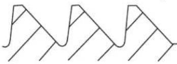
Pure geometric line pattern with no text, numbers, or symbolsDÉTAIL B
Avant 1er Déc. 1991
FILETAGE TRIANGULAIRE 15 CM (6 PO.)

natural_image
Abstract geometric pattern composed of overlapping triangles and lines (no text or symbols)text_image
Technical diagram of a mechanical device with numbered parts, showing internal components and assembly steps.text_image
Technical diagram of a mechanical device with numbered components and an inset close-up view of the top part.Jeu Vertical Requis
text_image
D A 7.72 pouces C B| MODELE | DIM. A DIM. | B DIM. C | DIM. D | |
| TR100C-3 | 100,9 cm 77 | ,5 cm 40, | 8 cm 111, | 1 cm |
| TR140C-3 | 14,9 cm 92 | ,7 cm 47 | cm 125,1 | cm |
| UNITÉ | PIECE NO. | TRITON 100C-3 ET 140C-3 DESCRIPTION |
| 1 27 | 3512 PURGEUR D'AIR AVEC JOINT TORIQUE 23 | |
| 2 27 | 3513 JOINT TORIQUE -VIS DE PURGEUR D'AIR 2 | |
| 3 27 | 3564 CORPS DE PURGEUR D'AIR MANUEL 2 | |
| 4 15 | 5050 MANOMETRE 2 | |
| 5 15 | 4494 JOINT TORIQUE - (3/16 PO. X 2-5/8 PO. - i.d.) 2 | |
| 6 27 | 3564 CORPS DE VANNE - USINÉ 2 | |
| 7 15 | 4575 COUVERCLE - RACCORD 8-1/2 PO. 2 | |
| 8 15 | 4412 ÉCROU - 2 PO. INTERNE 2 | |
| 9 15 | 2509 ANNEAU CARRE - COUVERCLE 23 | |
| 10 15 | 4527 CLÉ - COUVERCLE 8-1/2 PO. 2 | |
| 11 15 | 4856 KIT - COUVERCLE, RACCORD FILETÉ 8-1/2 PO. 2 | |
| 11 15 | 6842 KIT - COUVERCLE, AVEC LE JOINT 8-1/2 PO. 4 | |
| 12 15 | 3430 ENSEMBLE DE RESERVOIR ET PIED TR 100C-3 RACCORD FILETE | |
| 12 15 | 3431 ENSEMBLE DE RESERVOIR ET PIED TR 140C-3 RACCORD FILETE | |
| 13 15 | 4007 ENSEMBLE DE TUYAUTERIE SUPERIEURE TR 100C-3 | |
| 13 15 | 4008 ENSEMBLE DE TUYAUTERIE SUPERIEURE TR 140C-3 | |
| 14 15 | 4005 JOINT TORIQUE - PARKER 2-343 (2 Requis) | |
| 15 15 | 4002 BAGUE D'ECARTEMENT 3 PO. (2 Requis) | |
| 16 15 | 4004 JOINT TORIQUE - PARKER 2-342 (2 Requis) | |
| 17 15 | 4003 BRIDE 3 PO. (2 Requis) | |
| 18 15 | 4001 ADAFTATEUR - BRIDE 3 PO. (2 Requis) | |
| 19 15 | 4009 ENSEMBLE DE TUYAUTERIE INFERIEURE TR100C-3 | |
| 19 15 | 4010 ENSEMBLE DE TUYAUTERIE INFERIEURE TR140C-3 | |
| 20 15 | 4596 PIED - 24 PO. DE DIAMETRE TR100C-3/140C-3 | |
| 21 15 | 2202 ELEMENT LATERAL 9 PO. TR100C-3 (8 Requis) | |
| 21 15 | 4540 ELEMENT LATERAL 12 PO. TR140C-3 (8 Requis) | |
| 22 15 | 4871 CHAPEAU - FILETE 1-1/2 PO. | |
| 23 15 | 2220 ENSEMBLE VIDANGE DE SABLE 2 PO. | |
| 24 27 | 4494 JOINT TORIQUE-(3/16 PO. X 2-5/8 PO. -i.d.) (2 Requis) | |
| 25 15 | 4441 RACORD - TUBE DE PURGE D'AIR | |
| 26 15 | 0041 TUBE - PURGE D'AIR TR100C-3 (23 PO.) | |
| 26 15 | 0042 TUBE - PURGE D'AIR TR140C-3 (27 PO.) | |
| 27 15 | 4018 ENSEMBLE DE TUYAUTERIE DU DIFFUSEUR TR140C-3 (2 Requis) | |
| 28 55 | 2474 VIS- # 10 - 1-1/2 PO. A SIX PANS (2 Requis) | |
| 29 15 | 4599 DIFFUSEUR (2 Requis pour TR100-C3) | |
| 29 15 | 4599 DIFFUSEUR (4 REQUIS POUR TR140-C3) |
FILTRE A SABLE EN FIBRE DE VERRE TRITON™ 100C-3 ET 140C-3
Pièces de Rechange
TR100C-3
TR140C-3
| UNITÉ P | IECE NO. | TRITON 100C-3 ET 140C-3DESCRIPTION |
| 30 15 | 0035 FILTRE - ELC/TR | |
| 31 19 | 0058 MANOMETRE, 1⁄4 PO. PSI 1 | |
| 32 15 | 4581 BOUTON TR OVALE 3 | |
| 33 15 | 4582 RESSORT TR OVALE 3 | |
| 34 15 | 4579 PONT TR OVALE 3 | |
| 35 15 | 4576 COUVERCLE OVALE 3 | |
| 36 15 | 6841 KIT - COUVERCLE OVALE TRITON 1 3 |