LeisureTime LTP750 - Water pump Pentair - Free user manual and instructions
Find the device manual for free LeisureTime LTP750 Pentair in PDF.

| Product Type | Water Pump |
| Brand | Pentair |
| Model | LeisureTime LTP750 |
| Power Rating | 750 W |
| Voltage | 115 V |
| Frequency | 60 Hz |
| Amperage | 6.5 A |
| Max Flow Rate | 3500 GPH |
| Max Head | 28 ft |
| Inlet/Outlet Size | 1.5 in NPT |
| Housing Material | Thermoplastic |
| Impeller Material | Engineering Plastic |
| Seal Type | Mechanical Seal |
| Thermal Protection | Automatic Reset |
| Suction Capability | Self-Priming |
| Application | Pool Filtration, Water Circulation |
| Dimensions (L x W x H) | 12.5 x 8.0 x 10.5 in |
| Weight | 18 lb |
| Certifications | ETL, CSA |
| Warranty | 2 Years |
Frequently Asked Questions - LeisureTime LTP750 Pentair
User questions about LeisureTime LTP750 Pentair
0 question about this device. Answer the ones you know or ask your own.
Ask a new question about this device
Download the instructions for your Water pump in PDF format for free! Find your manual LeisureTime LTP750 - Pentair and take your electronic device back in hand. On this page are published all the documents necessary for the use of your device. LeisureTime LTP750 by Pentair.
USER MANUAL LeisureTime LTP750 Pentair
natural_image
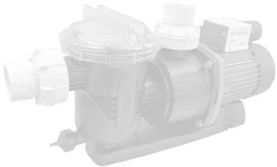
Exterior view of a PENTAIR electric pump with black and teal casing, no visible text or symbols on the device itself.Should the installer or owner be unfamiliar with the correct installation or operation of this type of equipment you should contact the distributor/manufacturer for the correct advice before proceeding with the installation or operation of this product. The pump operator or owner must be provided with this owner's manual.
TABLE OF CONTENTS
Features and Benefits
Page 3
Technical Information 4
Model Data 4
Hydraulic Performance 5
Dimensions 5
Installation 6
Plan the position of the pump 6
Piping 7
Pool Outlets 7
Electrical 8
Equipotential Bonding 8
Operation 9
Priming the Pump 9
Solar Operation 10
Service & Maintenance 12
Troubleshooting 13
Troubleshooting Guide 13
Replacement Parts 15 - 16
natural_image
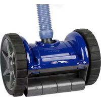
Exterior view of a mechanical pump assembly (no visible text or symbols)Great Value Pump Ideal For Small To Medium Pools
The range of LeisureTime pool pumps have been purposefully designed to provide maximum performance and corrosion resistance. Robust and designed for Australia's harsh conditions, LeisureTime pumps offer exceptional value.
The great economical LeisureTime inground ground pool pumps are ideal for small to medium in-ground pool systems. Sized from 1/2 to 1.5Hp they are purposefully designed to provide maximum performance at a realistic cost with key features and highlighted benefits including:
• Self-aligning barrel unions.
• Efficient, heavy-duty motor.
• Elevated motor foot.
- Marine-grade, stainless steel shaft and epoxy-coated end-shield for maximum corrosion protection.
• Large hair and lint pot with transparent lid and self-lubricating o-ring.
• 2 year warranty.*
Model Data
| RPM: | 2850RPM |
| Electrical Rating: | 230-240V 50Hz single phase |
| Rated Current (A): | LTP400(S): 2.7LTP550(S): 3.5LTP750(S): 4.3LTP1100: 5.4 |
| Input Power ( P_1 ): | LTP400(S): 585WLTP550(S): 785WLTP750(S): 930WLTP1100: 1200W |
| Output Power ( P_2 ): | LTP400(S): 400WLTP550(S): 550WLTP750(S): 700WLTP1100: 900W |
| IP Rating: | IPX5 |
| Inlet (Suction): | ABS Barrel Union to suit 40mm* PVC pressure pipe to AS/NZS 1477 |
| Outlet (Discharge): | ABS Barrel Union to suit 40mm PVC pressure pipe to AS/NZS 1477 |
| Maximum Total Head: | 20m |
| Water Temperature Range: | 5°C - 40°C |
| Maximum Ambient temperature: | 50°C |
| Recommended pH Range: | 7.2 - 7.8 (Guide Only) |
| Motor: | TEFC, 2-Pole, Brushless Induction Motor |
| Protection: | Over temperature, locked rotor, over current. |
| Supply cord: | 10A, H07RNF, 2m. |
*Fits to 50mm AS/NZS pressure pipe spigot. Use a 50mm coupling or 50mm elbow for connection.
Hydraulic Performance
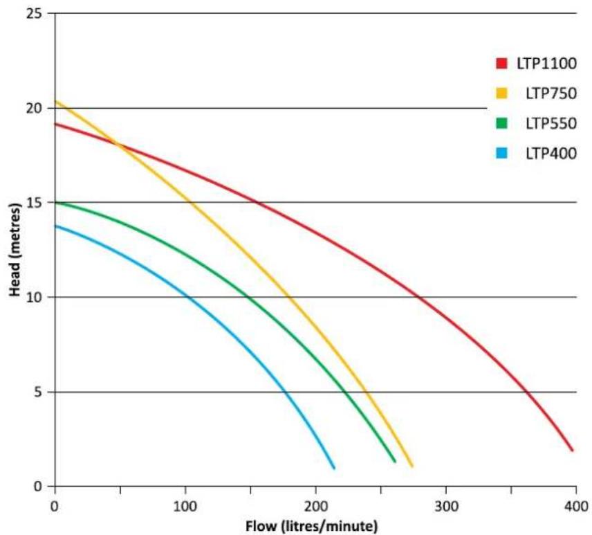
line
| Flow (litres/minute) | LTP1100 | LTP750 | LTP550 | LTP400 | | --------------------- | ------- | ------ | ------ | ------ | | 0 | 19.2 | 20.3 | 15.0 | 13.8 | | 200 | 13.5 | 8.5 | 6.0 | 3.5 | | 400 | 2.0 | 1.0 | 1.5 | 0.5 |Dimensions
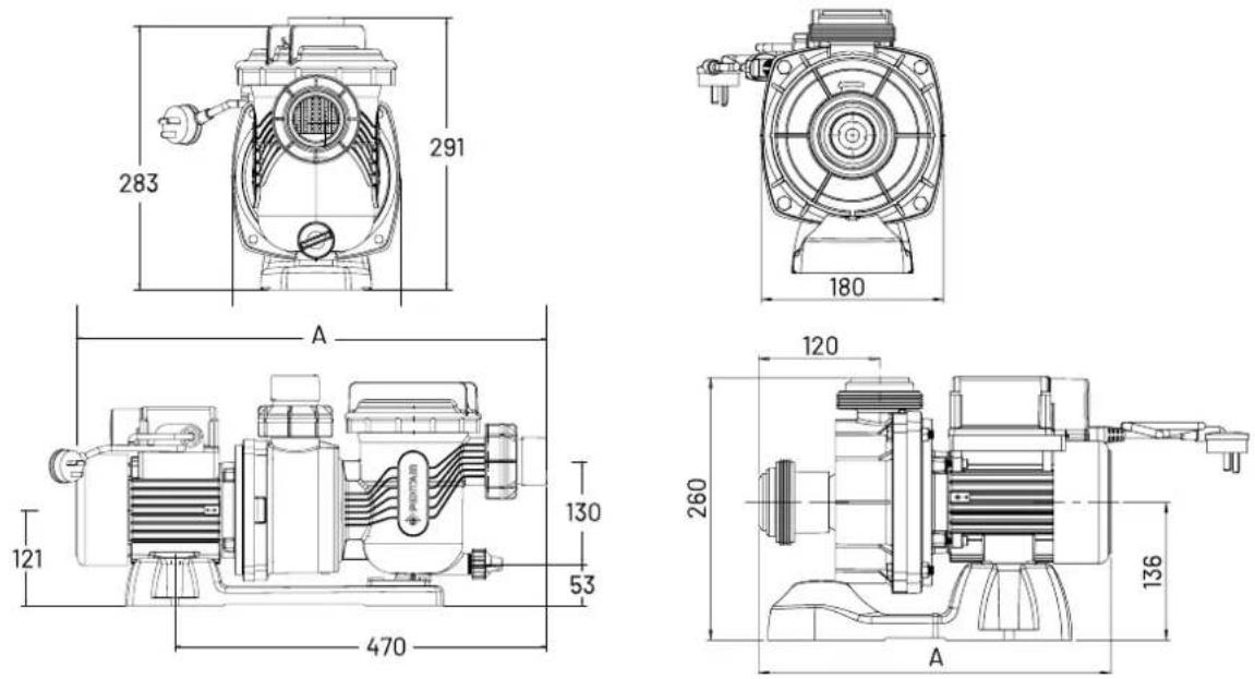
| Pump Model | LTP400 | LTP550 | LTP750 | LTP1100 |
| A(mm) | 526 | 535 535 583 | ||
| LTP400S LTP400S LTP750S | ||||
| 347 356 356 | ||||

The pump must be installed and serviced by a suitably qualified person in order to avoid hazard. Incorrectly installed or tested equipment may fail, causing severe injury or property damage.

These instructions are a guide only. Should you the installer or owner of the product be unfamiliar with the correct installation or operation of this product you should contact a suitably qualified person for advice.

Do not connect system to high pressure or mains water system.

This pump is not intended for use by persons (including children) with reduced physical, sensory or mental capabilities, or lack of experience and knowledge, unless they have been given supervision or instruction concerning use of the appliance by a person responsible for their safety.

Children should be supervised to ensure that they do not play with the pump.

The LeisureTime Poll Pump is electrically connected. Ensure that it is isolated from electrical supply during installation and any subsequent service work.
1. Plan the position of the pump

For best performance, allow pump suction inlet height to be as far below water level as possible and allow the use of short, direct suction pipe with minimum bends (to reduce friction losses).
a. Have enough ventilation to keep ambient temperature below the motor's rated ambient temperature whenever the pump is running. If installed in an enclosure/pump house, the enclosure must have adequate ventilation (200sq.cm min, inlet & outlet) and air circulation. Allow 200mm to keep rear of motor clear.
b. Have adequate floor drainage to prevent flooding and be protected from excess moisture.
c. Be solid, level, rigid and vibration free.
d. To reduce vibration and pipe stress, bolt pump to mount. Fixing holes accept 12mm fasteners.
e. Be within 2m of a power outlet for electrical connection (refer to AS/NZS 3000 for rules regarding connection of electrical equipment in pool zones).
f. Allow adequate access for servicing pump and piping.
2. Piping

For best performance, allow pump suction inlet height to be as far below water level as possible and allow the use of short, direct suction pipe with minimum bends (to reduce friction losses).
a. Use only Australian Standard PVC pressure pipe. For best performance use at least 40mm diameter pipe for all connections to the pump. Never use a suction pipe smaller than pump suction connections (40mm) and use larger pipe for long suction distances.
b. To avoid stress on the pump, support both suction and discharge pipes independently. Place these supports as close to the pump as possible.
c. To avoid a strain left by a gap at the last connection, start all piping at the pump and run pipe away from the pump.
3. Pool Outlets

text_image
DANGER Hazardous suction. Can trap hair or body parts, causing severe injury or death. Do not block suction.a. The pump suction system must provide protection against hazard of suction entrapment or hair entrapment/entanglement. The pool outlet piping must be in accordance with the latest AS1926.3 standard.
b. Suction outlet covers and skimmers must have been tested and found to comply with the latest AS1926.3 standard or ASME/ANSI specification for Suction Fittings.
4. Electrical

Do not use extension leads as they are unsafe in and around the Pool Zone.

Hazardous voltage. Can shock, burn or cause death.
To avoid dangerous or fatal electrical shock, turn OFF power to pump and remove plug from outlet before working on electrical connections.
a. Electrical installation shall be in accordance with the national wiring rules (AS/NZS 3000) taking into account its ratings (Class I, IPX5). The pump is supplied with a standard Australian 10 amp plug and 2 metres of cord. Select the correct Pool Zone for installation.
b. An RCD with maximum rated residual current of 30mA is required for the power supply to the pump. Additionally, if a suitable socket outlet is not available a weatherproof socket must be installed by an electrician in a suitable location. RCD tripping indicates an electrical problem. If RCD trips and will not reset have a qualified electrician inspect and repair electrical system.
c. Incorrect voltage can cause fire or seriously damage pump and voids warranty.
d. Voltage at pump must not be more than 6% above or 10% below motor nameplate rated voltage or pump may overheat, causing overload tripping and reduced component life. If voltage is less than 90% or more than 106% of rated voltage when pump is running at full load, consult the power company.
5. Equipotential bonding
If equipotential bonding is required, connect all metal parts of the swimming pool or spa structure and to all electrical equipment, metal conduit, and metal piping in accordance with the wiring rules. Run a wire from the equipotential bonding terminal on the pump (bottom, left motor bolt with serrated washer) to the pool bonding structure.
This pump is classified as; Double Insulated to Water Circuit.
Priming the pump

It is not necessary to lubricate the oring. The original equipment 0-ring contains a permanent internal lubricant.
a. Before removing trap lid, SWITCH OFF POWER SUPPLY to pump.
b. CLOSE SHUT-OFF VALVES on suction and discharge pipes, if present.
c. Remove the trap lid (turn anti-clockwise).
d. Fill trap tank with water.
e. Check the lid o-ring and sealing surface, ensure there is no dust or debris on either, and replace the lid (turn clockwise to tighten by hand only - no wrenches!).
f. Open the shut-off valves on the suction and discharge pipes, if present.
g. Release all air from filter, pump and piping system (refer filter owner's manual). In a flooded suction system (water source higher than pump), pump will prime itself when suction and discharge valves are opened and air is released.
h. Switch on power to the pump to start.
i. Pump should start to prime now. Priming time will depend on vertical height of suction lift and horizontal length of suction piping but is generally between 30 seconds to 3 minutes under normal installation conditions.
*Should the pump not prime, ensure that all valves are open, lint trap is clear of debris and suctions and suction pipe end is submersed in water, and that there are no leaks in suction pipe. See troubleshooting guide.

NEVER run pump dry. Running pump dry may damage seals, causing leakage and flooding. Fill pump with water before starting motor.

Freezing conditions will damage the unit, as water expands as it freezes. Ensure that the pump is located so that it is not prone to freezing, or ensure that the product is disconnected and dried of water during cold conditions.

Trapped air in system can cause explosion. Ensure all air is out of the system before operating or testing equipment.

Fire and burn hazard. Modern motors run at high temperatures. To reduce the risk of fire, do not allow leaves, debris, or foreign matter to collect around the pump motor. To avoid burns when handling the motor, let it cool for at least 20 minutes before trying to work on it.

Small children using pool must ALWAYS have close adult supervision.

Pump suction is hazardous and can trap and drown or disembowel bathers. Do not use or operate pump, pool/spas if a suction outlet cover is missing, broken, or loose. Follow the guidelines below for a pump installation which minimises risk to users of pool and spas.

NEVER tighten or loosen trap lid while pump is operating.
Solar Operation
Solar pump installation
The LeisureTime Pool Pump can be used as a Solar Pump. There are two typical solar configurations; as a separate system, where the pump is plumbed separately to the filtration system OR as a boosted system running from the filtration system.
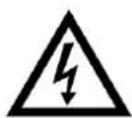
Separate System
- Only use the LTP pool pump in this configuration, not the LTPS pool pump. The LTP pump has an integrated basket which adds protection against debris blocking the system.
- Locate the pump as per the instructions on pages 6-9.
- The pump must be installed as per Australian standards. Use two suctions, with separation and covers complying with AS1926.3.
- Install the included 'clacker' on the outlet of the pump. The purpose of the 'clacker' is to provide protection against water running backwards through the pump rapidly and spinning the impeller backwards.
- A check valve must be installed on the outlet of the pump between the pump and the solar input. The check-valve shall allow drain down of the solar pipes. A 6mm hole can be drilled into the flap of the non-return valve to achieve this.
- Complete installation instructions as per solar heating system guidelines.
Plumbing diagram separate
text_image
TO SOLAR FROM SOLAR CHECK VALVE WITH DRAIN HOLE CLACKER INSTALLED ON OUTLET TO POOL/SPA FROM POOL/SPABoosted System
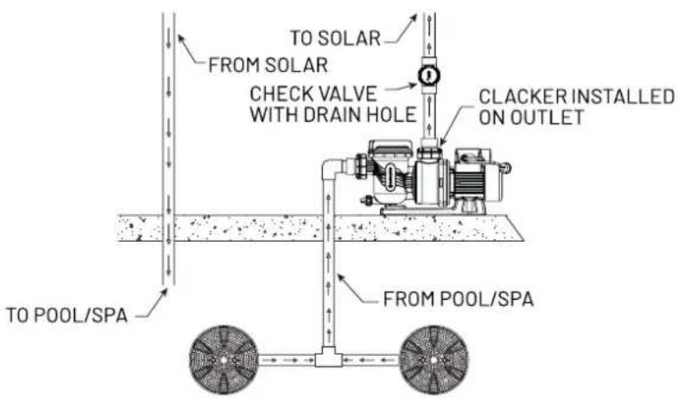
-
Only use the LTPS pool pump in this configuration, not the LTP pool pump. The LTPS pump is design as a solar booster pump.
-
Locate the pump as per the instructions on pages 6-9.
-
The pump is to be installed after the filter.
-
A bypass pipe shall be installed between the pump suction and solar heating outlet.
-
Install the included 'clacker' on the outlet of the pump. The purpose of the 'clacker' is to provide protection against water running backwards through the pump rapidly and spinning the impeller backwards.
-
A check valve must be installed on the outlet of the pump between the pump and the solar input. The check-valve shall allow drain down of the solar pipes. A 6mm hole can be drilled into the flap of the non-return valve to achieve this.
-
Complete installation instructions as per solar heating system guidelines.
Plumbing diagram booster
text_image
SALT CHLORINATOR OR FEEDER FROM SOLAR CHECK VALVE WITH DRAIN HOLE TO SOLAR FILTER CLACKER INSTALLED ON OUTLET FILTER PUMP LTPS SOLAR BOOST PUMP TO POOL FROM POOL
To avoid dangerous or fatal electrical shock hazard, turn OFF power to pump and remove plug from power outlet before working on pump.

Do not operate pump with trap basket missing or damaged.
- It is essential for the longevity of the pump that regular service and maintenance be carried out. The LeisureTime Pool Pump incorporates high velocity moving parts and is pumping water containing harsh pool chemicals. Some parts which will wear during the normal operation and expected life of the pump.
FREQUENCY
Inspect trap basket, and empty of any leaves and other debris. Leaves and other debris that collects in basket will choke off water flow through the pump and reduce efficiency and performance. See below instructions on cleaning the trap.

Check the pump to ensure no water is leaking from inlet and outlet joints, whilst pump is operating. If leaks are noticed, clean and grease the o-rings or replace if necessary.

Clean area around pump and ensure there are no leaves or debris which could become a fire hazard or choke the motor fan.

Check that there are no leaks from under the pump. If there are, this could be a sign of a leaking mechanical seal. Call a Pentair Service Agent immediately, to prevent damage to the motor.

Check pump and motor for insects and pest infestations and ensure that motor fins are clean of dust and dirt. Clean if necessary.
Follow instructions below to clean trap:
- Switch off power to pump, close valves in suction and discharge, and release all pressure from system before proceeding.
- Remove trap cover (turn counter clockwise). If necessary, tap handles gently with a rubber mallet.
- Remove strainer basket and clean. Ensure all holes in basket are clear, flush basket with water and replace in trap with large opening at pipe connection port (between ribs provided). If basket is replaced backwards, the cover will not fit on trap body. To clean transparent cover, use water and neutral soap only. Do not use solvents.
- Clean and inspect lid o-ring; reinstall on trap. Clean O-ring groove on trap body and replace cover. To help keep cover from sticking, tighten hand tight only.
- Prime pump (refer priming instructions).

The pump should only be serviced by certified Pentair service agents. For best results and to ensure warranty is not void, insist on use of only genuine Pentair service parts.

To avoid dangerous or fatal electrical shock hazard, turn OFF power to pump and remove plug from power outlet before working on pump.

The power supply cord has a type 'Y' attachment and if service is required to the power cord, it must be replaced with the specialised power cord assembly by Pentair Water service agent or similarly qualified personnel in order to avoid a hazard. Warranty is void if unauthorised modifications are made to any component.
Troubleshooting Guide
| SYMPTOM CAUSE REMEDY | ||
| Low water pressure, low flow from pump. | Suction leaks / lost prime. | Pump must be primed; make sure that the pump casing and strainer are full of water. Refer priming instructions.Make sure there are no leaks in suction piping and ensure all o-rings are present and clean.Make sure suctions pipe inlet is well below the water level to prevent pump from sucking air.Suction lift of 3 to 6 metres will reduce performance. Suction lift of more than 6 metres will prevent pumping and cause pump to lose prime. In either instance, move the pump closer (vertically) to water source. Ensure that the suction pipe diameter is large enough. |
| Clogged pipe / strainer / impeller / filter system. | Ensure trap is not clogged with debris; clean basket and/or filter.Make sure that the impeller is not clogged. This should be checked by qualified personnel only.Pump may be trying to push too high a column of water. If so, a higher pressure pump is required. | |
| No water coming from pump (pump is working). | Air ingress to system. | • Prime the pump. Check that there are no air leaks in the suction piping or fittings. Ensure the strainer lid is airtight and fitted securely. Ensure all o-rings are present. |
| Pump does not work. | Motor fault. • Refer to motor fault codes. | |
| No power at outlet. • Use another electrical appliance that is known to work to check power outlet. | ||
| Blown fuse / Circuit breaker. | • Check and call electrician if necessary. | |
| Water leaking from between the casing and motor. | Casing bolts are not tightened sufficiently; worn mechanical seal requires replacing. | • Switch off the power to the pump. Tighten the casing bolts or replace the mechanical seal as required. |
Should problems persist, contact your nearest Pentair Water Service Agent.
LeisureTime High Performance Pump
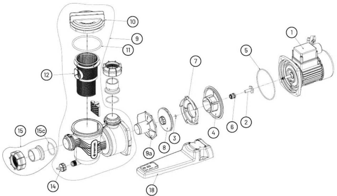
text_image
Exploded view diagram of a mechanical device with numbered parts for identificationItem Description Part No. Part No. Part No. Part No.
| LTP400LTP550LTP750LTP1100 | |||||
| 1 | MOTOR | 800738 | 800442 | 800442 | 801211 |
| 2 | SHAFT SLEEVE (INCLUDES ITEM 2&3) | 800894K | 800894K | 800894K | 800895K |
| 3 | O-RING SHAFT SLEEVE (10 Pack) | 702196K | 702218K | ||
| 4 | BAFFLE | 302060K | 302060K | 302060K | 305300 |
| 5 | ORING-CASING | 702206K | 702206K | 702206K | 702206K |
| 6 | MECHANICAL SEAL (25 Pack) | 702789K (800901) | 700270K (800900) | ||
| SEAL KIT (INCLUDES ITEM 2,3,5 & 6) | 800582K | 800582K | 800582K | 800583 | |
| 7 | DIFFUSER | 302200K | 302200K | 302190K | 303460K |
| 8 | IMPELLER | 504593K | 510803K | 504823K | 506840K |
| 9 | CASING ASSEMBLY | 800410 | 800410 | 800410 | 800410 |
| 9A | SEPERATOR PLATE | 408610 | 408610 | 408610 | 412140 |
| 10 | LID (INCLUDES O-RING) | 800897K | 800897K | 800897K | 800897K |
| 11 | ORING-LID (4 Pack) | 702208 (702208K) | |||
| 12 | BASKET | 302310 | 302310 | 302310 | 302310 |
| 13 | FINGER GUARD | 508210 | 508210 | 508210 | 508210 |
| 14 | DRAIN PLUG | 504605 | 504605 | 504605 | 504605 |
| 15 | BARREL UNION KIT (2pk) | 800714 | 800714 | 800714 | 800714 |
| 15c | ORING-SWIVEL BARREL UNION | 702193 | 702193 | 702193 | 702193 |
| 18 | BASE & SCREW KIT | 800532 | 800532 | 800532 | 800532 |
| NON-RETURN CLACKER | 604021K | 604021K | 604021K | 604021K | |
| PUMP FASTENERS KIT | 801278 | 801278 | 801278 | 801278 | |
LeisureTime Solar & AGP Pumps
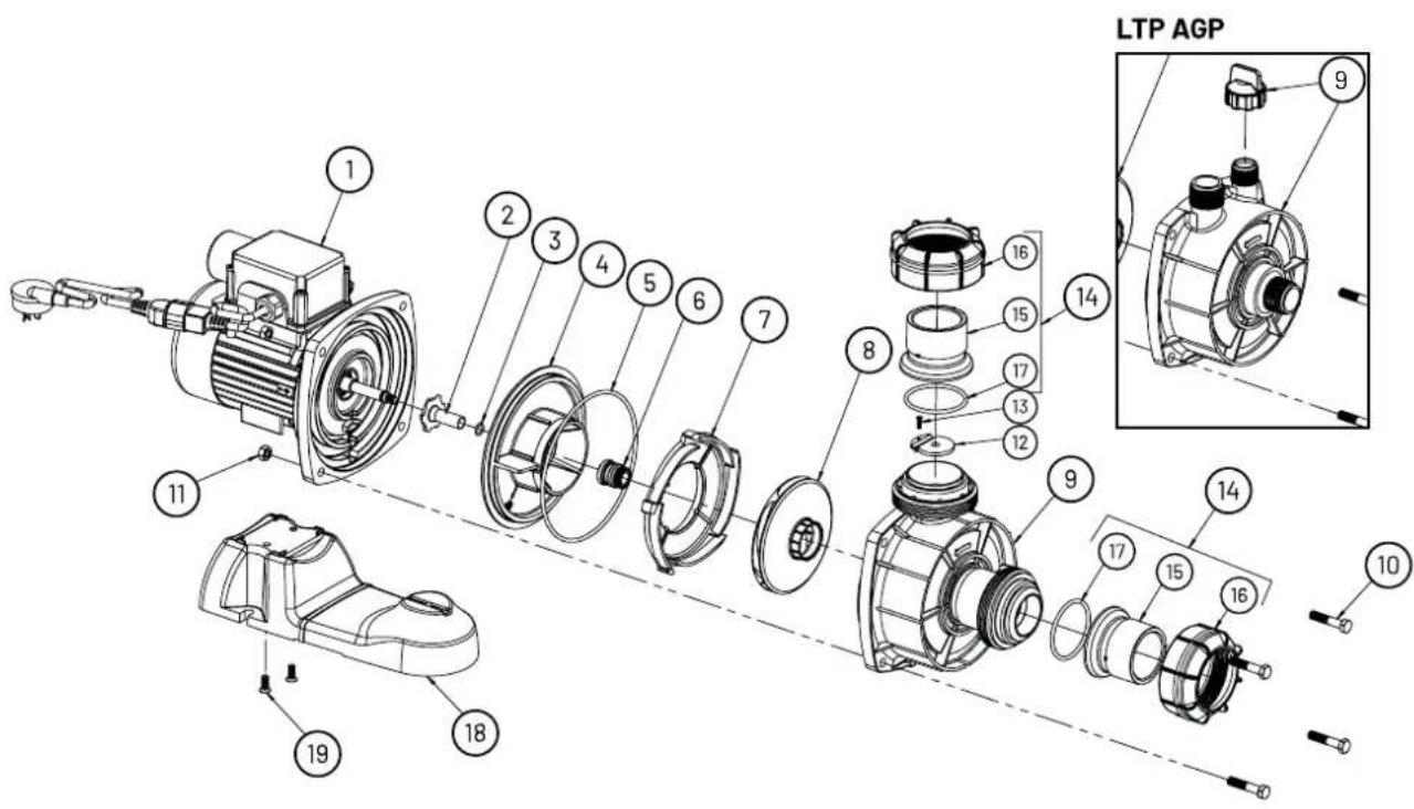
text_image
LTP AGP 9 16 15 14 17 13 12 8 9 14 17 15 16 10 11 19 18Item Description Part No. Part No. Part No.
| LTP400SLTP550SLTP750S | ||||
| 1 MOTOR 800738 800442 800442 | ||||
| 2 | SHAFT SLEEVE & O-RING KIT (INCLUDES ITEM 2 & 3) | 800894K | 800894K | 800894K |
| 3 | O-RING SHAFT SLEEVE (10 PACK) | 702196K | 702196K | 702196K |
| 4 | BAFFLE | 302060K | 302060K | 302060K |
| 5 | ORING-CASING | 702206K | 702206K | 702206K |
| 6 | MECHANICAL SEAL | 702789K | 702789K | 702789K |
| SEAL KIT (INCLUDES ITEM 2,3,5 & 6) | 800582K | 800582K | 800582K | |
| MECHANICAL SEAL (25 PACK) | 800901 | 800901 | 800901 | |
| 7 | DIFFUSER | 302200K | 302070 | 302190K |
| 8 | IMPELLER | 504593K | 510803K | 504823K |
| 9 | CASING & B/UNION ASSEMBLY LTP SOLAR | 707426 | 707426 | 707426 |
| 9 | CASING ASSEMBLY LTP AGP | 512646 | 512647 | 512647 |
| 10 | SCREW 5/16inW x 1.1/2in HWF Hd | See Pump Fasteners Kit | ||
| 11 | NUT 5/16inW HEX Steel | See Pump Fasteners Kit | ||
| PUMP FASTENERS KIT (INCLUDES ITEM 10 & 11)x4 | 801278 | 801278 | 801278 | |
| 12 | CLACKER ASSEMBLY (INCLUDES ITEM 12 & 13) | 800904K | 800904K | 800904K |
| 14 | BARREL UNION ASSEMBLY (INCLUDES ITEM 15, 16 & 17)x2 | 800714 | 800714 | 800714 |
| 17 | ORING - BARREL UNION | 702193 | 702193 | 702193 |
| 18 | BASE & SCREWS KIT (INCLUDES 18 & 19x2) | 304600K | 304600K | 304600K |
| PRIMING CAP (AGP ONLY) | 504605 | 504605 | 504605 | |
IMPORTANT
Please attach your sales invoice/docket here as proof of purchase should warranty service be required. Please do not return warranty form to Pentair Australia - Retain for your records.
| PURCHASED FROM: |
| PURCHASE DATE: |
| SERIAL NO: |
| MODEL NO: |

PENTAIR
1-21 Monash Drive | Dandenong South, VIC 3175 | Australia | 1300 137 344 | pentairpool.com.au
Information contained here-in remains the property of Pentair Australia Pty Ltd under Australian copyright law. Content may not be reproduced or transmitted without our prior written permission. All indicated Pentair trademarks and logos are property of Pentair. Third party registered and unregistered trademarks/logos are the properties of their respective owners.
Disclaimer: Pentair reserves the right to change product specifications and products details. Product images are for reference purposes only and may not represent the actual/current product.
©2022 Pentair. All rights reserved.