
NK30B3000US - Range hood SAMSUNG - Free user manual and instructions
Find the device manual for free NK30B3000US SAMSUNG in PDF.
| Brand | Samsung |
| Model | NK30B3000US |
| Product Type | Under-cabinet Kitchen Range Hood |
| Color | Stainless Steel |
| Dimensions (W x D x H) | 76 cm x 47.5 cm x 15 cm (approx) |
| Weight | Approximately 15 kg |
| Power Supply | 120V AC, 60Hz, 15A |
| Power Consumption | 38W |
| Lighting | Integrated LED |
| Controls | Push buttons (light and fan on/off) |
| Number of Speeds | 1 (on/off) |
| Ventilation Type | External venting (7" round duct) or recirculation (optional charcoal filter) |
| Duct Diameter | 7 inches (17.8 cm) |
| Grease Filter | Metallic, dishwasher safe |
| Charcoal Filter | Optional (part no. DG81-03610A), lifespan ~6 months |
| Minimum Mounting Height | 61 cm (electric range) / 76 cm (gas range) |
| Warranty | 1 year parts and labor |
| Certifications | FCC, IC, ADA compliant |
| Material | Stainless Steel |
| Installation Type | Under cabinet |
| Included Parts | Hood with fan and LED lights, grease filter, screws, Torx adapter, mounting bracket |
Frequently Asked Questions - NK30B3000US SAMSUNG
User questions about NK30B3000US SAMSUNG
0 question about this device. Answer the ones you know or ask your own.
Ask a new question about this device
Download the instructions for your Range hood in PDF format for free! Find your manual NK30B3000US - SAMSUNG and take your electronic device back in hand. On this page are published all the documents necessary for the use of your device. NK30B3000US by SAMSUNG.
USER MANUAL NK30B3000US SAMSUNG
Important Safety Instructions 3
Electrical Requirements 5
Venting Requirements (ducted models only) 5
Venting Methods 5
Cold Weather Installations 5
Makeup Air 5
Installation Requirements 5
Tools and Parts 6
Dimensions and Clearances 6
Installation Instructions 7
Venting Methods 7
Prepare the location 7
Installation Instructions 7
Prepare Range Hood 8
Mark Hole Locations 8
Mark and Cut Vent Opening 9
Drill Electrical Opening 9
Prepare Range Hood Vents 9
Attach Vent Damper or Transition 9
Mounting the Hood 10
Connect Vent System 10
Electrical Connection 10
Completing the Installation 10
Range Hood Use and Care 11
Range Hood Description 11
Range Hood Controls 11
Cleaning 11
Metal Grease Filter 11
Charcoal Filter 11
Replacing the LED Lamp 11
Range Hood for ADA Compliance 12
warranty (USA) 13
warranty (Canada) 14
APPROVED FOR RESIDENTIAL APPLIANCES
READ AND SAVE THESE INSTRUCTIONS
PLEASE READ ENTIRE INSTALLATION GUIDE BEFORE PROCEEDING. INSTALLATION MUST COMPLY WITH ALL LOCAL CODES.
IMPORTANT: Save these Instructions for the Local Electrical Inspector's use.
INSTALLER: Please leave these Instructions with this unit for the owner.
OWNER: Please retain these instructions for future reference.
Symbols used in this manual

WARNING
Hazards or unsafe practices that may result in severe personal injury or death.

CAUTION
Hazards or unsafe practices that may result in electric shock, personal injury, or property damage.

NOTE
Useful tips and instructions.
These warning icons and symbols are here to prevent injury to you and others.
Please follow them explicitly. After reading this section, keep it in a safe place for future reference.

WARNING
Turn off power circuit at service panel and lock out panel before wiring this appliance.
Requirement 120 VAC, 60 Hz. 15 or 20 A Branch Circuit

WARNING
Cancer and Reproductive Harm - www.P65Warnings.ca.gov
1. FCC Notice

CAUTION
FCC CAUTION: Any changes or modifications not expressly approved by the party responsible for compliance could void the user's authority to operate the equipment.
This device complies with Part 15 of FCC Rules. Operation is Subject to following two conditions:
1) This device may not cause harmful interference, and
2) This device must accept any interference received including interference that cause undesired operation.
For products sold in the US and Canadian markets, only channels 1\~11 are available. You cannot select any other channels.
FCC STATEMENT:
This equipment has been tested and found to comply within the limits for a Class B digital device, pursuant to part 15 of the FCC Rules. These limits are designed to provide reasonable protection against harmful interference in a residential installation.
This equipment generates, uses, and can radiate radio frequency energy and, if not installed and used in accordance with the instructions, may cause harmful interference to radio communications.
However, there is no guarantee that interference will not occur in a particular installation. If this equipment does cause harmful interference to radio or television reception, which can be determined by turning the equipment off and on, the user is encouraged to try to correct the interference by one or more of the following measures:
- Reorienting or relocating the receiving antenna
- Increasing the separation between the equipment and receiver
- Connecting the equipment to an outlet that is on a different circuit than the radio or TV.
- Consulting the dealer or an experienced radio/TV technician for help.
FCC RADIATION EXPOSURE STATEMENT:
This equipment complies with FCC radiation exposure limits set forth for an uncontrolled environment. This equipment should be installed and operated so there is at least 8 inches (20 cm) between the radiator and your body. This device and its antenna(s) must not be co-located or operated in conjunction with any other antenna or transmitter.
2. IC Notice
The term “IC” before the radio certification number only signifies that Industry Canada technical specifications were met. Operation is subject to the following two conditions: (1) this device may not cause interference, and (2) this device must accept any interference, including interference that may cause undesired operation of the device.
This Class B digital apparatus complies with Canadian ICES-003. For products sold in the US and Canadian markets, only channels 1\~11 are available. You cannot select any other channels.
IC RADIATION EXPOSURE STATEMENT:
This equipment complies with IC RSS-102 radiation exposure limits set forth for an uncontrolled environment. This equipment should be installed and operated so there is at least 8 inches (20 cm) between the radiator and your body. This device and its antenna(s) must not be co-located or operated in conjunction with any other antenna or transmitter.

WARNING
TO REDUCE THE RISK OF FIRE, ELECTRIC SHOCK, OR INJURY TO PERSONS, OBSERVE THE FOLLOWING PRECAUTIONS:
■ Use this unit only in the manner intended by the manufacturer. If you have questions, contact the manufacturer.
■ Before servicing or cleaning the unit, switch the power off at the service panel and lock the service panel to prevent power from being switched on accidentally. If the service panel cannot be locked, securely fasten a prominent warning device, such as a tag to the service panel.
■ Installation work and electrical wiring must be done by qualified person(s) in accordance with all applicable codes and standards, including fire-rated construction.
- Sufficient air is needed for proper combustion and exhausting of gases through the flue (chimney) of fuel burning equipment to prevent backdrafting. Follow the heating equipment manufacturer's guideline and safety standards such as those published by the National Fire Protection Association (NFPA), the American Society for Heating, Refrigeration and Air Conditioning Engineers (ASHRAE), and the local code authorities.
■ When cutting or drilling into the wall or ceiling; do not damage electrical wiring and other hidden utilities.
■ Ducted fans must always be vented outdoors.

CAUTION
For general ventilating use only. Do not use to exhaust hazardous or explosive materials and vapors.

CAUTION
To reduce the risk of fire and to properly exhaust air, be sure to duct air outside - do not vent exhaust air into spaces within walls or ceilings, attics or into crawl spaces, or garages.

WARNING
TO REDUCE THE RISK OF FIRE, USE ONLY METAL DUCTWORK.

CAUTION
This appliance is not intended for use by persons (including children) with reduced physical, sensory or mental capabilities, or lack of experience and knowledge, unless they have been given supervision or instruction concerning use of the appliance by a person responsible for their safety.

CAUTION
Children should be supervised to ensure that they do not play with the appliance.

WARNING
TO REDUCE THE RISK OF A RANGE TOP GREASE FIRE:
■ Never leave surface units unattended at high settings. Boilovers cause smoking and greasy spillovers that may ignite. Heat oils slowly on low or medium settings.
■ Always turn the hood ON when cooking at high heat or when flambeing food (i.e. Crepes Suzette, Cherries Jubilee, Peppercorn Beef Flambé).
■ Clean ventilating fans frequently. Grease should not be allowed to accumulate on the fan or filter.
■ Use proper pan sizes. Always use cookware appropriate for the size of the surface element.

WARNING
TO REDUCE THE RISK OF INJURY TO PERSONS IN THE EVENT OF A RANGE TOP GREASE FIRE, OBSERVE THE FOLLOWING PRECAUTIONS: ^a
■ SMOTHER FLAMES with a close fitting lid, cookie sheet, or metal tray, then turn off the burner. BE CAREFUL TO PREVENT BURNS. If the flames do not go out immediately, EVACUATE AND CALL THE FIRE DEPARTMENT.
■ NEVER PICK UP A FLAMING PAN - you may get burned.
■ DO NOT USE WATER, including wet dishcloths or towels - a violent steam explosion can result.
■ Use an extinguisher ONLY if:
- You know you have a class ABC extinguisher, and you already know how to operate it.
– The fire is small and contained in the area where it started.
– The fire department is being called.
- You can fight the fire with your back to an exit.
^a Based on "Kitchen Fire Safety Tips" published by NFPA.

WARNING
To reduce the risk of fire or electrical shock, do not use this fan with any solid-state speed control device.

WARNING
Do not let children near this appliance. Do not let children play with this appliance.
Keep all packaging materials out of children's reach. Properly dispose the packaging materials after this appliance is unpacked.

WARNING
Turn off the hood before opening the filter and be sure to use the filter with the screw fastened.

WARNING
To reduce the risk of injury, do not force vertically on the filter plane and handle while cleaning.

WARNING
Cancer and Reproductive Harm - www.P65Warnings.ca.gov
Read and save these instructions
Electrical Requirements IMPORTANT
Observe all governing codes and ordinances.
It is the customer's responsibility:
To contact a qualified electrical installer.
If codes permit and a separate ground wire is used, it is recommended that a qualified electrician determine that the ground path is adequate.
A copy of the above code standards can be obtained from:
National Fire Protection Association
1 Batterymarch Park
Quincy, MA 02169-7471
CSA International
8501 East Pleasant Valley Road
Cleveland, OH 44131-5575
■ A 120 volt, 60 Hz., AC only, 15-amp, fused electrical circuit is required.
■ If the house has aluminum wiring, follow the procedure below:
-
Connect a section of solid copper wire to the pigtail leads.
-
Connect the aluminum wiring to the added section of copper wire using special connectors and/or tools designed and UL listed for joining copper to aluminum.
■ Follow the electrical connector manufacturer's recommended procedure. Aluminum/copper connection must conform with local codes and industry accepted wiring practices.
■ Wire sizes and connections must conform with the rating of the appliance as specified on the model/serial rating plate. The model serial plate is located behind the filter on the rear wall of the range hood.
■ Wire sizes must conform to the requirements of the National Electrical Code, ANSI/NFPA 70 (latest edition), or CSA Standards C22.1-94, Canadian Electrical Code, Part 1 and C22.2 No. 0-M91 (latest edition) and all local codes and ordinances.
If an electrical connection is accessible, connect the hood to an outlet that complies with current codes and regulations and ensure that the outlet is in a position where the hood can be installed. If an electrical connection is not accessible in the install location (direct connection to the electrical network) or the outlet will not be in a position for installation, place an approved bipolar switch in an accessible position that provides full disconnection under Overvoltage Category III conditions, in accordance with local wiring rules. When the product is connected by a plug to the outlet, the plug must remain visible after installation of the product.
Venting Requirements (ducted models only)
- Vent system must terminate outdoors.
- Do not terminate the vent system in an attic or other enclosed area.
- Do not use a 4" (10.2 cm) laundry-type wall cap.
- Use 7" (17.8 cm) round metal vent or 31/4" x 10" (8.3 x 25.4 cm) rectangular metal vent only. Rigid metal vent is recommended. Plastic or metal foil vent is not recommended.
- The length of the vent system and the number of elbows should be kept to a minimum to provide efficient performance.
For the most efficient and quiet operation:
- Use no more than three 90^ elbows.
-
Make sure there is a minimum of 30" (76.2 cm) of straight vent between the elbows if more than 1 elbow is used.
-
Do not install 2 elbows together.
- Use clamps to seal all joints in the vent system.
- The vent system must have a damper. If the roof or wall cap has a damper, do not use the damper supplied with the range hood.
- Use caulking to seal the exterior wall or roof opening around the cap.
- The size of the vent should be uniform.
Venting Methods
To use the hood's top outlet to vent your hood a 7" (17.8 cm) or larger round vent with a maximum length of 50 ft (15.2 m) vent system is required. These vent system is not included and must be purchased separately.

■ The vent system is optional for this model.
- Flexible vent is not recommended. Flexible vent creates back pressure and air turbulence that greatly reduces performance. The vent system can terminate either through the roof or wall. To vent through a wall, a 90° elbow is needed.
Mounting Height
Mount the hood no less than 24" (61.0 cm) above an electric cooking surface, no less than 30" (76.2 cm) above a gas cooking surface, and no higher than 30" (76.2 cm) above either surface.
Horizontal discharge
A 90° elbow may be installed immediately above the hood.
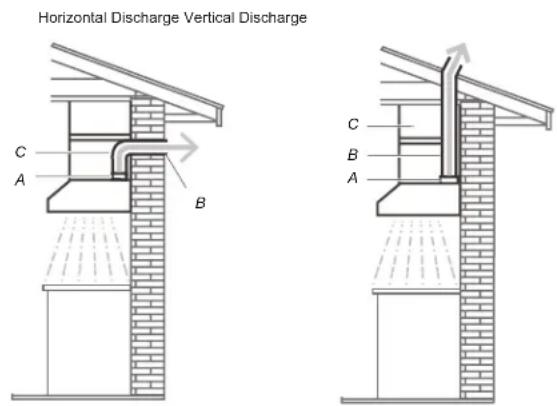
A. 7" (17.8 cm) round vent.
B. Wall cap with damper (not included).
C. 90° elbow
A. 7" (17.8 cm) round vent.
B. Cabinet
C. Roof cap with damper (not included).
Cold Weather Installations
An additional backdraft damper should be installed to minimize backward cold air flow and a thermal break should be installed to minimize conduction of outside temperatures as part of the vent system. The damper should be on the cold air side of the thermal break.
The break should be as close as possible to where the vent system enters the heated portion of the house.
Makeup Air
- When using ventilation systems with greater than specified CFM of air movement, review local building codes as they may require makeup air systems. Consult a HVAC professional for specific requirements for your area as CFM requirements can vary between locales.
- Consult an HVAC professional to select the correct CFM capacity range hood for your application. The CFM capacity depends on the range or cooktop BTU rating, size and location, size of the kitchen and the range hood ductwork in the kitchen.
Installation Requirements
Tools and Parts
Removing the packaging

CAUTION
Remove the carton carefully. Wear gloves to protect against sharp edges.

WARNING
Remove the protective film covering the product before putting into operation.
Parts supplied
- Hood assembly with blower and LED lamps already installed.
- Hardware bag with:
| Part Qty Part Qty | |||
| 5 x 45 mm | 2 | Torx® T10 adapter | 1 |
| 8 x 45 mm | 2 | 4.5x13 mm | 4 |
Tools/Materials required
- Level
- Drill with 18'' (3 mm), 12'' (13 mm) and 114'' (30 mm) drill bits
- Pencil
- Wire stripper or utility knife
- Tape measure or ruler
- Pliers
• Caulking gun and weatherproof caulking compound - Saber or keyhole saw
- Metal snips
- Screwdrivers:
• #2 Phillips - Flat - blade
Parts needed
• Home power supply cable
- 1/2'' (12.7 mm) UL listed or CSA approved strain relief
• 3 UL listed wire connectors
For 7" (17.8 cm) round vented installations
- 7" (17.8 cm) round mental vent system with wall or roof cap
- Vent clamps
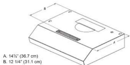
Dimensions and Clearances
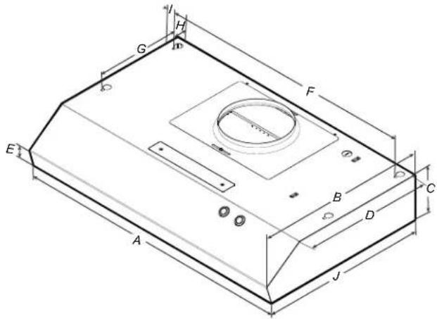
| NK30B3000US/AA | |
| A 30" (76 cm) | |
| B 18 | 34" (47.5 cm) |
| C 5" (12.5 cm) | |
| D 14 12" (36.7 cm) | |
| E 2" (5 cm) | |
| F 27 | ^15/_16" (70.9 cm) |
| G 9" (22.9 cm) | |
| H 1 12" (3.8 cm) | |
| I 1" (2.5 cm) | |
| J | 1818" (46 cm) |
Installation Instructions
We recommend that a qualified technician install the range hood. It is the installer's responsibility to ensure the range hood complies with the installation clearances specified for the product.
- It is recommended that the vent system be installed before the hood is installed.
- If possible, disconnect and move freestanding or slide-in ranges from cabinet openings to provide easier access to the rear wall.
- Before making cutouts, make sure there is proper clearance within the ceiling or wall for the exhaust vent.
-
Confirm that all installation parts have been removed from the shipping carton.
-
Turn off the power at the circuit breaker panel or fuse box.
-
Determine which venting method to use: roof, wall, or non-vented (recirculating).
-
Select a flat surface for assembling the range hood. Place a covering over that surface.
Venting Methods
Outside Top exhaust
Use 7" (17.8 cm) or larger round vent with a maximum length of 50 ft (15.2 m) for vent system.
Use the diagram or the hood as a template and mark the locations for the ductwork, electrical wiring and keyhole screw slots.
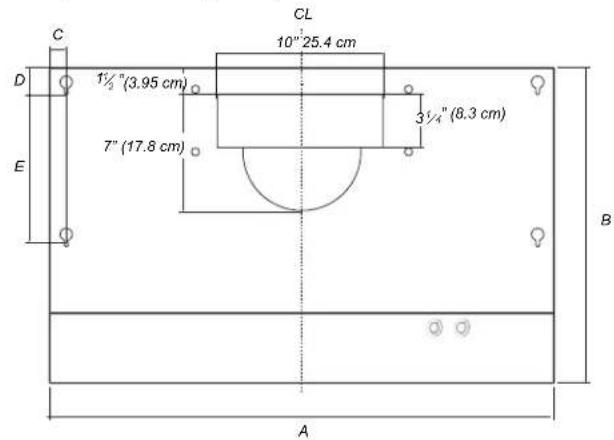
| A 30" (76 cm) | |
| B 18 | 34'' (47.5 cm) |
| C 1" (2.5 cm) | |
| D 1 12'' (3.8 cm) | |
| E 9" (22.8 cm) | |
WARNING
USE TWO OR MORE PEOPLE TO MOVE AND INSTALL THE RANGE HOOD. FAILURE TO DO SO CAN RESULT IN INJURY.
NOTE
Mark the Range Hood knockouts on the wall and make the necessary cutouts before installing the hood.
Prepare the location
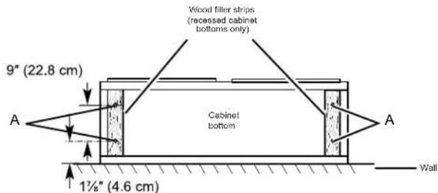
- If cabinet has recessed bottom, add wood filler strips on each side. Install 4 flat head wood screws with washers and nuts to attach filler strips in locations shown.
NOTE
For installations to a surface other than drywall, it is recommended that a qualified contractor determine the anchoring method.
NOTE
Consider use the A measure for 7"(17.8 cm) round transition and B measure for recirculating system.
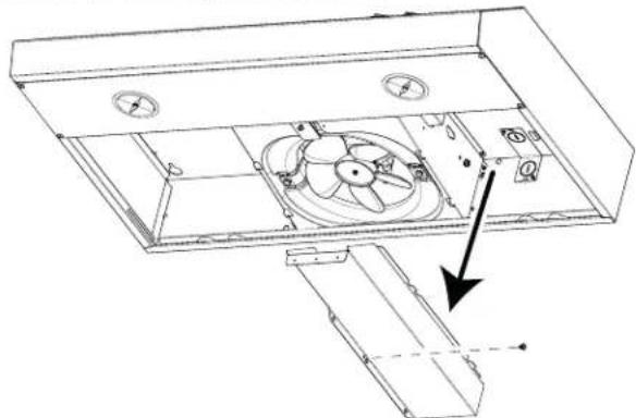
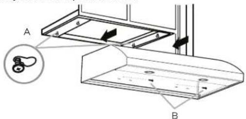
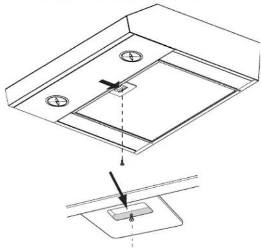
- Remove the grease filter by pulling the filter latch toward the back of the range hood and using a Torx T10 adapter, remove the screw from the filter retainer.
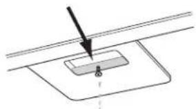
natural_image
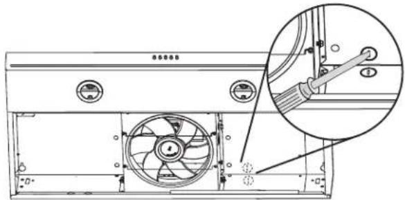
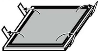
Pure technical diagram showing a downward arrow pointing to a rectangular component with a small hole, without any text or symbols.- Remove the lateral panels by pulling them horizontally to the back of the hood and then release the brackets on the front.
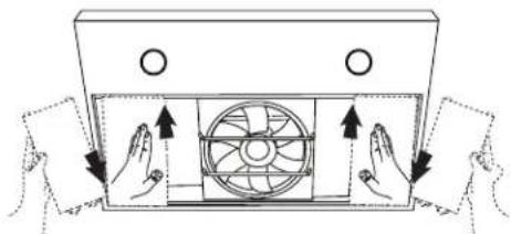
natural_image
Diagram of hands operating a fan inside a cabinet, showing directional arrows (no text or symbols)Installation Instructions
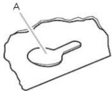
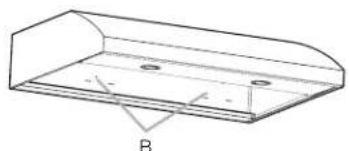
- Using 2 or more people, lift the range hood up under cabinet and determine final location by centering beneath cabinet. Mark on the underside of cabinet the location of the 4 keyhole mounting slots on the range hood (A)

NOTE
Mark the thin area of the slot. On the back wall mark the holes for the security screws (B). Set range hood aside on a covered surface.
natural_image
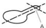
Simple line drawing of a curved object inside a rectangular frame, labeled 'A' with no text or symbols.A. Keyhole slot
- Use 18 (3 mm) drill bit and drill 4 pilot holes.

NOTE
Make the drill holes on the thin area of the slot.
A. Drill pilot hole
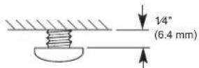
- Install the 4 - .45 cm x 1.3 cm mounting screws in pilot holes. Leave about 14 " (6.4 mm) space between screw heads and cabinet to slide range hood into place.
- Use 125 " (8mm) drill bit and drill 2 pilot holes in the marks for the security screws, then place the drywall anchors.
natural_image
Technical line drawing of a 3D rectangular metal bracket with mounting holes and labeled point B (no text or symbols beyond label)Prepare Range Hood
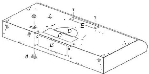
- Set the range hood on its back on a covered surface.
- Unscrew and remove junction box cover
natural_image
Technical line drawing of a mechanical fan assembly with no visible text or symbols- Using a flat head screwdriver, remove the appropriate power supply knockout.
natural_image
Technical line drawing of a mechanical fan assembly with an inset close-up view (no text or symbols)Mark Hole Locations
- Determine and clearly mark a vertical centerline (A) on the wall and cabinet bottom.
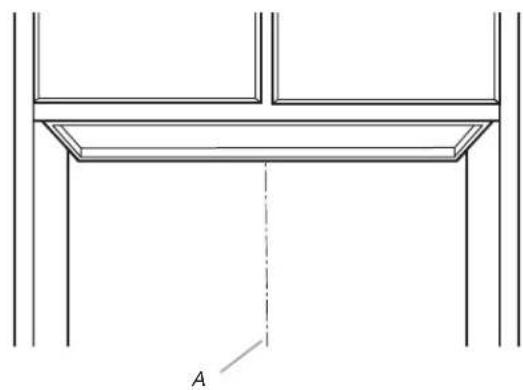
natural_image
Technical line drawing of a structural frame with a dashed line and label 'A' (no text or symbols beyond label)A. Centerline
To wire through top:
- Mark a line distance (A) from the right of the centerline on the underside of the cabinet. Mark the point on this line that is 2" (5.08 cm) from the rear wall. Drill a 18 " (2.2 cm) diameter hole (B) through the underside of the cabinet at this point.
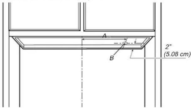
A. 8 2/5" (21.3cm)
To wire through wall:
- Mark a line distance (A) from the right of the centerline on the underside of the cabinet. Mark the point on this line that is 78 " (2.2 cm) from the underside of the cabinet. Drill a 78 " (2.2 cm) diameter hole (B) through the rear wall at this point.
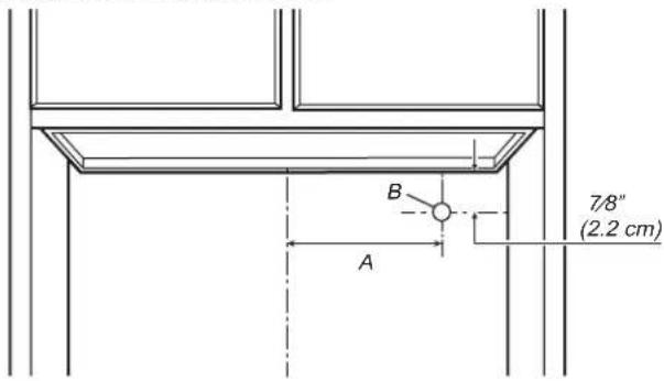
A. 8 2/5" (21.3cm)
Mark and Cut Vent Opening
For a non-vented (recirculating) installation: skip "Mark and Cut Vent Opening" step.
For 7" (17.8 cm) Round Vent System (Roof Venting)
To make a circular vent opening on the underside of the cabinet top:
- Mark a centerline on the underside of the top of cabinet.
- Mark a line 5" (12.8 cm) from the back wall on the underside of the top of cabinet.
- Use a compass or a circle template to draw a circle with a diameter of 712 " (19 cm).
- Use saber or keyhole saw to cut the circular vent opening. Repeat steps 1-3 for the underside of the top of the cabinet.
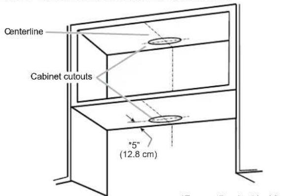
*From wall, not cabinet frame
Drill Electrical Opening
- Using a 114 " (3 cm) drill bit, drill the hole in the dot marked previously at the electrical strain relief.
Prepare Range Hood Vents
Install Strain Relief
- Install a UL listed/CSA approved 12 " (13 mm) strain relief (A).
For non-vented (Recirculating) Installations
Remove the (2) T10 Torx® screws and remove the top, front rectangular vent cover (E). Go to "Electrical Connection" step.
7" (17.8 cm) Round Vent Mounting Plate
- Using (2) short Phillips head screws, install the 7" (17.8 cm) round vent mounting plate (A) over the vent knockouts removed in previous step. Position the wide flange (B) to the front.
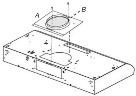
natural_image
Technical line drawing of a mechanical component with labeled parts A and B, showing internal features and mounting holes (no text or symbols beyond labels)Mounting the Hood
- Using 2 or more people, lift the hood into final position. Feed enough electrical wire through the 12'' UL listed or CSA approved strain relief to make connections in the terminal box. Tighten the strain relief screws.
- Position the range hood so that the large end of the keyhole slots are over the mounting screws. Then push the hood toward the wall so that the screws are in the neck of the slots. Install the .5 cm x 4.5 cm mounting screws in drywall anchors.
A. Mounting screws (4)
B. Security screws
- Tighten the mounting screws, making sure the screws are in the narrow neck of slots.
- Tighten the security screws to the wall.
- For direct wire installations, run the home power supply cable according to the National Electric Code or CSA standards and local codes and ordinances. There must be enough wiring from the fused disconnect (or circuit breaker) box to make the connection in the range hood electrical terminal box.

NOTE
Do not reconnect power until the installation is complete.
OPTIONAL: If you prefer, bend the rear tabs against the rear of the range hood and attach to the wall using #8-18 x 5/8" (4.2 x 16 mm) truss-head screws.
Connect Vent System
- Connect the vent work to the range hood.
- Seal joints with vent clamps or duct tape to make secure and airtight.
- Check that the backdraft dampers work properly.
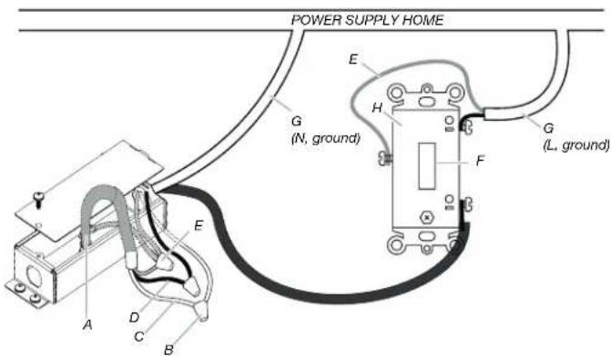
Electrical Connection

WARNING
ELECTRICAL SHOCK HAZARD.
DISCONNECT POWER BEFORE SERVICING. REPLACE ALL PARTS AND PANELS BEFORE OPERATING. FAILURE TO DO SO CAN RESULT IN DEATH OR ELECTRICAL SHOCK.
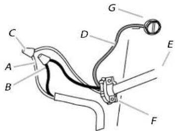
A. White wires
B. Black wires
C. UL listed wire connector
D. Green (or bare) ground wire
E. Homepower supply cable
F. UL listed or CSA approved ^1/2 " strain relief
G. Green ground screw
- Run 3 wires - black, white, and green - according to the National Electrical Code and local codes and ordinances, in 12 " conduit from the service panel to the junction box.

WARNING
ELECTRICALLY GROUND THE BLOWER. CONNECT THE GROUND WIRE TO THE GREEN AND YELLOW GROUND WIRES IN THE TERMINAL BOX. FAILURE TO DO SO CAN RESULT IN DEATH OR ELECTRICAL SHOCK.
- Connect the black wire from the service panel to the black or the red in the junction box. Connect the white to white and green to green-yellow.
- Close and secure the junction box cover with the screw previously removed.
Completing the Installation
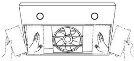
- Place the lateral panels by sliding them horizontally from the back of the hood and then secure the brackets on the front.
natural_image
Line drawing of two hands opening a fan into a rectangular box (no text or symbols)-
Place the filters and check the operation of the hood.
-
For vented installations: Install only the metal grease filter.
- For non-vented (recirculating) installations: Install both a charcoal and metal grease filter.
If the range hood does not operate:
- Confirm that the circuit breaker is not tripped or the house fuse blown.
- Disconnect the power supply, and then check if the wiring is correct.
- To get the most efficient use from your new range hood, read the "Range Hood Use and Care" section.
- Keep these Installation Instructions Guide close to range hood for easy reference.
Range Hood Description
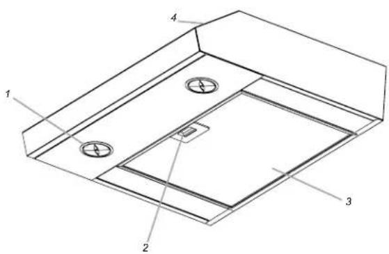
- LED lamps
- Filter handle
- Filter
- Control
Range Hood Controls

A. Light Power
B. Blower Off button
Operating the light
- The Light On/Off button (A) controls both lights. Press once for ON and again for OFF.
Operating the blower
- To turn the blower On press the blower button (B). Press the blower button again to turn the blower off.
Cleaning
Exterior surfaces:
To avoid damage to the exterior surface, do not use steel wool or soap-filled scouring pads. Do not use chlorine based cleaners. Rub in the direction of the grain line to avoid scratching the surface.
- For a thorough cleaning, use Stainless Steel Cleaner and Polish.
- For everyday cleaning, use a mild liquid detergent and water. Dry thoroughly.
- For a quick cleaning, wipe with a damp soft cloth or nonabrasive sponge, then rinse with clean water and wipe dry.
NOTE
Always wipe dry to avoid water marks.
Metal Grease Filter
For vented installations:
- Wash the metal filter as needed in a dishwasher or hot detergent solution.
- If needed replace the metal grease filter.
- When washed in a dishwasher, the grease filter may discolor slightly, but this does not affect its filtering capacity.
To replace metal grease filter:
- Remove the filter by pulling the latch toward the back of the range hood and using a Torx T10 adapter, remove the screw from the filter retainer, replace the filter and place the screw back.
natural_image
Technical diagram showing a mechanical assembly with two circular components and a dashed line indicating a step, no text or symbols present.Charcoal Filter
For non-vented (recirculating) installations:
The charcoal filter is not washable. It should last up to 6 months with normal use. Dispose of old charcoal filter.
To replace charcoal filter:
- Remove the metal grease filter from the range hood. See "Metal Grease Filter" in this section.
- Bend the spring clips away from the metal grease filter.
natural_image
Pure diagram of a rectangular plate with curved arrows indicating rotation or movement, no text or symbols present.- Replace the charcoal filter into the top side of metal filter.
- Insert the metal grease filter back into the range hood.
- Place again the screw from the filter retainer.
Charcoal filter is not included in the product, so please purchase it through the service center below if necessary. (Code Number: DG81-03610A)
Please contact SAMSUNG at:
www.samsung.com/ca/support (English)
www.samsung.com/ca_fr/support (French)
www.samsung.com/us/support (English)
Replacing the LED Lamp
LED lights are replaceable by a service technician only.
Range Hood for ADA Compliance
Range hoods can be installed to comply with Sections 308 and 309 of ADA Guidelines, when used with appropriately mounted controls installed at 15" (38.1 cm) to 40" (101.6 cm) above the floor and control access does not require reaching over a cooking appliance.
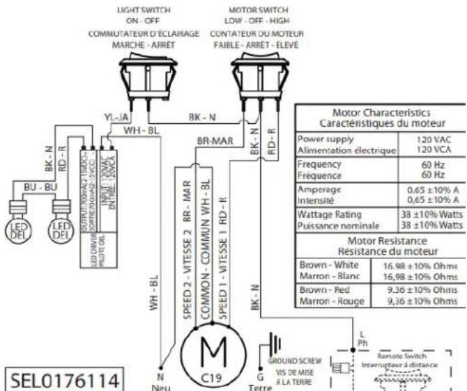
This range hood model NK30B3000US/AA can work in an ADA Compliant situation when the range hood is wired to operate from a dedicated, standard electrical wall switch. To facilitate this application, share the information on the following pages with your electrician when preparing for the installation.

NOTE
All the models can be controlled by only one remote switch (The switch activates or deactivates the motor and the light of the hood).

WARNING
All electrical work must be done in accordance with local codes, ordinances, or the national electrical code as applicable. For safety, this product must be installed in a grounded switch box. The electrical wiring installation must be done by a qualified technician.

WARNING
Electrical Shock Hazard
Turn off power at the circuit breaker panel or fuse box before servicing. Replace all parts and panels before operating.
Failure to do so can result in death or electrical shock.
A. Range Hood Cable
B. UL listed wire connector
C. White wires (N)
D. Black wires (L)
E. Green (or bare) and yellow-green ground
F. UL listed switch
G. Home power supply cable
H. Deep single gang switch box

WARNING
To avoid fire or electrical shock, turn off power at the circuit breaker panel or fuse box. Confirm that the power is off before wiring.
- MOUNT THE SWITCH BOX . Install a 3½" deepsingle gang switch box
- ATTACH THE POWER CABLE. Clamp wiring to the switch box and unit using an appropriate clamp. Provide 6" leads inside the box and fan for easier wiring.
-
CONNECT THE WIRING. General instructions:
-
Make sure both the switch box and the appliance are properly grounded.
- Make sure the ground wire is securely fastened to the control's ground screw. Tighten the ground screw.
- Use proper wire nut sizes for the number and size of the wires.
- For push-in and screw terminals: Use min. #14 AWG solid copper wire only.
- Tighten the screw terminals.
- Make electrical connections following the appropriate diagram.
- MOUNT THE CONTROL IN THE SWITCH BOX. Tuck wires into the switch box and fasten the control to the box using the attached screws.
- ATTACH THE SWITCH PLATE. Fasten the switch plate to the control using the short screws from the parts bag.
SAMSUNG RANGE HOOD
Limited warranty to original purchaser
This SAMSUNG brand product, as supplied and distributed by Samsung Electronics America, Inc. (SAMSUNG) and delivered new, in the original carton to the original consumer, is warranted by SAMSUNG against manufacturing defects in materials and workmanship for a limited warranty period starting on the date of delivery to the original consumer, of:
ONE (1) YEAR PARTS AND LABOR
This limited warranty begins on the original date of purchase, and is valid only on products purchased and used in the United States. To receive warranty service, the consumer must contact SAMSUNG for problem determination and service procedures. Warranty service can only be performed by a SAMSUNG authorized service center. The original dated bill of sale and/or proof of delivery must be presented upon request as proof of purchase to SAMSUNG or SAMSUNG's authorized service center.
SAMSUNG will repair or replace this product, at our option and at no charge as stipulated herein, with new or reconditioned parts or products if found to be defective during the limited warranty period specified above. All replaced parts and products become the property of SAMSUNG and must be returned to SAMSUNG. Replacement parts and products assume the remaining original warranty, or ninety (90) days, whichever is longer.
In-home service will be provided during the warranty labor period subject to availability within the contiguous United States. In-home service is not available in all areas. To receive in-home service, the product must be unobstructed and accessible to service personnel. If during in-home service repair can not be completed, it may be necessary to remove, repair and return the product.
This limited warranty covers manufacturing defects in materials and workmanship encountered in normal, noncommercial use of this product and shall not apply to the following, including, but not limited to: damage which occurs in shipment; delivery and installation; applications and uses for which this product was not intended; altered product or serial numbers; cosmetic damage or exterior finish; accidents, abuse, neglect, fire, water, lightning or other acts of nature; use of products, equipment, systems, utilities, services, parts, supplies, accessories, applications, installations, repairs, external wiring or connectors not supplied or authorized by SAMSUNG which damage this product or result in service problems; incorrect electrical line voltage, fluctuations and surges; customer adjustments and failure to follow operating instructions, cleaning, maintenance and environmental instructions that are covered and prescribed in the instruction book; problems caused by pest infestations, and overheating by user.
THERE ARE NO EXPRESS WARRANTIES OTHER THAN THOSE LISTED AND DESCRIBED ABOVE, AND NO WARRANTIES WHETHER EXPRESS OR IMPLIED, INCLUDING, BUT NOT LIMITED TO, ANY IMPLIED WARRANTIES OF MERCHANTABILITY OR FITNESS FOR A PARTICULAR PURPOSE, SHALL APPLY AFTER THE EXPRESS WARRANTY PERIODS STATED ABOVE, AND NO OTHER EXPRESS WARRANTY OR GUARANTY GIVEN BY ANY PERSON, FIRM OR CORPORATION WITH RESPECT TO THIS PRODUCT SHALL BE BINDING ON SAMSUNG. SAMSUNG SHALL NOT BE LIABLE FOR LOSS OF REVENUE OR PROFITS, FAILURE TO REALIZE SAVINGS OR OTHER BENEFITS, OR ANY OTHER SPECIAL, INCIDENTAL OR CONSEQUENTIAL DAMAGES CAUSED BY THE USE, MISUSE OR INABILITY TO USE THIS PRODUCT, REGARDLESS OF THE LEGAL THEORY ON WHICH THE CLAIM IS BASED, AND EVEN IF SAMSUNG HAS BEEN ADVISED OF THE POSSIBILITY OF SUCH DAMAGES. NOR SHALL RECOVERY OF ANY KIND AGAINST SAMSUNG BE GREATER IN AMOUNT THAN THE PURCHASE PRICE OF THE PRODUCT SOLD BY SAMSUNG AND CAUSING THE ALLEGED DAMAGE. WITHOUT LIMITING THE FOREGOING, PURCHASER ASSUMES ALL RISK AND LIABILITY FOR LOSS, DAMAGE OR INJURY TO PURCHASER AND PURCHASER'S PROPERTY AND TO OTHERS AND THEIR PROPERTY ARISING OUT OF THE USE, MISUSE OR INABILITY TO USE THIS PRODUCT SOLD BY SAMSUNG NOT CAUSED DIRECTLY BY THE NEGLIGENCE OF SAMSUNG. THIS LIMITED WARRANTY SHALL NOT EXTEND TO ANYONE OTHER THAN THE ORIGINAL PURCHASER OF THIS PRODUCT IS NONTRANSFERABLE AND STATES YOUR EXCLUSIVE REMEDY.
Some provinces or territories may or may not allow limitations on how long an implied warranty lasts, or the exclusion or limitation of incidental or consequential damages, so the above limitations or exclusions may not apply to you. This warranty gives you specific legal rights, and you may also have other rights which vary from state to state.
To obtain warranty service, please contact SAMSUNG at:
1-800-SAMSUNG (726-7864) or www.samsung.com/us/support
SAMSUNG RANGE HOOD
Limited warranty to original purchaser
This SAMSUNG brand product, as supplied and distributed by Samsung Electronics Canada, Inc. (SAMSUNG) and delivered new, in the original carton to the original consumer, is warranted by SAMSUNG against manufacturing defects in materials and workmanship for a limited warranty period starting on the date of delivery to the original consumer, of:
ONE (1) YEAR PARTS AND LABOR
This limited warranty begins on the original date of purchase, and is valid only on products purchased and used in Canada. To receive warranty service, the consumer must contact SAMSUNG for problem determination and service procedures. Warranty service can only be performed by a SAMSUNG authorized service center. The original dated bill of sale and/or proof of delivery must be presented upon request as proof of purchase to SAMSUNG or SAMSUNG's authorized service center.
SAMSUNG will repair or replace this product, at our option and at no charge as stipulated herein, with new or reconditioned parts or products if found to be defective during the limited warranty period specified above. All replaced parts and products become the property of SAMSUNG and must be returned to SAMSUNG. Replacement parts and products assume the remaining original warranty, or ninety (90) days, whichever is longer.
In-home service will be provided during the warranty labor period subject to availability within the contiguous Canada. In-home service is not available in all areas. To receive in-home service, the product must be unobstructed and accessible to service personnel. If during in-home service repair can not be completed, it may be necessary to remove, repair and return the product.
This limited warranty covers manufacturing defects in materials and workmanship encountered in normal, noncommercial use of this product and shall not apply to the following, including, but not limited to: damage which occurs in shipment; delivery and installation; applications and uses for which this product was not intended; altered product or serial numbers; cosmetic damage or exterior finish; accidents, abuse, neglect, fire, water, lightning or other acts of nature; use of products, equipment, systems, utilities, services, parts, supplies, accessories, applications,
installations, repairs, external wiring or connectors not supplied or authorized by SAMSUNG which damage this product or result in service problems; incorrect electrical line voltage, fluctuations and surges; customer adjustments and failure to follow operating instructions, cleaning, maintenance and environmental instructions that are covered and prescribed in the instruction book; problems caused by pest infestations, and overheating by user. SAMSUNG does not warrant uninterrupted or error-free operation of the product.
THERE ARE NO EXPRESS WARRANTIES OTHER THAN THOSE LISTED AND DESCRIBED ABOVE, AND NO WARRANTIES WHETHER EXPRESS OR IMPLIED, INCLUDING, BUT NOT LIMITED TO, ANY IMPLIED WARRANTIES OF MERCHANTABILITY OR FITNESS FOR A PARTICULAR PURPOSE, SHALL APPLY AFTER THE EXPRESS WARRANTY PERIODS STATED ABOVE, AND NO OTHER EXPRESS WARRANTY OR GUARANTY GIVEN BY ANY PERSON, FIRM OR CORPORATION WITH RESPECT TO THIS PRODUCT SHALL BE BINDING ON SAMSUNG. SAMSUNG SHALL NOT BE LIABLE FOR LOSS OF REVENUE OR PROFITS, FAILURE TO REALIZE SAVINGS OR OTHER BENEFITS, OR ANY OTHER SPECIAL, INCIDENTAL OR CONSEQUENTIAL DAMAGES CAUSED BY THE USE, MISUSE OR INABILITY TO USE THIS PRODUCT, REGARDLESS OF THE LEGAL THEORY ON WHICH THE CLAIM IS BASED, AND EVEN IF SAMSUNG HAS BEEN ADVISED OF THE POSSIBILITY OF SUCH DAMAGES. NOR SHALL RECOVERY OF ANY KIND AGAINST SAMSUNG BE GREATER IN AMOUNT THAN THE PURCHASE PRICE OF THE PRODUCT SOLD BY SAMSUNG AND CAUSING THE ALLEGED DAMAGE. WITHOUT LIMITING THE FOREGOING, PURCHASER ASSUMES ALL RISK AND LIABILITY FOR LOSS, DAMAGE OR INJURY TO PURCHASER AND PURCHASER'S PROPERTY AND TO OTHERS AND THEIR PROPERTY ARISING OUT OF THE USE, MISUSE OR INABILITY TO USE THIS PRODUCT SOLD BY SAMSUNG NOT CAUSED DIRECTLY BY THE NEGLIGENCE OF SAMSUNG. THIS LIMITED WARRANTY SHALL NOT EXTEND TO ANYONE OTHER THAN THE ORIGINAL PURCHASER OF THIS PRODUCT IS NONTRANSFERABLE AND STATES YOUR EXCLUSIVE REMEDY.
Some provinces or territories may or may not allow limitations on how long an implied warranty lasts, or the exclusion or limitation of incidental or consequential damages, so the above limitations or exclusions may not apply to you. This warranty gives you specific legal rights, and you may also have other rights which vary from state to state.
To obtain warranty service, please contact SAMSUNG at:
1-800-SAMSUNG (726-7864) or www.samsung.com/ca/support (English), www.samsung.com/ca_fr/support (French)
Sommaire
National Fire Protection Association
1 Batterymarch Park
Quincy, MA 02169-7471
CSA International
8501 East Pleasant Valley Road
Cleveland, OH 44131-5575
• Phillips (cruciforme) No. 2
- De lame plate
Pièces nécessaires
| NK30B3000US/AA | |
| A 30" (76 cm) | |
| B 18 | 34" (47,5 cm) |
| C 5" (12,5 cm) | |
| D 14 12" (36,7 cm) | |
| E 2" (5 cm) | |
| F 27 | ^15/_16" (70,9 cm) |
| G 9" (22,9 cm) | |
| H | 112" (3,8 cm) |
| I | 1" (2,5 cm) |
| J | 1815" (46 cm) |
natural_image
Simple line drawing of a mechanical component with a downward arrow and a rectangular base (no text or symbols)natural_image
Diagram of hands operating a fan inside a cabinet with directional arrows indicating airflow or movement (no text or symbols)Installation de la Hotte
natural_image
Technical line drawing of a rectangular metal enclosure with mounting holes and a labeled point B (no text or symbols beyond label)Préparer la hotte
natural_image
Technical line drawing of a mechanical assembly with no visible text or symbolsnatural_image
Technical line drawing of a fan assembly with mounting holes and a magnified inset showing internal components (no text or symbols)natural_image
Technical line drawing of a structural frame with a dashed dimension line and label 'A' (no text or symbols beyond label)A. Centerline
A. 8 2/5" (21.3cm)
natural_image
Line drawing of two hands opening a fan into a box (no text or symbols)natural_image
Technical diagram showing a mechanical assembly with mounting holes and a base plate, no text or symbols present.Filtre à Charbon
natural_image
Pure diagram of a rectangular plate with curved arrows indicating rotation or movement, no text or symbols present.www.samsung.com/ca/support (English)
www.samsung.com/ca_fr/support (French)
www.samsung.com/us/support (English)
Remplacement de la lampe LED
National Fire Protection Association
1 Batterymarch Park
Quincy, MA 02169-7471
CSA International
8501 East Pleasant Valley Road
Cleveland, OH 44131-5575
NK30B3000US/AA
| A 30" (76 cm) | |
| B 18 | 34" (47.5 cm) |
| C 5" (12.5 cm) | |
| D 14 12" (36.7 cm) | |
| E | 2" (5 cm) |
| F | 27^15/_16" (70.9 cm) |
| G 9" (22.9 cm) | |
| H | 112" (3.8 cm) |
| I | 1" (2.5 cm) |
| J | 1816" (46 cm) |
natural_image
Pure technical diagram showing a mechanical component with an arrow pointing to a rectangular feature (no text or symbols)natural_image
Diagram of hands holding a fan inside a device, showing directional arrows (no text or symbols)natural_image
Technical line drawing of a rectangular metal bracket with mounting holes and labeled point B (no text or symbols beyond label)natural_image
Technical line drawing of a mechanical assembly with internal components and a directional arrow (no text or symbols)natural_image
Technical line drawing of an air fan assembly with a magnified inset showing internal components (no text or symbols)natural_image
Pure architectural line drawing of a structural beam or support frame with no text, numbers, or symbolsA. Línea Central
A. 8 2/5" (21.3cm)
natural_image
Line drawing of two hands holding a fan inside a rectangular device (no text or symbols)- Lámparas LED
- Manijas de filtro de grasa
- Filtro
- Control
Controles de la Campana
natural_image
Technical diagram showing a mechanical assembly with a component inserted into a housing, before and after assembly (no text or symbols present)Filtro de carbón
natural_image
Pure diagram of a rectangular plate with curved arrows indicating rotation or force direction (no text or symbols)www.samsung.com/ca/support (English)
www.samsung.com/ca_fr/support (French)
www.samsung.com/us/support (English)
C. Cables blancos (N)


- Important Safety Instructions 3
- Installation Requirements 5
- Installation Instructions 7
- Range Hood Use and Care 11
- warranty (USA) 13
- warranty (Canada) 14
- APPROVED FOR RESIDENTIAL APPLIANCES
- READ AND SAVE THESE INSTRUCTIONS
- PLEASE READ ENTIRE INSTALLATION GUIDE BEFORE PROCEEDING. INSTALLATION MUST COMPLY WITH ALL LOCAL CODES.
- Symbols used in this manual
- WARNING
- CAUTION
- NOTE
- FCC Notice
- FCC STATEMENT:
- FCC RADIATION EXPOSURE STATEMENT:
- IC Notice
- IC RADIATION EXPOSURE STATEMENT:
- Electrical Requirements IMPORTANT
- Venting Requirements (ducted models only)
- Venting Methods
- Mounting Height
- Horizontal discharge
- Cold Weather Installations
- Makeup Air
- Installation Requirements
- Tools and Parts
- Parts supplied
- Tools/Materials required
- Parts needed
- For 7" (17.8 cm) round vented installations
- Installation Instructions
- Outside Top exhaust
- Prepare Range Hood
- Mark Hole Locations
- To wire through top:
- To wire through wall:
- Mark and Cut Vent Opening
- For 7" (17.8 cm) Round Vent System (Roof Venting)
- Drill Electrical Opening
- Prepare Range Hood Vents
- Install Strain Relief
- For non-vented (Recirculating) Installations
- 7" (17.8 cm) Round Vent Mounting Plate
- Mounting the Hood
- Connect Vent System
- Electrical Connection
- Completing the Installation
- Operating the light
- Operating the blower
- Cleaning
- Exterior surfaces:
- Metal Grease Filter
- For vented installations:
- Charcoal Filter
- For non-vented (recirculating) installations:
- Replacing the LED Lamp
- Range Hood for ADA Compliance
- SAMSUNG RANGE HOOD
- Limited warranty to original purchaser
- ONE (1) YEAR PARTS AND LABOR
- Sommaire
- Pièces nécessaires
- Installation de la Hotte
- Préparer la hotte
- Filtre à Charbon
- Remplacement de la lampe LED
- Filtro de carbón
Brand : SAMSUNG
Model : NK30B3000US
Category : Range hood