
B660M-ITX/eDP - Motherboard ASROCK - Free user manual and instructions
Find the device manual for free B660M-ITX/eDP ASROCK in PDF.

| Product Type | Motherboard |
| Brand | ASRock |
| Model | B660M-ITX/eDP |
| Form Factor | Mini-ITX (17.0 cm x 17.0 cm) |
| Processor Socket | LGA1700 (Intel Core 12th Gen) |
| Chipset | Intel B660 |
| Supported Memory | DDR4, 2 slots, max 64 GB, up to 5000+ (OC), XMP 2.0 |
| Expansion Slots | 1 x PCIe 4.0 x16, 1 x M.2 vertical (CNVi/BT) |
| Graphics Outputs | eDP 1.4, HDMI 2.1 (TMDS), DisplayPort 1.4 (triple monitor) |
| Audio | Realtek ALC897, 7.1 HD channels, surge protection |
| Network | Gigabit LAN Intel I219V, Wi-Fi 802.11ac + Bluetooth 5.1 |
| Storage | 1 x Ultra M.2 (PCIe Gen3 x4 or SATA3), 4 x SATA3 6 Gb/s, RAID 0/1/5/10 |
| Internal Connectors | eDP, USB 3.2 Gen1, USB 2.0, fans (CPU, chassis, pump), ATX 24-pin, ATX 12V 8-pin, front panel audio |
| BIOS | UEFI AMI with multilingual GUI |
| Operating System | Windows 10 64-bit / Windows 11 64-bit |
| Certifications | FCC, CE, ErP/EuP Ready |
| Security | ESD protection on USB, lightning/ESD protection on LAN, audio surge protection |
Frequently Asked Questions - B660M-ITX/eDP ASROCK
User questions about B660M-ITX/eDP ASROCK
0 question about this device. Answer the ones you know or ask your own.
Ask a new question about this device
Download the instructions for your Motherboard in PDF format for free! Find your manual B660M-ITX/eDP - ASROCK and take your electronic device back in hand. On this page are published all the documents necessary for the use of your device. B660M-ITX/eDP by ASROCK.
USER MANUAL B660M-ITX/eDP ASROCK
Copyright©2022 ASRock INC. All rights reserved.
Copyright Notice:
No part of this documentation may be reproduced, transcribed, transmitted, or translated in any language, in any form or by any means, except duplication of documentation by the purchaser for backup purpose, without written consent of ASRock Inc.
Products and corporate names appearing in this documentation may or may not be registered trademarks or copyrights of their respective companies, and are used only for identification or explanation and to the owners' benefit, without intent to infringe.
Disclaimer:
Specifications and information contained in this documentation are furnished for informational use only and subject to change without notice, and should not be constructed as a commitment by ASRock. ASRock assumes no responsibility for any errors or omissions that may appear in this documentation.
With respect to the contents of this documentation, ASRock does not provide warranty of any kind, either expressed or implied, including but not limited to the implied warranties or conditions of merchantability or fitness for a particular purpose.
In no event shall ASRock, its directors, officers, employees, or agents be liable for any indirect, special, incidental, or consequential damages (including damages for loss of profits, loss of business, loss of data, interruption of business and the like), even if ASRock has been advised of the possibility of such damages arising from any defect or error in the documentation or product.

This device complies with Part 15 of the FCC Rules. Operation is subject to the following two conditions:
(1) this device may not cause harmful interference, and
(2) this device must accept any interference received, including interference that may cause undesired operation.
This equipment has been tested and found to comply with the limits for a Class B digital device, pursuant to part 15 of the FCC Rules. These limits are designed to provide reasonable protection against harmful interference in a residential installation. This equipment generates, uses and can radiate radio frequency energy and, if not installed and used in accordance with the instructions, may cause harmful interference to radio communications. However, there is no guarantee that interference will not occur in a particular installation. If this equipment does cause harmful interference to radio or television reception, which can be determined by turning the equipment off and on, the user is encouraged to try to correct the interference by one or more of the following measures:
- Reorient or relocate the receiving antenna.
- Increase the separation between the equipment and receiver.
- Connect the equipment into an outlet on a circuit different from that to which the receiver is connected.
- Consult the dealer or an experienced radio/TV technician for help.

The terms HDMI ^® and HDMI High-Definition Multimedia Interface, and the HDMI logo are trademarks or registered trademarks of HDMI Licensing LLC in the United States and other countries.

INTEL END USER SOFTWARE LICENSE AGREEMENT IMPORTANT - READ BEFORE COPYING, INSTALLING OR USING.
LICENSE. Licensee has a license under Intel's copyrights to reproduce Intel's Software only in its unmodified and binary form, (with the accompanying documentation, the "Software") for Licensee's personal use only, and not commercial use, in connection with Intel-based products for which the Software has been provided, subject to the following conditions:
(a) Licensee may not disclose, distribute or transfer any part of the Software, and You agree to prevent unauthorized copying of the Software.
(b) Licensee may not reverse engineer, decompile, or disassemble the Software.
(c) Licensee may not sublicense the Software.
(d) The Software may contain the software and other intellectual property of third party suppliers, some of which may be identified in, and licensed in accordance with, an enclosed license.txt file or other text or file.
(e) Intel has no obligation to provide any support, technical assistance or updates for the Software.
OWNERSHIP OF SOFTWARE AND COPYRIGHTS. Title to all copies of the Software remains with Intel or its licensors or suppliers. The Software is copyrighted and protected by the laws of the United States and other countries, and international treaty provisions. Licensee may not remove any copyright notices from the Software. Except as otherwise expressly provided above, Intel grants no express or implied right under Intel patents, copyrights, trademarks, or other intellectual property rights. Transfer of the license terminates Licensee's right to use the Software.
DISCLAIMER OF WARRANTY. The Software is provided “AS IS” without warranty of any kind, EITHER EXPRESS OR IMPLIED, INCLUDING WITHOUT LIMITATION, WARRANTIES OF MERCHANTABILITY OR FITNESS FOR ANY PARTICULAR PURPOSE.
LIMITATION OF LIABILITY. NEITHER INTEL NOR ITS LICENSORS OR SUPPLIERS WILL BE LIABLE FOR ANY LOSS OF PROFITS, LOSS OF USE, INTERRUPTION OF BUSINESS, OR INDIRECT, SPECIAL, INCIDENTAL, OR CONSEQUENTIAL DAMAGES OF ANY KIND WHETHER UNDER THIS AGREEMENT OR OTHERWISE, EVEN IF INTEL HAS BEEN ADVISED OF THE POSSIBILITY OF SUCH DAMAGES.
LICENSE TO USE COMMENTS AND SUGGESTIONS. This Agreement does NOT obligate Licensee to provide Intel with comments or suggestions regarding the Software. However, if Licensee provides Intel with comments or suggestions for the modification, correction, improvement or enhancement of (a) the Software or (b) Intel products or processes that work with the Software, Licensee grants to Intel a non-exclusive, worldwide, perpetual, irrevocable, transferable, royalty-free license, with the right to sublicense, under
Licensee's intellectual property rights, to incorporate or otherwise utilize those comments and suggestions.
TERMINATION OF THIS LICENSE. Intel or the sublicensor may terminate this license at any time if Licensee is in breach of any of its terms or conditions. Upon termination, Licensee will immediately destroy or return to Intel all copies of the Software.
THIRD PARTY BENEFICIARY. Intel is an intended beneficiary of the End User License Agreement and has the right to enforce all of its terms.
U.S. GOVERNMENT RESTRICTED RIGHTS. The Software is a commercial item (as defined in 48 C.F.R. 2.101) consisting of commercial computer software and commercial computer software documentation (as those terms are used in 48 C.F.R. 12.212), consistent with 48 C.F.R. 12.212 and 48 C.F.R 227.7202-1 through 227.7202-4. You will not provide the Software to the U.S. Government. Contractor or Manufacturer is Intel Corporation, 2200 Mission College Blvd., Santa Clara, CA 95054.
EXPORT LAWS. Licensee agrees that neither Licensee nor Licensee's subsidiaries will export/re-export the Software, directly or indirectly, to any country for which the U.S. Department of Commerce or any other agency or department of the U.S. Government or the foreign government from where it is shipping requires an export license, or other governmental approval, without first obtaining any such required license or approval. In the event the Software is exported from the U.S.A. or re-exported from a foreign destination by Licensee, Licensee will ensure that the distribution and export/re-export or import of the Software complies with all laws, regulations, orders, or other restrictions of the U.S. Export Administration Regulations and the appropriate foreign government.
APPLICABLE LAWS. This Agreement and any dispute arising out of or relating to it will be governed by the laws of the U.S.A. and Delaware, without regard to conflict of laws principles. The Parties to this Agreement exclude the application of the United Nations Convention on Contracts for the International Sale of Goods (1980). The state and federal courts sitting in Delaware, U.S.A. will have exclusive jurisdiction over any dispute arising out of or relating to this Agreement. The Parties consent to personal jurisdiction and venue in those courts. A Party that obtains a judgment against the other Party in the courts identified in this section may enforce that judgment in any court that has jurisdiction over the Parties.
Licensee's specific rights may vary from country to country.
CALIFORNIA, USA ONLY
The Lithium battery adopted on this motherboard contains Perchlorate, a toxic substance controlled in Perchlorate Best Management Practices (BMP) regulations passed by the California Legislature. When you discard the Lithium battery in California, USA, please follow the related regulations in advance.
"Perchlorate Material-special handling may apply, see www.dtsc.ca.gov/hazardouswaste/perchlorate"
AUSTRALIA ONLY
Our goods come with guarantees that cannot be excluded under the Australian Consumer Law. You are entitled to a replacement or refund for a major failure and compensation for any other reasonably foreseeable loss or damage caused by our goods. You are also entitled to have the goods repaired or replaced if the goods fail to be of acceptable quality and the failure does not amount to a major failure. If you require assistance please call ASRock Tel: +886-2-28965588 ext.123 (Standard International call charges apply)
UK CA
ASRock INC. hereby declares that this device is in compliance with the essential requirements and other relevant provisions of related UKCA Directives. Full text of UKCA declaration of conformity is available at: http://www.asrock.com
CE
ASRock INC. hereby declares that this device is in compliance with the essential requirements and other relevant provisions of related Directives. Full text of EU declaration of conformity is available at: http://www.asrock.com
ASRock follows the green design concept to design and manufacture our products, and makes sure that each stage of the product life cycle of ASRock product is in line with global environmental regulations. In addition, ASRock disclose the relevant information based on regulation requirements.
Please refer to https://www.asrock.com/general/about.asp?cat=Responsibility for information disclosure based on regulation requirements ASRock is complied with:

DO NOT throw the motherboard in municipal waste. This product has been designed to enable proper reuse of parts and recycling. This symbol of the crossed out wheeled bin indicates that the product (electrical and electronic equipment) should not be placed in municipal waste. Check local regulations for disposal of electronic products.
CE Warning
This device complies with directive 2014/53/EU issued by the Commission of the European Community.
This equipment complies with EU radiation exposure limits set forth for an uncontrolled environment.
This equipment should be installed and operated with minimum distance 20cm between the radiator & your body.
Operations in the 5.15-5.35GHz band are restricted to indoor usage only.
| AT | BE | BG | CH | CY | CZ | DE | |
| DK | EE | EL | ES | FI | FR | HR | |
| HU | IE | IS | IT | LI | LT | LU | |
| LV | MT | NL | NO | PL | PT | RO | |
| SE | SI | SK | TR |

Radio transmit power per transceiver type
Function Frequency Maximum Output Power (EIRP)
| 2400-2483.5 MHz 18.5 + / -1.5 dbm | ||
| 5150-5250 MHz 21.5 + / -1.5 dbm | ||
| WiFi | 5250-5350 MHz | 18.5 + / -1.5 dbm (no TPC) |
| 21.5 + / -1.5 dbm (TPC) | ||
| 5470-5725 MHz | 25.5 + / -1.5 dbm (no TPC) | |
| 28.5 + / -1.5 dbm (TPC) | ||
Bluetooth 2400-2483.5 MHz 8.5 + / -1.5 dbm
ASRock Incorporation
Contains Wi-Fi module with Bluetooth
Intel® Wi-Fi 9462
Model: 9462NGW
FCC ID: PD99462NG
IC:1000M-9462NG


R 003-170245
T D170151003

CCAH17LP4350T0
5.15\~5.35GHz indoor use only
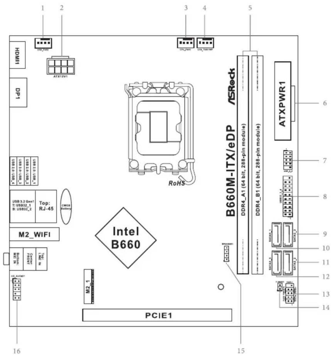
Motherboard Layout
Top Side View
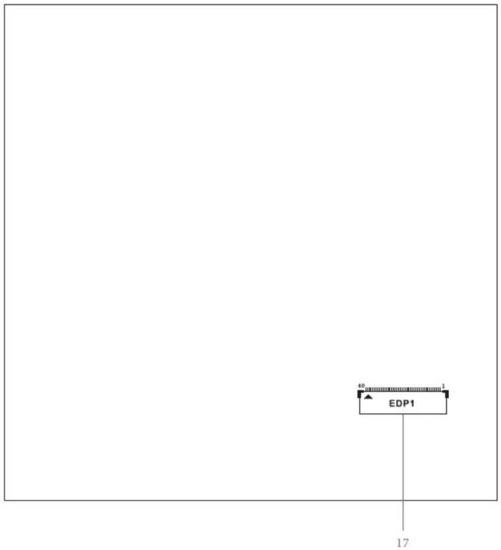
Back Side View
No. Description
1 Chassis Fan Connector (CHA_FAN2)
2 ATX 12V Power Connector (ATX12V1)
3 CPU Fan Connector (CPU_FAN1)
4 Chassis/Water Pump Fan Connector (CHA_FAN1/WP)
5 2 x 288-pin DDR4 DIMM Slots (DDR4_A1, DDR4_B1)
6 ATX Power Connector (ATXPWR1)
7 USB 2.0 Header (USB_5_6)
8 USB 3.2 Gen1 Header (USB32_3_4)
9 SATA3 Connector (SATA3_0)
10 SATA3 Connector (SATA3_1)
11 SATA3 Connector (SATA3_2)
12 SATA3 Connector (SATA3_3)
13 System Panel Header (PANEL1)
14 Clear CMOS Jumper (CLRMOS1)
15 Chassis Speaker Header (SPEAKER1)
16 Front Panel Audio Header (HD_AUDIO1)
17 eDP Signal Connector (EDP1)
I/O Panel
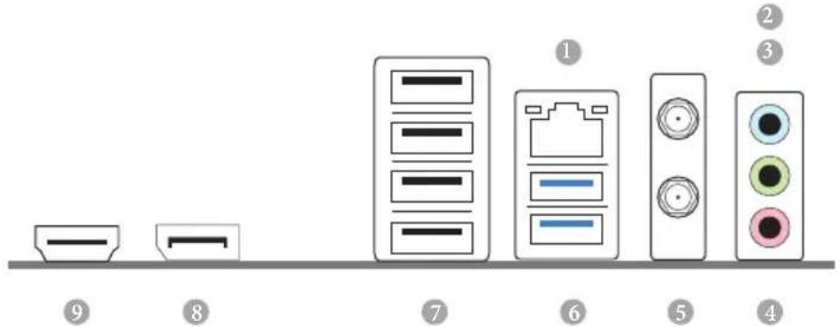
No. Description No. Description
1 LAN RJ-45 Port* 6 USB 3.2 Gen1 Ports (USB32_12)
2 Line In (Light Blue)** 7 USB 2.0 Ports (USB_1234)***
3 Front Speaker (Lime) ^ 8 DisplayPort 1.4
4 Microphone (Pink) ^ 9 HDMI Port
5 Antenna Ports
* There are two LEDs on each LAN port. Please refer to the table below for the LAN port LED indications.
ACT/LINK LED
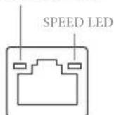
LAN Port
Activity / Link LED Speed LED
Status Description Status Description
| Off No Link Off | 10Mbps connection | ||
| Blinking | Data Activity Orange | 100Mbps connection | |
| On Link | Green | 1Gbps connection | |
** Function of the Audio Ports in 7.1-channel Configuration:
| Port | Function |
| Light Blue (Rear panel) | Rear Speaker Out |
| Lime (Rear panel) | Front Speaker Out |
| Pink (Rear panel) | Central /Subwoofer Speaker Out |
| Lime (Front panel) | Side Speaker Out |
*** CNVi BT shares bandwidth with the top USB 2.0 port (USB_1). When CNVi BT is used, USB_1 becomes unavailable.
WiFi-802.11ac Module and ASRock WiFi 2.4/5 GHz Antennas
WiFi-802.11ac + BT Module
This motherboard comes with an exclusive WiFi 802.11 a/b/g/n/ac + BT v5.1 module (pre-installed on the rear I/O panel) that offers support for WiFi 802.11 a/b/g/n/ac connectivity standards and Bluetooth v5.1. WiFi + BT module is an easy-to-use wireless local area network (WLAN) adapter to support WiFi + BT. Bluetooth v5.1 standard features Smart Ready technology that adds a whole new class of functionality into the mobile devices. BT 5.1 also includes Low Energy Technology and ensures extraordinary low power consumption for PCs.
* The transmission speed may vary according to the environment.
* CNVi BT shares bandwidth with the top USB 2.0 port (USB_1) on the rear I/O. When CNVi BT is used, USB_1 becomes unavailable.
WiFi Antennas Installation Guide
natural_image
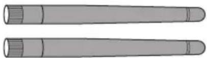
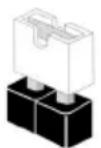
Two identical cylindrical objects with segmented ends, no text or symbols visibleStep 1
Prepare the WiFi 2.4/5 GHz Antennas that come with the package.
natural_image
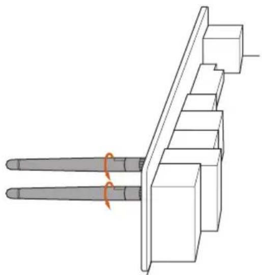
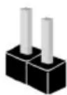
Technical line drawing of a mechanical assembly with two cylindrical components and a central bracket (no text or symbols)Step 2
Connect the two WiFi 2.4/5 GHz Antennas to the antenna connectors. Turn the antenna clockwise until it is securely connected.
natural_image
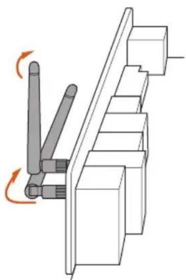
Mechanical assembly diagram showing a lever mechanism with rotating arrows (no text or symbols)Step 3
Set the WiFi 2.4/5 GHz Antenna as shown in the illustration.
*You may need to adjust the direction of the antenna for a stronger signal.
Chapter 1 Introduction
Thank you for purchasing ASRock B660M-ITX/eDP motherboard, a reliable motherboard produced under ASRock's consistently stringent quality control. It delivers excellent performance with robust design conforming to ASRock's commitment to quality and endurance.

Because the motherboard specifications and the BIOS software might be updated, the content of this documentation will be subject to change without notice. In case any modifications of this documentation occur, the updated version will be available on ASRock's website without further notice. If you require technical support related to this motherboard, please visit our website for specific information about the model you are using. You may find the latest VGA cards and CPU support list on ASRock's website as well. ASRock website http://www.asrock.com.
1.1 Package Contents
• ASRock B660M-ITX/eDP Motherboard (Mini-ITX Form Factor)
• ASRock B660M-ITX/eDP Quick Installation Guide
• ASRock B660M-ITX/eDP Support CD
• 2 x Serial ATA (SATA) Data Cables (Optional)
• 2 x ASRock WiFi 2.4/5 GHz Antennas (Optional)
• 1 x Screw for M.2 Socket (Optional)
• 1 x I/O Panel Shield
1.2 Specifications
| Platform | Mini-ITX Form FactorSolid Capacitor design |
| CPU | Supports 14^th , 13^th & 12^th Gen Intel® CoreTM Processors (LGA1700)Digi Power design6 Power Phase designSupports Intel® Hybrid TechnologySupports Intel® Turbo Boost Max 3.0 Technology |
| Chipset | Intel® B660 |
| Memory | Dual Channel DDR4 Memory Technology2 x DDR4 DIMM SlotsSupports DDR4 non-ECC, un-buffered memory up to 5000+(OC)*Supports DDR4 3200 natively.* Please refer to Memory Support List on ASRock's website for more information. (http://www.asrock.com/)Supports ECC UDIMM memory modules (operate in non-ECC mode)Max. capacity of system memory: 64GBSupports Intel® Extreme Memory Profile (XMP) 2.0 |
| Expansion Slot | CPU:1 x PCIe 4.0 x16 Slot (PCIE1), supports x16 mode*Chipset:1 x Vertical M.2 Socket (Key E), supports type 2230 Intel® CNVi (Integrated WiFi/BT)**Supports NVMe SSD as boot disks** CNVi BT shares bandwidth with the top USB 2.0 port (USB_1) on the rear I/O. When CNVi BT is used, USB_1 becomes unavailable. |
| Graphics | Intel® UHD Graphics Built-in Visuals and the VGA outputs can be supported only with processors which are GPU integrated.Intel® Xe Graphics Architecture (Gen 12) |
- Three graphics output options: eDP 1.4, HDMI and DisplayPort 1.4
• Supports Triple Monitor - Supports eDP 1.4 with max. resolution up to Full HD (1920x1080) @ 60Hz
- Supports HDMI 2.1 TMDS Compatible with max. resolution up to 4K x 2K (4096x2160) @ 60Hz
- Supports DisplayPort 1.4 with DSC (compressed) max. resolution up to 8K (7680x4320) @ 60Hz / 5K (5120x3200) @ 120Hz
- Supports HDCP 2.3 with eDP 1.4, HDMI 2.1 TMDS Compatible and DisplayPort 1.4 Ports
Audio
• 7.1 CH HD Audio (Realtek ALC897 Audio Codec)
• Supports Surge Protection
LAN
• Gigabit LAN 10/100/1000 Mb/s
• Giga PHY Intel® I219V
• Supports Wake-On-LAN
• Supports Lightning/ESD Protection
• Supports Energy Efficient Ethernet 802.3az
• Supports UEFI PXE
Wireless
• 802.11ac WiFi Module
• Supports IEEE 802.11a/b/g/n/ac
• Supports Dual-Band (2.4/5 GHz)
• Supports high speed wireless connections up to 433Mbps
• Supports Bluetooth 5.1 + High speed class II
Rear Panel
- 2 x Antenna Ports
- 1 x HDMI Port
- 1 x DisplayPort 1.4
- 2 x USB 3.2 Gen1 Ports (Supports ESD Protection)
- 4 x USB 2.0 Ports (Supports ESD Protection)*
* CNVi BT shares bandwidth with the top USB 2.0 port (USB_1). When CNVi BT is used, USB_1 becomes unavailable.
- 1 x RJ-45 LAN Port with LED (ACT/LINK LED and SPEED LED)
• HD Audio Jacks: Line in / Front Speaker / Microphone
Storage
Chipset:
- 1 x Ultra M.2 Socket (M2_1, Key M), supports type 2280 SATA3 6.0 Gb/s & PCIe Gen3x4 (32 Gb/s) modes*
• 4 x SATA3 6.0 Gb/s Connectors**
* Supports Intel® Optane™ Technology
* Supports Intel® Volume Management Device (VMD)
* Supports NVMe SSD as boot disks
* Supports ASRock U.2 Kit
** If M2_1 is occupied by a SATA-type M.2 device, SATA3_0 will be disabled.
RAID
- Supports RAID 0, RAID 1, RAID 5 and RAID 10 for SATA storage devices
Connector
• 1 x eDP Signal Connector
• 1 x CPU Fan Connector (4-pin)
* The CPU Fan Connector supports the CPU fan of maximum 1A (12W) fan power.
• 1 x Chassis Fan Connector (4-pin)
* The Chassis Fan Connector supports the chassis fan of maximum 1A (12W) fan power.
- 1 x Chassis/Water Pump Fan Connector (4-pin) (Smart Fan Speed Control)
* The Chassis/Water Pump Fan supports the water cooler fan of maximum 2A (24W) fan power.
* CHA_FAN1/WP can auto detect if 3-pin or 4-pin fan is in use.
• 1 x 24 pin ATX Power Connector
• 1 x 8 pin 12V Power Connector
• 1 x Front Panel Audio Connector
- 1 x USB 2.0 Header (Supports 2 USB 2.0 ports) (Supports ESD Protection)
- 1 x USB 3.2 Gen1 Header (Supports 2 USB 3.2 Gen1 ports) (Supports ESD Protection)
BIOS
• AMI UEFI Legal BIOS with multilingual GUI support
Feature
• ACPI 6.0 Compliant wake up events
- SMBIOS 2.7 Support
- CPU Core/Cache, CPU GT, DRAM, VCCIN AUX, +1.05V PROC, +1.8V PROC, +0.82V PCH, +1.05V PCH Voltage Multi-adjustment
Hardware Monitor
• Fan Tachometer: CPU, Chassis, Chassis/Water Pump Fans
- Quiet Fan (Auto adjust chassis fan speed by CPU temperature): CPU, Chassis, Chassis/Water Pump Fans
- Fan Multi-Speed Control: CPU, Chassis, Chassis/Water Pump Fans
- Voltage monitoring: CPU Vcore, +12V, +5V, +3.3V, +1.05V PCH
os
- Microsoft® Windows® 10 64-bit / 11 64-bit
Certifications
- FCC, CE
- ErP/EuP ready (ErP/EuP ready power supply is required)
* For detailed product information, please visit our website: http://www.asrock.com

Please realize that there is a certain risk involved with overclocking, including adjusting the setting in the BIOS, applying Untied Overclocking Technology, or using third-party overclocking tools. Overclocking may affect your system's stability, or even cause damage to the components and devices of your system. It should be done at your own risk and expense. We are not responsible for possible damage caused by overclocking.
Chapter 2 Installation
This is a Mini-ITX form factor motherboard. Before you install the motherboard, study the configuration of your chassis to ensure that the motherboard fits into it.
Pre-installation Precautions
Take note of the following precautions before you install motherboard components or change any motherboard settings.
- Make sure to unplug the power cord before installing or removing the motherboard components. Failure to do so may cause physical injuries and damages to motherboard components.
- In order to avoid damage from static electricity to the motherboard's components, NEVER place your motherboard directly on a carpet. Also remember to use a grounded wrist strap or touch a safety grounded object before you handle the components.
- Hold components by the edges and do not touch the ICs.
- Whenever you uninstall any components, place them on a grounded anti-static pad or in the bag that comes with the components.
- When placing screws to secure the motherboard to the chassis, please do not over-tighten the screws! Doing so may damage the motherboard.
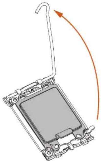
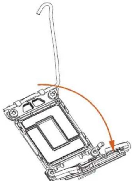
2.1 Installing the CPU

- Before you insert the 1700-Pin CPU into the socket, please check if the PnP cap is on the socket, if the CPU surface is unclean, or if there are any bent pins in the socket. Do not force to insert the CPU into the socket if above situation is found. Otherwise, the CPU will be seriously damaged.
- Unplug all power cables before installing the CPU.
1
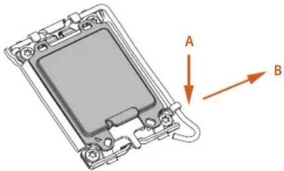
natural_image
3D diagram of a device casing with labeled arrows A and B indicating directional components (no text or symbols beyond labels)2
natural_image
Diagram of a mechanical component with an arrow indicating rotation or movement, no text or symbols present3
natural_image
Technical line drawing of a mechanical device with a curved handle and orange arrow indicating motion (no text or symbols)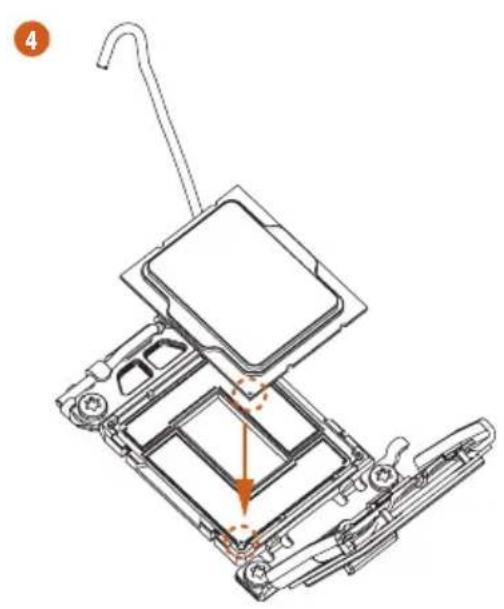
natural_image
Technical line drawing of a mechanical assembly with no visible text or symbols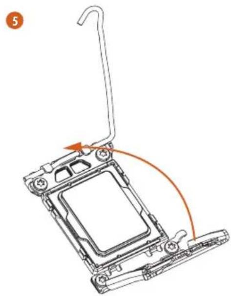
natural_image
Diagram of a mechanical device with a hook and orange curved arrow indicating motion (no text or symbols)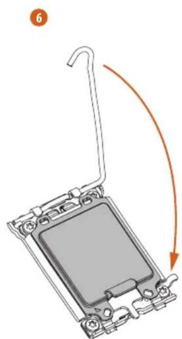
natural_image
Diagram of a mechanical component with an arrow indicating rotation or movement, no text or symbols present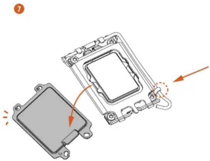
natural_image
Diagram of a computer processor showing internal components and a close-up view of the base (no text or symbols)
Please save and replace the cover if the processor is removed. The cover must be placed if you wish to return the motherboard for after service.
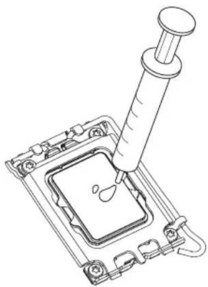
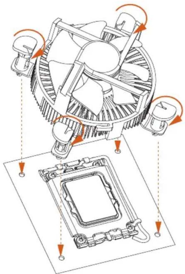
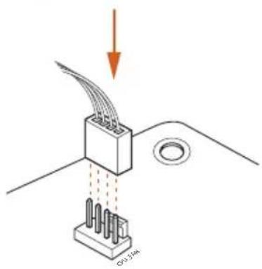
2.2 Installing the CPU Fan and Heatsink
natural_image
Technical line drawing of a pipette inserted into a microchip (no text or symbols)1
2
2.3 Installing Memory Modules (DIMM)
This motherboard provides two 288-pin DDR4 (Double Data Rate 4) DIMM slots, and supports Dual Channel Memory Technology.

- For dual channel configuration, you always need to install identical (the same brand, speed, size and chip-type) DDR4 DIMM pairs.
- It is unable to activate Dual Channel Memory Technology with only one memory module installed.
- It is not allowed to install a DDR, DDR2 or DDR3 memory module into a DDR4 slot; otherwise, this motherboard and DIMM may be damaged.

The DIMM only fits in one correct orientation. It will cause permanent damage to the motherboard and the DIMM if you force the DIMM into the slot at incorrect orientation.
1
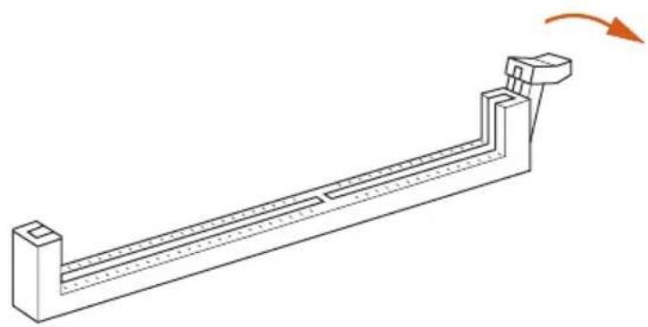
natural_image
Technical line drawing of a mechanical support structure with an orange arrow indicating rotation (no text or symbols)2
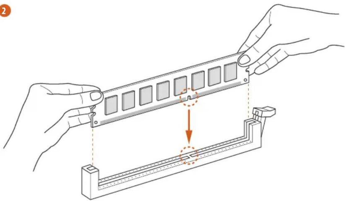
natural_image
Illustration of hands assembling a mechanical component with a highlighted section (no text or symbols)3
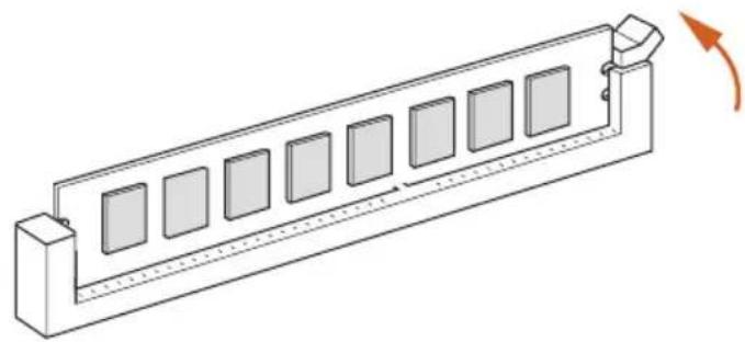
natural_image
Isometric line drawing of a rectangular device with multiple square panels and a curved arrow indicating rotation (no text or symbols)2.4 Expansion Slots (PCIe Slot)
There is 1 PCIe slot on the motherboard.

Before installing an expansion card, please make sure that the power supply is switched off or the power cord is unplugged. Please read the documentation of the expansion card and make necessary hardware settings for the card before you start the installation.
PCIe slots:
PCIE1 (PCIe 4.0 x16 slot) is used for PCIe x16 lane width graphics cards.
2.5 Jumpers Setup
The illustration shows how jumpers are setup. When the jumper cap is placed on the pins, the jumper is “Short”. If no jumper cap is placed on the pins, the jumper is “Open”.
Short
Open
Clear CMOS Jumper
(CLRMOS1)
(see p.1, No. 14)

2-pin Jumper
CLRMOS1 allows you to clear the data in CMOS. To clear and reset the system parameters to default setup, please turn off the computer and unplug the power cord from the power supply. After waiting for 15 seconds, use a jumper cap to short the pins on CLRMOS1 for 5 seconds. However, please do not clear the CMOS right after you update the BIOS. If you need to clear the CMOS when you just finish updating the BIOS, you must boot up the system first, and then shut it down before you do the clear-CMOS action. Please be noted that the password, date, time, and user default profile will be cleared only if the CMOS battery is removed. Please remember to remove the jumper cap after clearing the CMOS.
2.6 Onboard Headers and Connectors

Onboard headers and connectors are NOT jumpers. Do NOT place jumper caps over these headers and connectors. Placing jumper caps over the headers and connectors will cause permanent damage to the motherboard.
System Panel Header
(9-pin PANEL1)
(see p.1, No. 13)
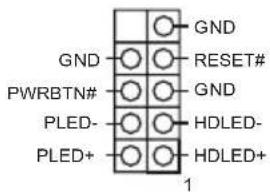
Connect the power button, reset button and system status indicator on the chassis to this header according to the pin assignments below. Note the positive and negative pins before connecting the cables.

PWRBTN (Power Button):
Connect to the power button on the chassis front panel. You may configure the way to turn off your system using the power button.
RESET (Reset Button):
Connect to the reset button on the chassis front panel. Press the reset button to restart the computer if the computer freezes and fails to perform a normal restart.
PLED (System Power LED):
Connect to the power status indicator on the chassis front panel. The LED is on when the system is operating. The LED keeps blinking when the system is in S1/S3 sleep state. The LED is off when the system is in S4 sleep state or powered off (S5).
HDLED (Hard Drive Activity LED):
Connect to the hard drive activity LED on the chassis front panel. The LED is on when the hard drive is reading or writing data.
The front panel design may differ by chassis. A front panel module mainly consists of power button, reset button, power LED, hard drive activity LED, speaker and etc. When connecting your chassis front panel module to this header, make sure the wire assignments and the pin assignments are matched correctly.
Serial ATA3 Connectors
(SATA3_0:
see p.1, No. 9)
(SATA3_1:
see p.1, No. 10)
(SATA3_2:
see p.1, No. 11)
(SATA3_3:
see p.1, No. 12)
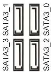
These four SATA3
connectors support SATA data cables for internal
storage devices with up to
6.0 Gb/s data transfer rate.
* If M2_1 is occupied by a SATA-type M.2 device,
SATA3_0 will be disabled.
USB 2.0 Header
(9-pin USB_5_6)
(see p.1, No. 7)
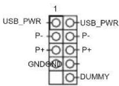
There is one USB
2.0 header on this motherboard. This USB
2.0 header can support two ports.
USB 3.2 Gen1 Header
(19-pin USB32_3_4)
(see p.1, No. 8)
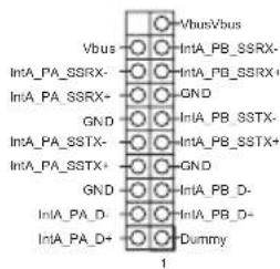
There is one header on this motherboard. This
USB 3.2 Gen1 header can support two ports.
Front Panel Audio Header
(9-pin HD_AUDIO1)
(see p.1, No. 16)
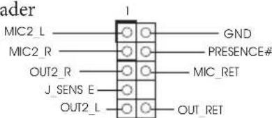
This header is for connecting audio devices to the front audio panel.

- High Definition Audio supports Jack Sensing, but the panel wire on the chassis must support HDA to function correctly. Please follow the instructions in our manual and chassis manual to install your system.
- If you use an AC'97 audio panel, please install it to the front panel audio header by the steps below:
A. Connect Mic_IN (MIC) to MIC2_L.
B. Connect Audio_R (RIN) to OUT2_R and Audio_L (LIN) to OUT2_L.
C. Connect Ground (GND) to Ground (GND).
D. MIC_RET and OUT_RET are for the HD audio panel only. You don't need to connect them for the AC'97 audio panel.
E. To activate the front mic, go to the "FrontMic" Tab in the Realtek Control panel and adjust "Recording Volume".
Chassis Speaker Header
(4-pin SPEAKER1)
(see p.1, No. 15)

Please connect the chassis speaker to this header.
Chassis/Water Pump Fan
Connector
(4-pin CHA_FAN1/WP)
(see p.1, No. 4)
This motherboard provides a 4-Pin water cooling chassis fan connector. If you plan to connect a 3-Pin chassis water cooler fan, please connect it to Pin 1-3.
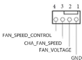
Chassis Fan Connector
(4-pin CHA_FAN2)
(see p.1, No. 1)
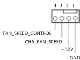
Please connect fan cables to the fan connector and match the black wire to the ground pin.
CPU Fan Connector
(4-pin CPU_FAN1)
(see p.1, No. 3)
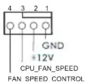
This motherboard provides a 4-Pin CPU fan (Quiet Fan) connector. If you plan to connect a 3-Pin CPU fan, please connect it to Pin 1-3.
ATX Power Connector
(24-pin ATXPWR1)
(see p.1, No. 6)
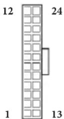
This motherboard provides a 24-pin ATX power connector. To use a 20-pin ATX power supply, please plug it along Pin 1 and Pin 13.
ATX 12V Power Connector (8-pin ATX12V1) (see p.1, No. 2)
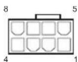
This motherboard provides a 8-pin ATX 12V power connector. To use a 4-pin ATX power supply, please plug it along Pin 1 and Pin 5.
*Warning: Please make sure that the power cable connected is for the CPU and not the graphics card. Do not plug the PCIe power cable to this connector.
eDP Signal Connector (40-pin EDP1) (see p.2, No. 17)
PIN SIGNAL
| 1 | N/A |
| 2 | LCD_BLT_VCC |
| 3 | LCD_BLT_VCC |
| 4 | LCD_BLT_VCC |
| 5 | LCD_BLT_VCC |
| 6 | N/A |
| 7 | N/A |
| 8 | eDP_VARY_BL |
| 9 | eDP_BLON |
| 10 | BKI_GND |
| 11 | BKI_GND |
| 12 | BKT_GND |
| 13 | BKT_GND |
| 14 | cDP_HPD_CON |
| 15 | PNL_GND |
| 16 | PNL_GND |
| 17 | PNL_GND |
| 18 | PNL_GND |
| 19 | N/A |
| 20 | +LVDD |
| 21 | +LVDD |
| 22 | +LVDD |
| 23 | +LVDD |
| 24 | GND |
| 25 | cDP_AUX#_CON |
| 26 | cDP_AUX_CON |
| 27 | GND |
| 28 | cDP_TX0_CON |
| 29 | eDP_TX0_CON |
| 30 | GND |
| 31 | eDP_TX1_CON |
| 32 | eDP_TX1_CON |
| 33 | GND |
| 34 | N/A |
| 35 | N/A |
| 36 | GND |
| 37 | N/A |
| 38 | N/A |
| 39 | GND |
| 40 | N/A |
This connector is for an LCD monitor that supports an internal embedded DisplayPort (eDP).
*Please refer to page 29 for further instructions on how to adjust the brightness.
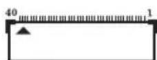
2.7 M.2\_SSD (NGFF) Module Installation Guide (M2\_1)
The M.2, also known as the Next Generation Form Factor (NGFF), is a small size and versatile card edge connector that aims to replace mPCIe and mSATA. The Ultra M.2 Socket (M2_1, Key M), supports type 2280 SATA3 6.0 Gb/s & PCIe Gen3x4 (32 Gb/s) modes.
* If M2_1 is occupied by a SATA-type M.2 device, SATA3_0 will be disabled.
Installing the M.2\_SSD (NGFF) Module
natural_image
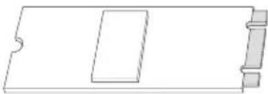
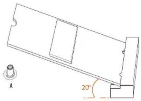
Pure technical line drawing of a rectangular component with no text or symbolsStep 1
Prepare a M.2_SSD (NGFF) module and the screw.
natural_image
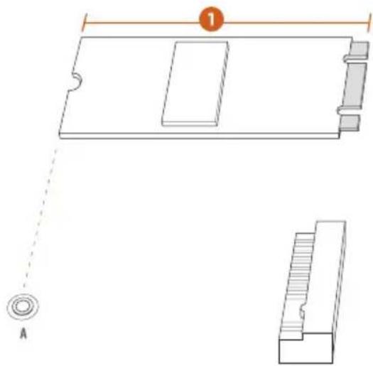
Technical line drawing of a mechanical component with dimension lines and labeled section A (no text or symbols beyond labels)Step 2
Depending on the PCB type and length of your M.2_SSD (NGFF) module, find the corresponding nut location to be used.
No.1
Nut Location A
PCB Length 8cm
Module Type Type 2280
natural_image
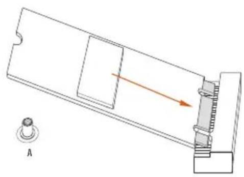
Technical diagram of a mechanical assembly with a lever and pivot, showing no text or symbolsStep 3
Align and gently insert the M.2 (NGFF) SSD module into the M.2 slot. Please be aware that the M.2 (NGFF) SSD module only fits in one orientation.
natural_image
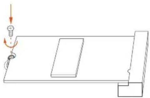
Simple line drawing of a mechanical setup with a spring, pulley, and rectangular block (no text or symbols)Step 4
Tighten the screw with a screwdriver to secure the module into place. Please do not overtighten the screw as this might damage the module.
M.2\_SSD (NGFF) Module Support List
| Vendor Interface P/N | |
| ADATA SATA3 AXNS330E-32GM-B | |
| ADATA SATA3 AXNS381E-128GM-B | |
| ADATA SATA3 AXNS381E-256GM-B | |
| ADATA SATA3 ASU800NS38-256GT-C | |
| ADATA SATA3 ASU800NS38-512GT-C | |
| ADATA PCIe3 x4 ASX7000NP-128GT-C | |
| ADATA PCIe3 x4 ASX8000NP-256GM-C | |
| ADATA PCIe3 x4 ASX7000NP-256GT-C | |
| ADATA PCIe3 x4 ASX8000NP-512GM-C | |
| ADATA PCIe3 x4 ASX7000NP-512GT-C | |
| Apacer PCIe3 x4 AP240GZ280 | |
| Corsair PCIe3 x4 CSSD-F240GBMP500 | |
| Crucial SATA3 CT120M500SSD4 | |
| Crucial SATA3 CT240M500SSD4 | |
| Intel SATA3 Intel SSDSCKGW080A401/80G | |
| Intel PCIe3 x4 SSDPEKKF256G7 | |
| Intel PCIe3 x4 SSDPEKKF512G7 | |
| Kingston SATA3 SM2280S3 | |
| Kingston PCIe3 x4 SKC1000/480G | |
| Kingston PCIe2 x4 SH2280S3/480G | |
| OCZ PCIe3 x4 RVD400 -M2280-512G (NVME) | |
| PATRIOT PCIe3 x4 PH240GPM280SSDR NVME | |
| Plextor PCIe3 x4 PX-128M8PeG | |
| Plextor PCIe3 x4 PX-1TM8PeG | |
| Plextor PCIe3 x4 PX-256M8PeG | |
| Plextor PCIe3 x4 PX-512M8PeG | |
| Plextor PCIe PX-G256M6e | |
| Plextor PCIe PX-G512M6e | |
| Samsung PCIe3 x4 SM961 MZVPW128HEGM (NVM) | |
| Samsung PCIe3 x4 PM961 MZVLW128HEGR (NVME) | |
| Samsung PCIe3 x4 960 EVO (MZ-V6E250) (NVME) | |
| Samsung PCIe3 x4 960 EVO (MZ-V6E250BW) (NVME) | |
| Samsung PCIe3 x4 SM951 (NVME) | |
| Samsung PCIe3 x4 SM951 (MZHPV256HDGL) | |
| Samsung PCIe3 x4 SM951 (MZHPV512HDGL) | |
| Samsung PCIe3 x4 SM951 (NVME) | |
| Samsung PCIe x4 XP941-512G (MZHPU512HCGL) | |
| SanDisk | PCIe SD6PP4M-128G |
| SanDisk | PCIe SD6PP4M-256G |
| Team | SATA3 TM4PS4128GMC105 |
| Team | SATA3 TM4PS4256GMC105 |
| Team | SATA3 TM8PS4128GMC105 |
| Team | SATA3 TM8PS4256GMC105 |
| TEAM PCIe3 x4 TM8FP2240G0C101 |
| TEAM PCIe3 x4 TM8FP2480GC110 |
| Transcend SATA3 TS256GMTS400 |
| Transcend SATA3 TS512GMTS600 |
| Transcend SATA3 TS512GMTS800 |
| V-Color SATA3 VLM100-120G-2280B-RD |
| V-Color SATA3 VLM100-240G-2280RGB |
| V-Color SATA3 VSM100-240G-2280 |
| V-Color SATA3 VLM100-240G-2280B-RD |
| WD SATA3 WDS100T1B0B-00AS40 |
| WD SATA3 WDS240G1G0B-00RC30 |
| WD PCIe3 x4 WDS256G1X0C-00ENX0 (NVME) |
| WD PCIe3 x4 WDS512G1X0C-00ENX0 (NVME) |
For the latest updates of M.2_SSD (NFGG) module support list, please visit our website for details: http://www.asrock.com
2.8 Change Screen Brightness for eDP in Windows®
This section explains how to change screen brightness in Windows ^® when you use an eDP panel.

The following is a setup example for Windows ^® 11. Setup procedures may vary from different operating systems.
Setup Guide
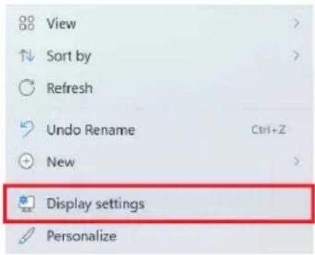
Step 1
Right click on desktop. Select Display settings.
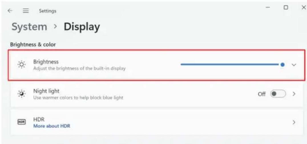
Step 2
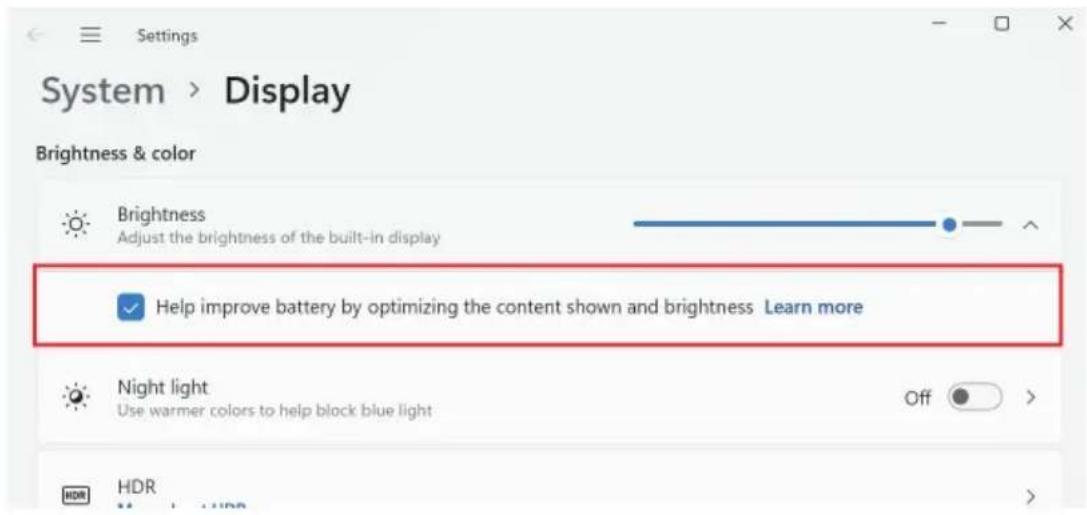
In System > Display, select Brightness. Move the slider to fine-tune the brightness level.
Step 3
You might also see another check box displayed: Help improve battery by optimizing the content shown and brightness. Select the check box to turn on the content adaptive brightness control if needed.
1 Einleitung
Cavalier Clear CMOS (CLRMOS1)
(voir p.1, No. 14)

• Supporto WOL (Wake-On-LAN)
• Supporto Energy Efficient Ethernet 802.3az
- Supporto UEFI PXE
LAN wireless
- Modulo WiFi 802.11ac
• Supporta IEEE 802.11a/b/g/n/ac
• Supporta Dual-Band (2.4/5 GHz)
If you need to contact ASRock or want to know more about ASRock, you're welcome to visit ASRock's website at http://www.asrock.com; or you may contact your dealer for further information. For technical questions, please submit a support request form at https://event.asrock.com/tsd.asp
ASRock Incorporation
e-mail: info@asrock.com.tw
ASRock EUROPE B.V.
e-mail: sales@asrock.nl
ASRock America, Inc.
e-mail: sales@asrockamerica.com