ARXN60NV1B - Air Conditioning DAIKIN - Free user manual and instructions
Find the device manual for free ARXN60NV1B DAIKIN in PDF.

User questions about ARXN60NV1B DAIKIN
0 question about this device. Answer the ones you know or ask your own.
Ask a new question about this device
Download the instructions for your Air Conditioning in PDF format for free! Find your manual ARXN60NV1B - DAIKIN and take your electronic device back in hand. On this page are published all the documents necessary for the use of your device. ARXN60NV1B by DAIKIN.
USER MANUAL ARXN60NV1B DAIKIN
ATXN25MV1B7 ARXN25MV1B7
ATXN35MV1B7 ARXN35MV1B7
ATXN50MV1B7 ARXN50MV1B7
ATXN60MV1B7 ARXN60MV1B7
ATXN25NV1B ARXN25NV1B
ATXN35NV1B ARXN35NV1B
ATXN50NV1B ARXN50NV1B
ATXN60NV1B ARXN60NV1B
Installation Manual R410A Split Series
English
text_image
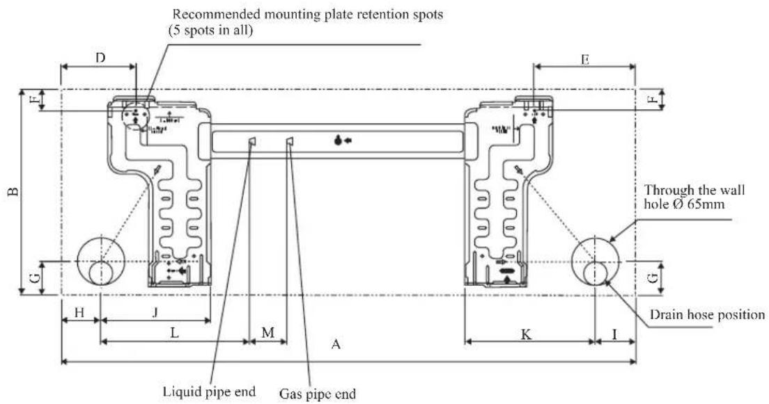
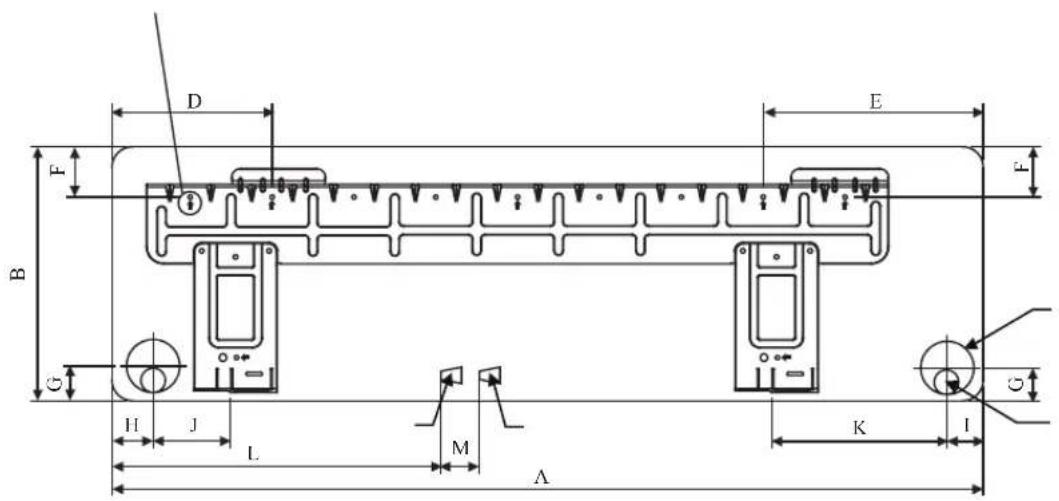
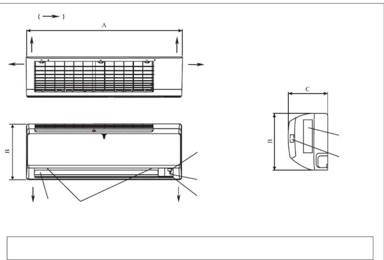
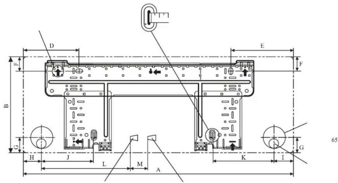
Recommended mounting plate retention spots (5 spots in all) Use tape measure as shown. Position the end of a tape measure at D E F B G H J L M A K I Through the wall hole Ø 65mm G Drain hose positionLiquid pipe end
Gas pipe end
INSTALLATION PLATE 25/35
| Dimension Model | A B | C D E | F G H | I J K L M | |||||||||
| 25/35 MV | 800 | 288 | 212 | 166 | 184 | 42 | 46 | 55 | 56 | 154 | 182 | 263 | 52 |
| 25/35 NV | 859 | 288 | 209 | 166 | 184 | 42 | 46 | 55 | 56 | 154 | 182 | 263 | 52 |
All dimensions are in mm
text_image
Recommended mounting plate retention spots (5 spots in all) Through the wall hole Ø 65mm Drain hose position Liquid pipe end Gas pipe end L M A K I G H J B D E F FALTERNATIVE INSTALLATION PLATE 25/35
All dimensions are in mm
| Dimension Model | A B | C D E | F G H I | J K L | M | |||||||
| 25/35 MV | 800 2 | 88 212 | 104 141 | 30 46 | 55 56 1 | 53 181 | 207 52 | |||||
| 25/35 NV | 859 2 | 88 209 | 104 141 | 30 46 | 55 56 1 | 53 181 | 207 52 |
text_image
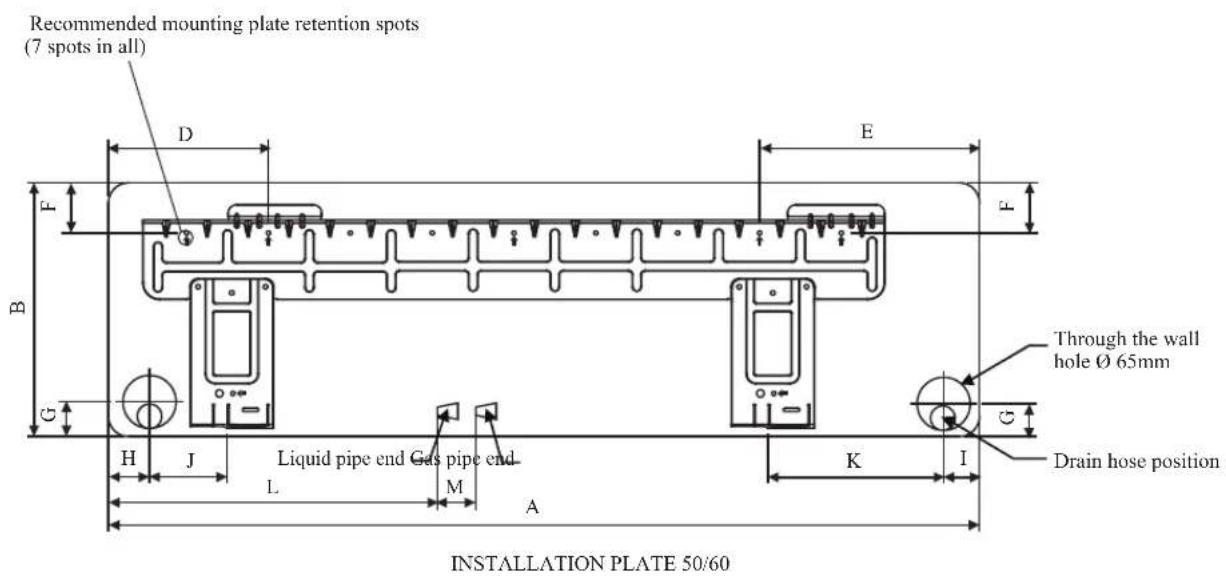
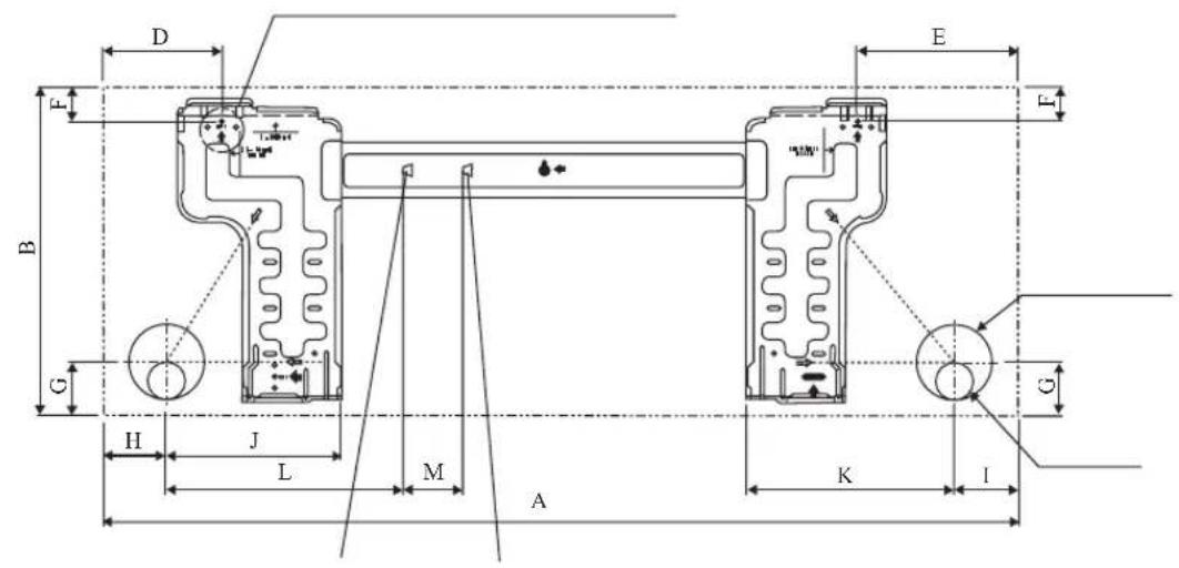
Recommended mounting plate retention spots (7 spots in all) D E F B G H J Liquid pipe end Gas pipe end L M A K I Through the wall hole Ø 65mm Drain hose position INSTALLATION PLATE 50/60All dimensions are in mm
| Dimension Model | A B | C D E | F G H I | J K L | M | |||||||
| 50/60 MV | 1065 | 310 228 | 190 173 | 61 40 | 45 48 9 | 1 219 5 | 80 45 | |||||
| 50/60 NV | 1124 | 310 237 | 190 173 | 61 40 | 45 48 9 | 1 219 5 | 80 45 |
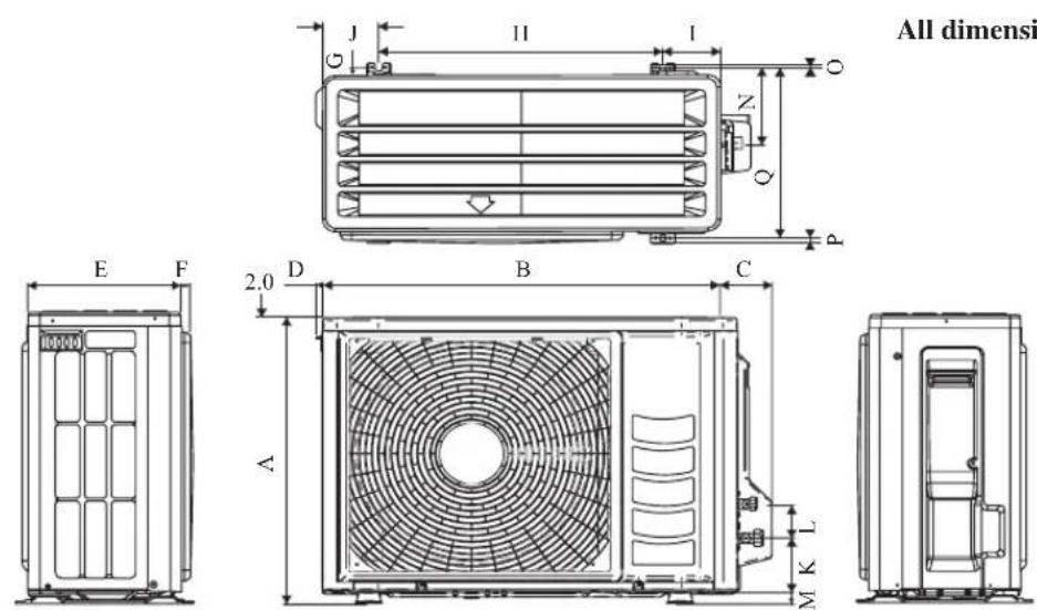
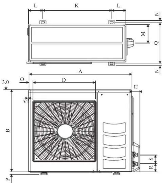
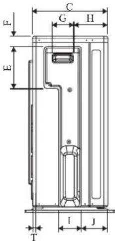
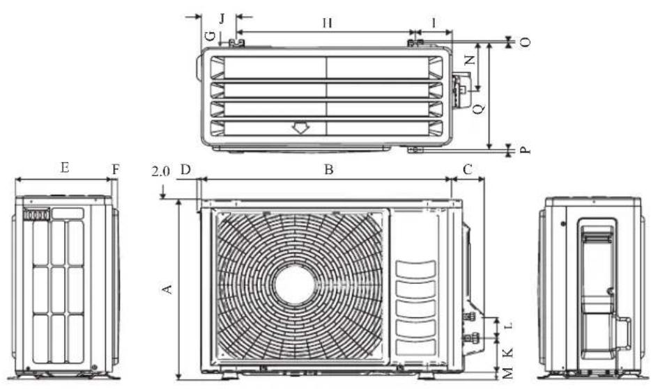
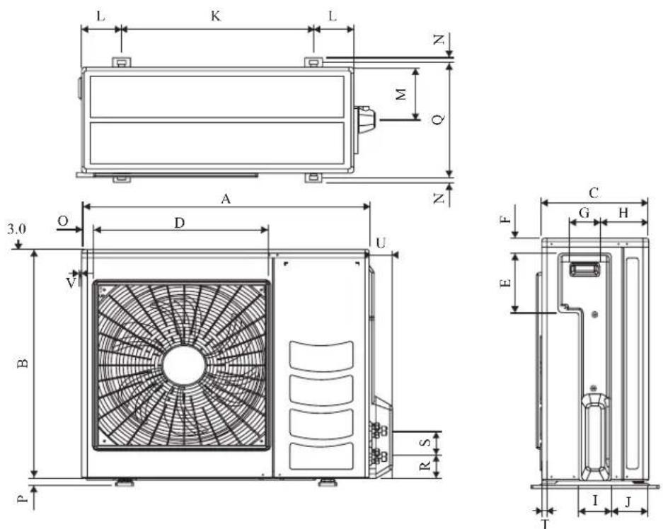
Outdoor Unit [ARXN]
All dimensions are in mm
| DimensionModel | A | B | C | D | E | F | G | H | I | J | K | L | M | N | O | P | Q | |||||||||
| 25/35 550 658 51 11 | 273 | 16 | 14 | 470 | 96 | 93 | 94 | 60 | 14 | 13 | 3 | 8 | 10 | 29 | 9 |
All dimensions are in mm
text_image
F C G H E T I J| Dimension Model | A | B | C | D | E | F | G | H | I | J | K | L | M | N | O |
| 50 NV | 855 | 628 | 328 | 520 | 179 | 46 | 93 | 149 | 101 | 113 | 603 | 126 | 164 | 15 | 34 |
| 60 NV, 50/60 MV | 855 | 730 | 328 | 520 | 179 | 46 | 93 | 149 | 101 | 113 | 603 | 126 | 164 | 15 | 34 |
| Dimension Model | P | Q | R | S | T | U | V |
| 50 NV | 23 | 362 | 73 | 75 | 8 | 67 | 7 |
| 60 NV, 50/60 MV | 23 | 362 | 73 | 75 | 8 | 67 | 7 |
INSTALLATION MANUAL
This manual provides the procedures of installation to ensure a safe and good standard of operation for the air conditioner unit.
Special adjustment may be necessary to suit local requirement.
Before using your air conditioner, please read this instruction manual carefully and keep it for future reference.
This appliance is intended to be used by expert or trained users in shops, in light industry and on farms, or for commercial use by lay persons.
This appliance is not intended for use by persons, including children, with reduced physical, sensory or mental capabilities, or lack of experience and knowledge, unless they have been given supervision or instruction concerning use of the appliance by a person responsible for their safety.
Children should be supervised to ensure that they do not play with the appliance.
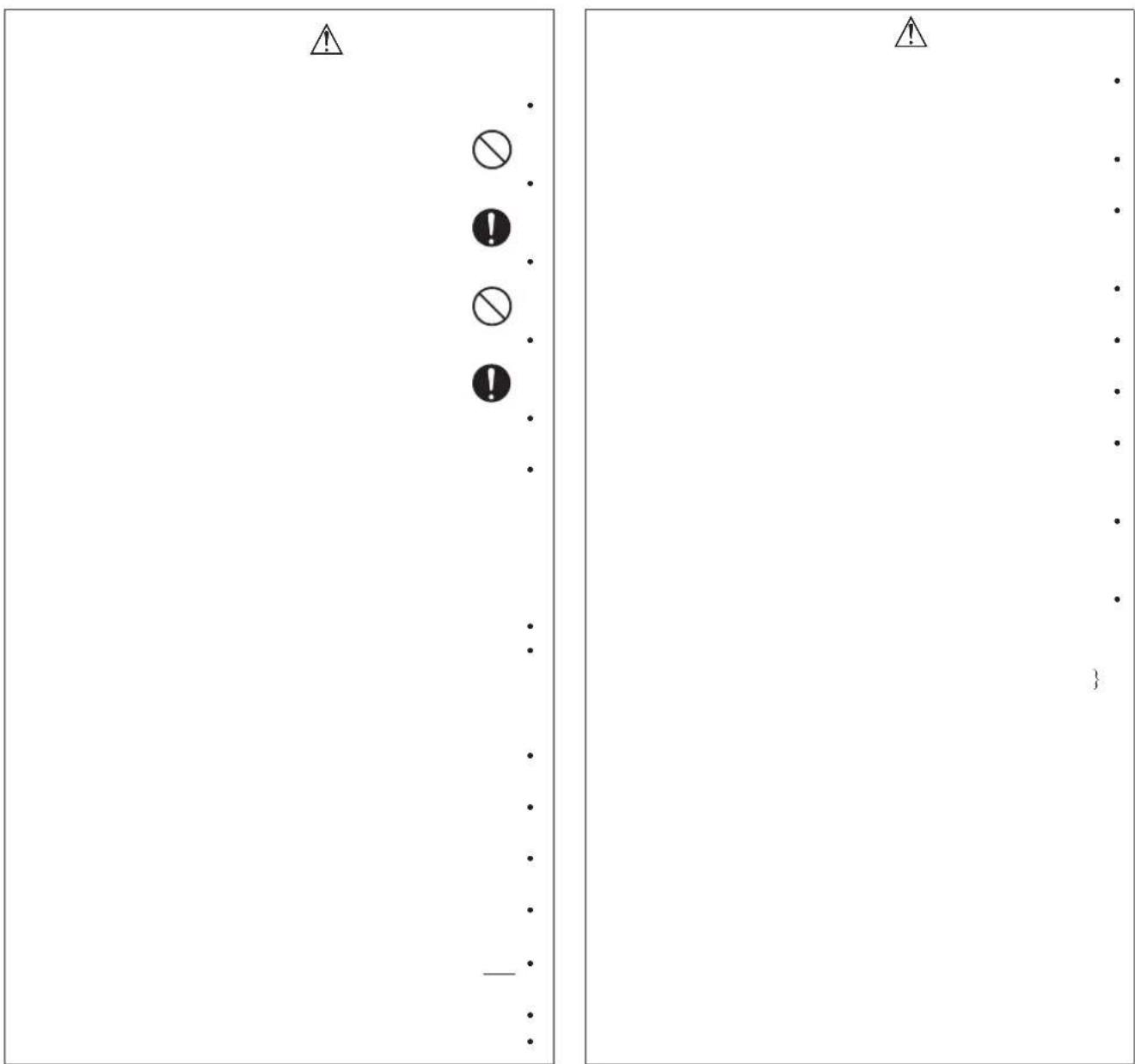
SAFETY PRECAUTIONS
⚠ WARNING ⚠ CAUTION
- Installation and maintenance should be performed by qualified persons who are familiar with local code and regulation, and experienced with this type of appliance.
- All field wiring must be installed in accordance with the national wiring regulation.
- Ensure that the rated voltage of the unit corresponds to that of the name plate before commencing wiring work according to the wiring diagram.
- The unit must be GROUNDED to prevent possible hazard due to insulation failure.
- All electrical wiring must not touch the water piping or any moving parts of the fan motors.
- Confirm that the unit has been switched OFF before installing or servicing the unit.
- Risk of electric shock, can cause injury or death. Disconnect all remain electric power supplies before servicing.
- DO NOT pull out the power cord when the power is ON. This may cause serious electrical shocks which may result in the fire hazards.
- Keep the indoor and outdoor units, power cable and transmission wiring, at least 1m from TVs and radios, to prevent distorted pictures and static. {Depending on the type and source of the electrical waves, static may be heard even when more than 1m away}.
Please take note of the following important points when installing.
- Do not install the unit where leakage of fl ammable gas may occur.
If gas leaks and accumulates around the unit, it may cause f re ignition.
- Ensure that drainage piping is connected properly.
If the drainage piping is not connected properly, it may cause water leakage which will dampen the furniture.
- Do not overcharge the unit.
This unit is factory pre-charged.
Overcharge will cause over-current or damage to the compressor.
- Ensure that the unit's panel is closed after service or installation.
Unfired panels will cause the unit to operate noisily.
- Sharp edges and coil surfaces are potential locations which may cause injury hazards. Avoid from being in contact with these places.
- Before turning off the power supply, set the remote controller's ON/OFF switch to the "OFF" position to prevent the nuisance tripping of the unit. If this is not done, the unit's fans will start turning automatically when power resumes, posing a hazard to service personnel or the user.
- Do not install the units at or near doorway.
- Do not operate any heating apparatus too close to the air conditioner unit or use in room where mineral oil, oil vapour or oil steam exist, this may cause plastic part to melt or deform as a result of excessive heat or chemical reaction.
- When the unit is used in kitchen, keep fl our away froming into suction of the unit.
- This unit is not suitable for factory used where cutting oil mist or iron powder exist or voltage fluctuates greatly.
- Do not install the units at area like hot spring or oil refi nery plant where sulphide gas exists.
- Ensure the color of wires of the outdoor unit and the terminal markings are same to the indoors respectively.
- IMPORTANT: DO NOT INSTALL OR USE THE AIR CONDITIONER UNIT IN A LAUNDRY ROOM.
- Don't use joined and twisted wires for incoming power supply.
- The equipment is not intended for use in a potentially explosive atmosphere.
NOTICE
Disposal requirements
Your air conditioning product is marked with this symbol. This means that electrical and electronic products shall not be mixed with unsorted household waste.
Do not try to dismantle the system yourself: the dismantling of the air conditioning system, treatment of the refrigerant, of oil and of other parts must be done by a qualified installer in accordance with relevant local and national legislation.
Air conditioners must be treated at a specialized treatment facility for re-use, recycling and recovery. By ensuring this product is disposed of correctly, you will help to prevent potential negative consequences for the environment and human health. Please contact the installer or local authority for more information.
Batteries must be removed from the remote controller and disposed of separately in accordance with relevant local and national legislation.
IMPORTANT
Important information regarding the refrigerant used
This product contains fluorinated greenhouse gases.
Do not vent gases into the atmosphere.
Refrigerant type: R410A
GWP ^(1) value: 2087.5
(1) GWP = Global Warming Potential
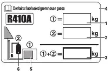
Please fill in with indelible ink,
① the factory refrigerant charge of the product,
② the additional refrigerant amount charged in the field and
① + ② the total refrigerant charge
on the refrigerant charge label supplied with the product.
The filled out label must be adhered in the proximity of the product charging port (e.g. onto the inside of the service cover).
text_image
Contains fluorinated greenhouse gases R410A ①=kg ②=kg ①+②=kg 6 5 31 factory refrigerant charge of the product: see unit name plate ^(2)
2 additional refrigerant amount charged in the field
3 total refrigerant charge
4 contains fluorinated greenhouse gases
5 outdoor unit
6 refrigerant cylinder and manifold for charging
^(2) In case of multiple indoor systems, only 1 label must be adhered*, mentioning the total factory refrigerant charge of all indoor units connected in the refrigerant system.
Periodical inspections for refrigerant leaks may be required depending on European or local legislation. Please contact your local dealer for more information.
* on the outdoor unit
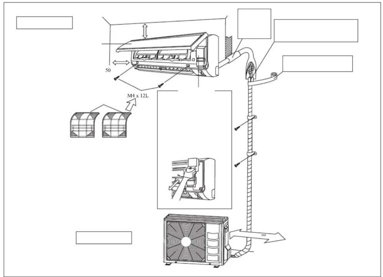
INSTALLATION DIAGRAM
text_image
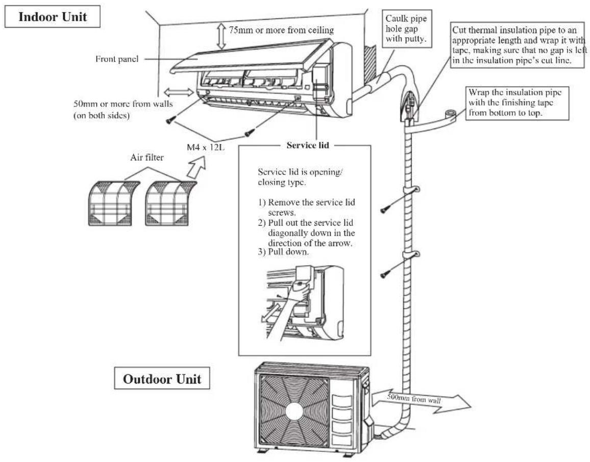
Indoor Unit Front panel 75mm or more from ceiling Caulk pipe hole gap with putty. Cut thermal insulation pipe to an appropriate length and wrap it with tape, making sure that no gap is left in the insulation pipe's cut line. 50mm or more from walls (on both sides) M4 x 12L Service lid Air filter Service lid is opening/ closing type. 1) Remove the service lid screws. 2) Pull out the service lid diagonally down in the direction of the arrow. 3) Pull down. 500mm from wall Wrap the insulation pipe with the finishing tape from bottom to top. Outdoor UnitINSTALLATION OF THE OUTDOOR UNIT
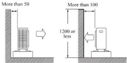
- Where a wall or other obstacle is in the path of outdoor unit's intake or exhaust airflow, follow the installation guidelines below.
- For any of the below installation patterns, the wall height on the exhaust side should be 1200mm or less.
Wall facing one side
text_image
More than 50 More than 100 1200 or lessSide View
Wall facing two sides
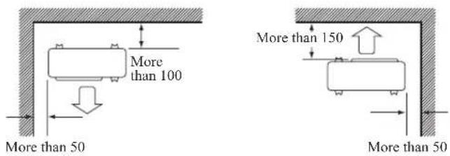
text_image
More than 100 More than 50 More than 150 More than 50Top View
Wall facing three sides
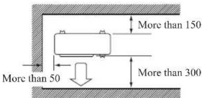
text_image
More than 150 More than 50 More than 300Top View
Unit: mm
Drain work. (Heat Pump Unit Only)
1) Use drain plug for drainage.
2) If the drain port is covered by a mounting base or floor surface, place additional foot bases of at least 30mm in height under the outdoor unit's feet.
3) In cold areas, do not use a drain hose with the outdoor unit. (Otherwise, drain water may freeze, impairing heating performance.)
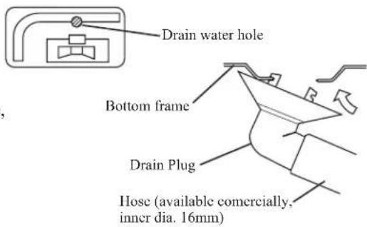
text_image
Drain water hole Bottom frame Drain Plug Hose (available commercially, inner dia. 16mm)INSTALLATION OF THE OUTDOOR UNIT
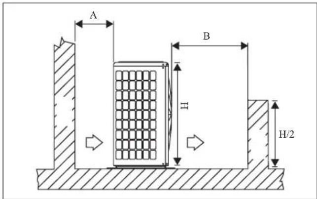
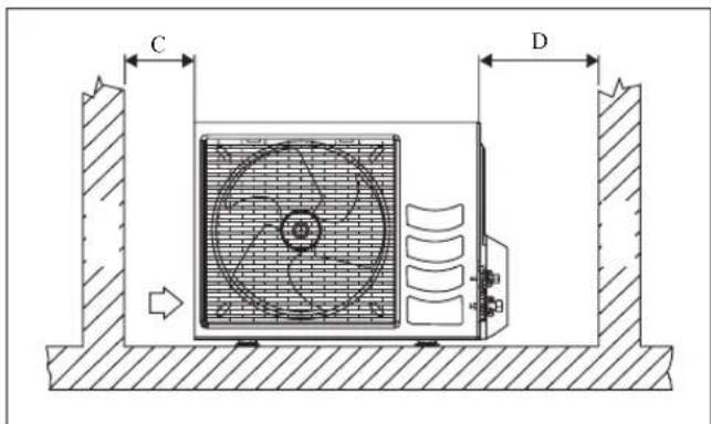
The outdoor unit must be installed in such a way, so as to prevent short circuit of the hot discharged air or obstruction to the smooth air flow. Please follow the installation clearances shown in the figure. Select the coolest possible place where intake air temperature is not greater than the outside air temperature (Refer to operating range).
Installation clearances
| Dimension | A B C D | ||
| Minimum Distance, mm | 300 100 0 300 500 |
Note: If there is any obstacle higher than half, of the unit's height (H), please allow more space than the figure indicated in the above table.
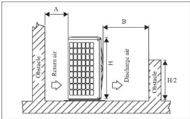
text_image
A Return air B H Discharge air Obstacle H/2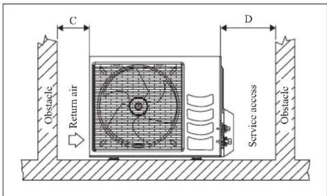
text_image
C Return air D Service access Obstacle ObstacleCondensed Water Disposal Of Outdoor Unit (Heat Pump Unit Only)
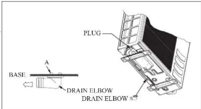
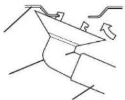
- There are 2 holes on the base of Outdoor Unit for condensed water to flow out. Insert the drain elbow to one of the holes.
- To install the drain elbow, first insert one portion of the hook to the base (portion A), then pull the drain elbow in the direction shown by the arrow while inserting the other portion to the base. After installation, check to ensure that the drain elbow clings to base firmly.
- If the unit is installed in a snowy and chilly area, condensed water may freeze in the base. In such case, please remove plug at the bottom of unit to smooth the drainage.
text_image
BASE A PLUG DRAIN ELBOW DRAIN ELBOW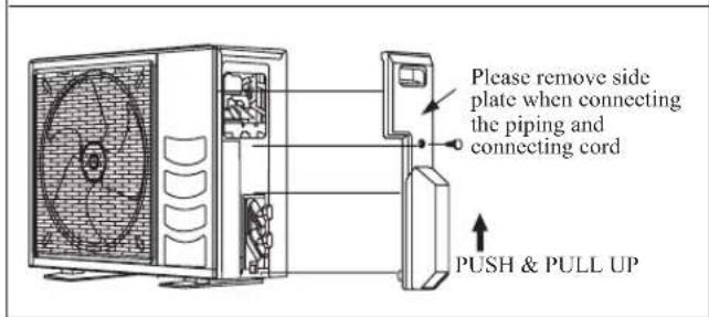
text_image
Please remove side plate when connecting the piping and connecting cord PUSH & PULL UPINSTALLATION OF THE INDOOR UNIT
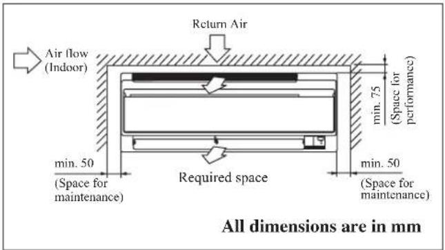
The indoor unit must be installed in such a way so as to prevent The refrigerant piping can be routed to the unit in a number short circuit of the cool discharged air with the hot return air. of ways (left or right from the back of the unit), by using the Please follow the installation clearance shown in the figure. Do cut-out holes on the casing of the unit (see figure). Bend the not place the indoor unit where there could be direct sunlight shining on it. Also, this location must be suitable for piping and drainage, and be away from doors or windows. The condensation drain hose can be taped to the pipes.
text_image
Return Air Air flow (Indoor) min. 50 (Space for maintenance) Minimum 75 (Space for performance) Minimum 50 (Space for maintenance) Required space All dimensions are in mmRight-side, right-back or right-bottom piping
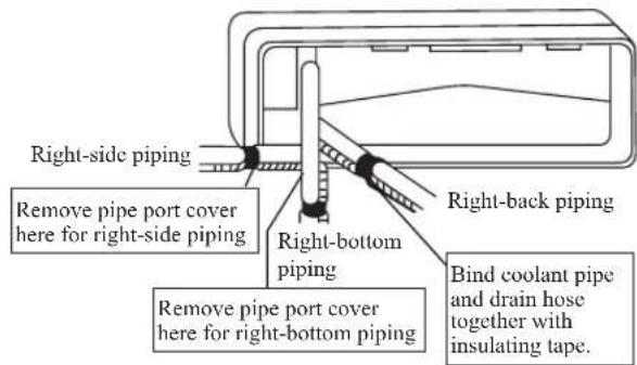
text_image
Right-side piping Remove pipe port cover here for right-side piping Right-bottom piping Bind coolant pipe and drain hose together with insulating tape. Remove pipe port cover here for right-bottom pipingLeft-side, left-back or left-bottom piping
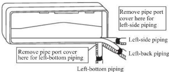
text_image
Remove pipe port cover here for left-side piping Left-side piping Remove pipe port cover here for left-bottom piping Left-back piping Left-bottom pipingMounting Installation Plate
Ensure that the wall is strong enough to withstand the weight of the unit. Otherwise, it is necessary to reinforce the wall with plates, beams or pillars. Use the level gauge for horizontal mounting, fix it with 5 suitable screws for 20/35 and 7 suitable screws for 50/60. In case the rear piping draws out, drill a hole 65mm in diameter with a cone drill, slightly lower on the outside wall (see figure).
20/35 (ALTERNATIVE INSTALLATION PLATE)
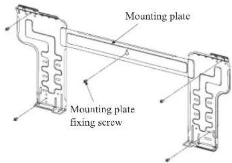
text_image
Mounting plate Mounting plate fixing screw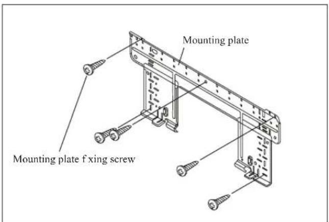
text_image
Mounting plate Mounting plate f xing screw50/6020/35
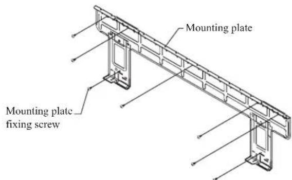
text_image
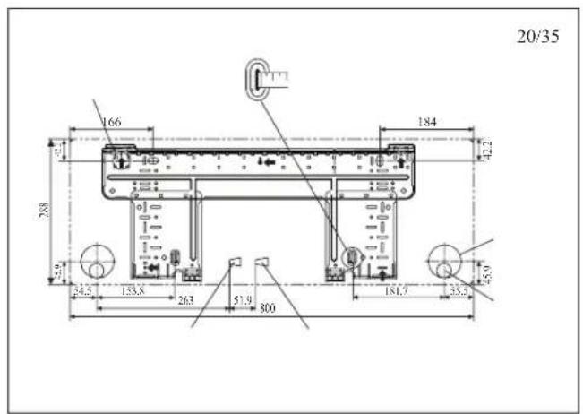
Mounting plate Mounting plate fixing screwRecommended Mounting Plate Retention Spots And Dimensions
20/35
Recommended mounting plate retention spots (5 spots in all) Use tape measure as shown. Position the end of a tape measure at
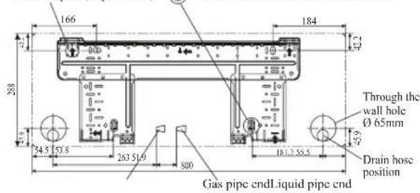
text_image
166 288 54.5 53.8 263 51.9 800 184 42.2 Through the wall hole Ø 65mm Drain hose position Gas pipe endLiquid pipe endAll dimensions are in mm
20/35 (ALTERNATIVE INSTALLATION PLATE)
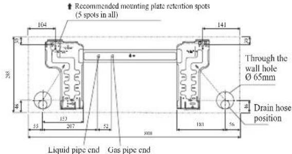
text_image
Recommended mounting plate retention spots (5 spots in all) Through the wall hole Ø 65mm Drain hose position Liquid pipe end Gas pipe endAll dimensions are in mm
50/60
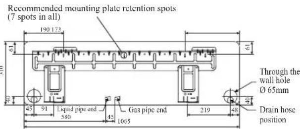
text_image
Recommended mounting plate retention spots (7 spots in all) 190 173 61 45 91 Liquid pipe end 580 45 1065 219 48 Through the wall hole Ø 65mm Drain hose positionAll dimensions are in mm
Hole With Cone Drill
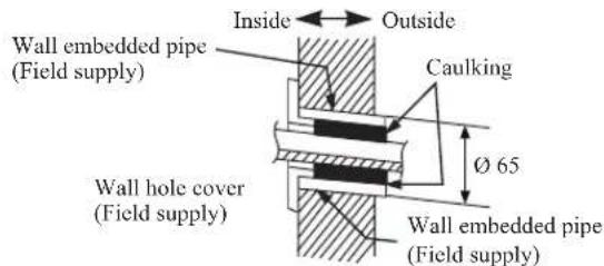
text_image
Inside Outside Wall embedded pipe (Field supply) Caulking Ø 65 Wall hole cover (Field supply) Wall embedded pipe (Field supply)Mount The Unit Onto The Installation Plate
Hook the indoor unit onto the upper portion of the installation plate (Engage the two hooks at the rear top of the indoor unit with the upper edge of the installation plate). Ensure that the hooks are properly seated on the installation plate by moving it to the left and right.
How To Attach The Indoor Unit
Hook the claws of the bottom frame to the mounting plate.
How To Remove The Indoor Unit
Push up the marked area (at the lower part of the front grille) to release the claws.
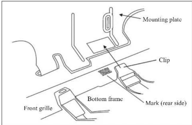
text_image
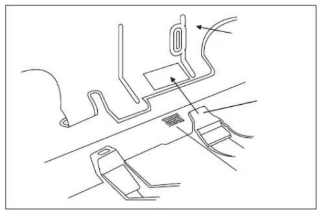
Mounting plate Clip Bottom frame Front grille Mark (rear side)Hang indoor unit's hook here.
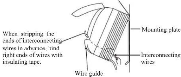
text_image
When stripping the ends of interconnecting wires in advance, bind right ends of wires with insulating tape. Mounting plate Interconnecting wires Wire guideWater Drainage Piping
The indoor drain pipe must be in a downward gradient for smooth drainage. Avoid situations that are likely to cause water to leak.
Water Drainage
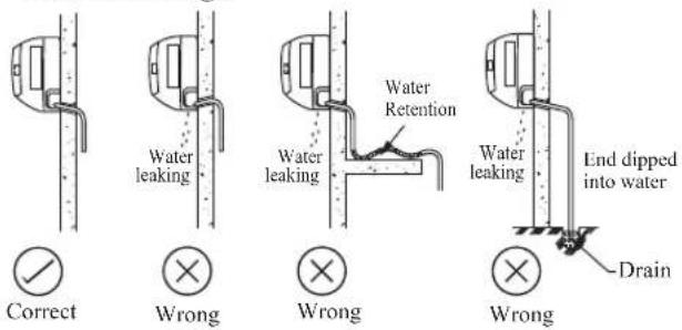
text_image
Correct Wrong Wrong Wrong Water leaking Water leaking Water Retention Water leaking End dipped into water Drain
CAUTION
- Do not install the unit at altitude over 2000m for both indoor and outdoor.
REFRIGERANT PIPING
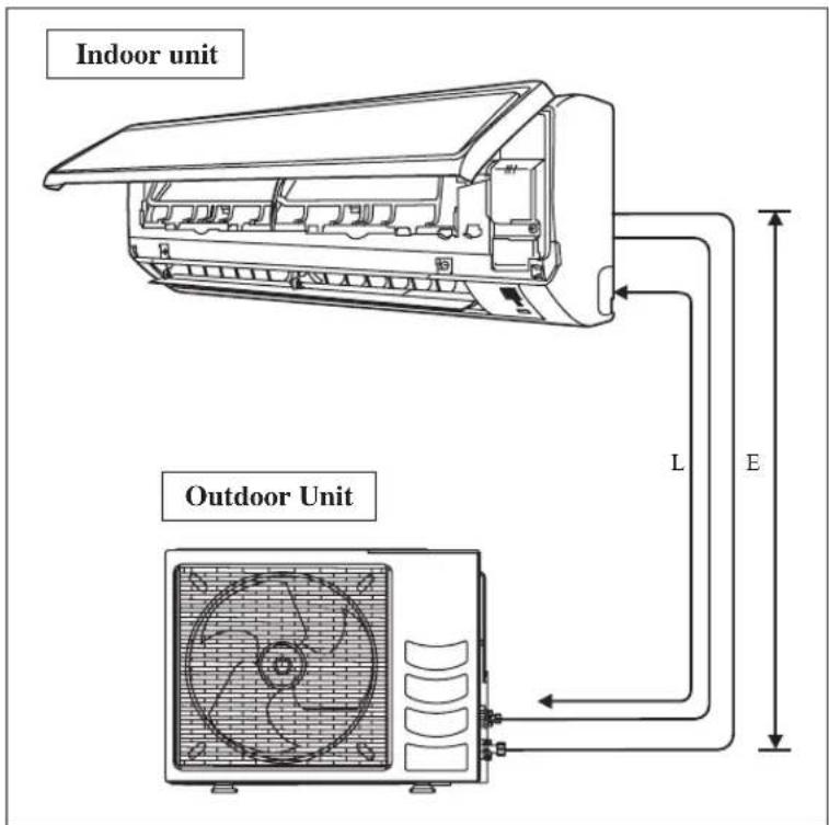
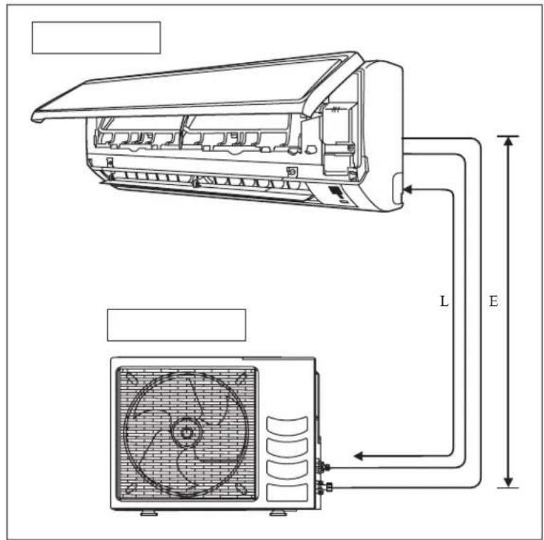
Allowable Piping Length
If the pipe is too long, both the capacity and reliability of the unit will drop. As the number of bends increases, resistance to the flow of refrigerant system increases, thus lowering cooling capacity. As a result, the compressor may become defective. Always choose the shortest path and follow the recommendations as tabulated below:
text_image
Indoor unit Outdoor Unit L E| Model (ATXN) | 25 35 50 60 | ||
| Min. Allowable Length (L), m | 3 | 3 | |
| Max. Allowable Length (L), m | 20 30 | ||
| Max. Allowable Elevation (E), m | 10 10 | ||
| Gas Pipe Size, mm/(in) | 9.52 (3/8") 12.70 (1/2") 15.88 (5/8") | ||
| Liquid Pipe Size, mm/(in) | 6.35 (1/4") 6.35 (1/4") | ||
*Be sure to add the proper amount of additional refrigerant. Failure to do so may result in reduced performance.
Remark: The refrigerant pre-charged in the outdoor unit is for piping length up to 7.5m.
Equivalent length for various fitting (meter)
| Pipe Size L joint |  | Trap bend |
| 3/8" (OD9.52mm) 0.18 1.3 | ||
| 1/2" (OD12.7mm) 0.20 1.5 | ||
| 5/8" (OD15.9mm) 0.25 2 | ||
| 3/4" (OD19.1mm) 0.35 2.4 | ||
| 7/8" (OD22.2mm) 0.40 3 | ||
| 1" (OD25.4mm) 0.45 3.4 | ||
| 1 1/8" (OD28.6mm) 0.50 3.7 | ||
| 1 3/8" (OD34.9mm) 0.60 4.4 |
Notes:
1. Equivalent piping length is obtained with actual length of gas piping.
2. 90° bend of piping is equivalent to L joint.
Bending must be carefully made so as not to crush the pipe. Use a pipe bender to bend a pipe where possible.
REFRIGERANT PIPING
Piping Works And Flaring Technique
- Do not use contaminated or damaged copper tubing. If any piping, evaporator or condenser had been exposed or had been opened for 15 seconds or more, the system must be vacuumed. Generally do not remove plastic, rubber plugs and brass nuts from the valves, fittings, tubing and coils until it is ready to connect suction or liquid line into valves or fittings.
- If any brazing work is required, ensure that nitrogen gas is passed through coil and joints while the brazing work is being done. This will eliminate soot formation on the inside wall of copper tubings.
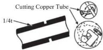
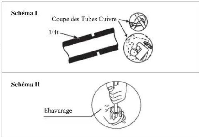
- Cut the pipe stages by stages, advancing the blade of pipe cutter slowly. Extra force and a deep cut will cause more distortion of pipe and therefore extra burr. See Figure I.
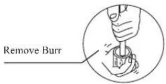
- Remove burrs from cut edges of the pipes with remover. See Figure II. Hold the pipe on top position and burr remover at lower position to prevent metal chips from entering the pipe. This will avoid unevenness on the flare faces which will cause gas leak.
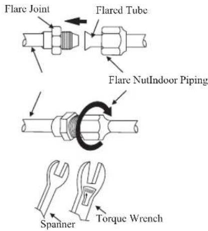
- Insert the flare nuts, mounted on the connection parts of both the indoor unit and outdoor unit, into the copper pipes.
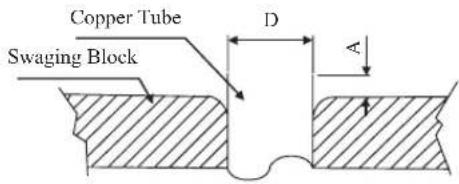
- The exact length of pipe protruding from the top surface of the swaging block is determined by the flaring tool. See Figure III.
- Fix the pipe firmly on the swaging block. Match the centers of both the swaging block and the flaring punch, then tighten the flaring punch fully.
- The refrigerant pipe connection are insulated by closed cell polyurethane.
Piping Connection To The Units
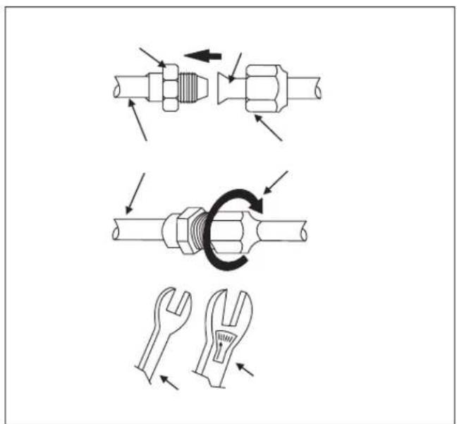
- Align the center of the piping and tighten the flare nut sufficiently with fingers. See Figure IV.
• Finally, tighten the flare nut with torque wrench until the wrench clicks. - When tightening the flare nut with the torque wrench, ensure that the tightening direction follows the arrow indicated on the wrench.
- The refrigerant pipe connection are insulated by closed cell polyurethane.
| Pipe Size, mm (in) Torque, Nm/(ft-lb) | |
| 6.35 (1/4") 18 (13.3) | |
| 9.52 (3/8") 42 (31.0) | |
| 12.70 (1/2") 55 (40.6) | |
| 15.88 (5/8") 65 (48.0) | |
| 19.05 (3/4") 78 (57.6) | |
Figure 1
text_image
Cutting Copper Tube 1/4tFigure II
text_image
Remove BurrFigure III
text_image
Copper Tube Swaging Block D A| ∅ Tube, D A (mm) | |||
| Inch mm | Imperial(Wing-nut Type) | Rigid(Clutch Type) | |
| 1/4" 6.35 | 1.3 | 0.7 | |
| 3/8" 9.52 | 1.6 | 1.0 | |
| 1/2" | 12.70 | 1.9 | 1.3 |
| 5/8" | 15.88 | 2.2 | 1.7 |
| 3/4" | 19.05 | 2.5 | 2.0 |
Figure IV
text_image
Flare Joint Flared Tube Flare NutIndoor Piping Spanner Torque WrenchELECTRICAL WIRING CONNECTION
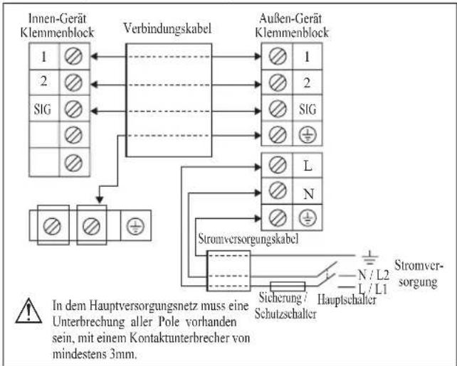
IMPORTANT :
* The figures shown in the table are for information purpose only. They should be checked and selected to comply with the local/national codes of regulations. This is also subject to the type of installation and conductors used.
** The appropriate voltage range should be checked with label data on the unit.
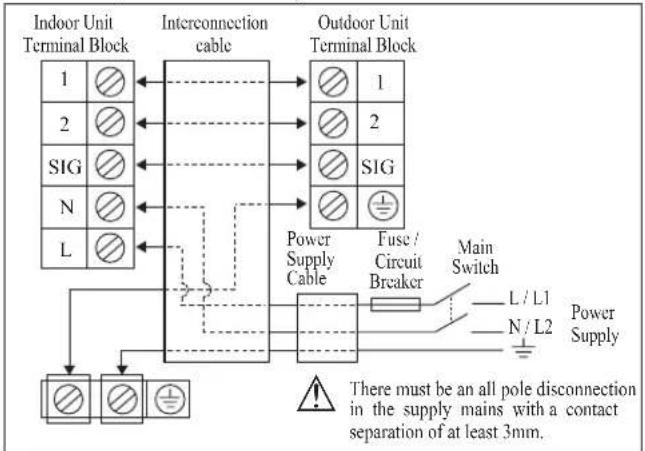
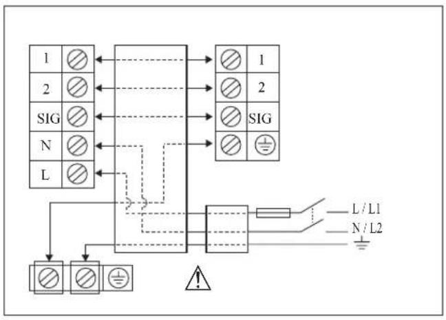
Inverter (Power Indoor)
flowchart
graph TD
    A["Indoor Unit Terminal Block"] --> B["Interconnection cable"]
    B --> C["Outdoor Unit Terminal Block"]
    D["Indoor Unit Terminal Block"] --> E["Power Supply Cable"]
    E --> F["Fuse / Circuit Breaker"]
    F --> G["Main Switch"]
    G --> H["L/L1"]
    G --> I["N/L2"]
    H --> J["Power Supply"]
    I --> J
    J --> K["There must be an all pole disconnection in the supply mains with a contact separation of at least 3mm."]
    style A fill:#f9f,stroke:#333
    style B fill:#ccf,stroke:#333
    style C fill:#cfc,stroke:#333
    style D fill:#fcc,stroke:#333
    style E fill:#cff,stroke:#333
    style F fill:#ffc,stroke:#333
    style G fill:#fcf,stroke:#333
    style H fill:#cff,stroke:#333
    style I fill:#ffc,stroke:#333
    style J fill:#cfc,stroke:#333
    style K fill:#fcc,stroke:#333
| Model Indoor (ATXN) | 25 35 50 60 | |||
| Outdoor (ARXN) | 25 35 50 60 | |||
| Voltage range ** | 220-240V/-/50Hz + ➊ | |||
| Power supply cable size* mm2Number of conductors | 1.5 | 2.5 | ||
| 3 | 3 | |||
| Interconnection cable size* mm2Number of conductors | 1.5 | 2.5 | ||
| 4 | 4 | |||
| Recommended fuse /circuit breaker rating A 16 20 | ||||
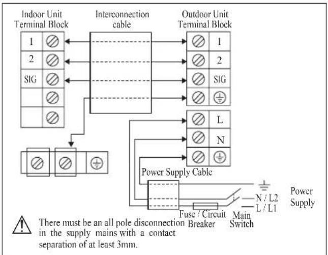
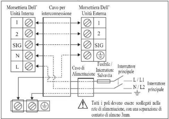
Inverter (Power Outdoor)
flowchart
graph TD
    A["Indoor Unit Terminal Block"] --> B["Interconnection cable"]
    C["Outdoor Unit Terminal Block"] --> B
    B --> D["Power Supply Cable"]
    D --> E["Fuse / Circuit Breaker"]
    E --> F["Main Switch"]
    F --> G["N / L2"]
    F --> H["L / L1"]
    G --> I["Power Supply"]
    H --> I
    J["SIG"] --> B
    K["+"] --> B
    L["+"] --> B
    M["+"] --> B
    N["+"] --> B
    O["+"] --> B
    P["+"] --> B
    Q["+"] --> B
    R["+"] --> B
    S["+"] --> B
    T["+"] --> B
    U["+"] --> B
    V["+"] --> B
    W["+"] --> B
    X["+"] --> B
    Y["+"] --> B
    Z["+"] --> B
    AA["+"] --> B
    AB["+"] --> B
    AC["+"] --> B
    AD["+"] --> B
    AE["+"] --> B
    AF["+"] --> B
    AG["+"] --> B
    AH["+"] --> B
    AI["+"] --> B
    AJ["+"] --> B
    AK["+"] --> B
    AL["+"] --> B
    AM["+"] --> B
    AN["+"] --> B
    AO["+"] --> B
    AP["+"] --> B
    AQ["+"] --> B
    AR["+"] --> B
    AS["+"] --> B
    AT["+"] --> B
    AU["+"] --> B
    AV["+"] --> B
    AW["+"] --> B
    AX["+"] --> B
    AY["Indoor Unit Terminal Block"] --> AZ["Interior Connection Cable"]
    AZ --> BA["Outdoor Unit Terminal Block"]
    style AZ fill:#f9f,stroke:#333,stroke-width:2px
    note right of AZ There must be an all pole disconnection in the supply mains with a contact separation of at least 3mm.
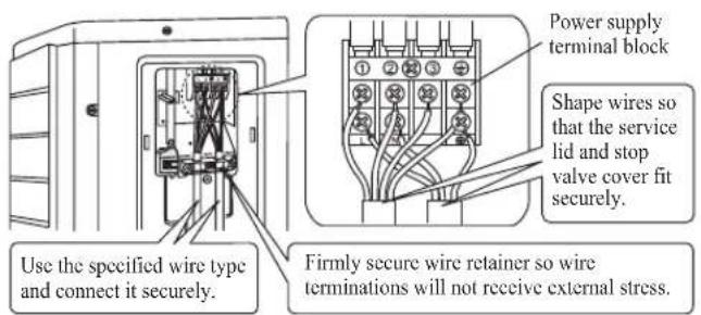
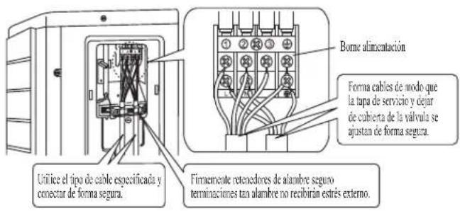
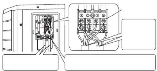
text_image
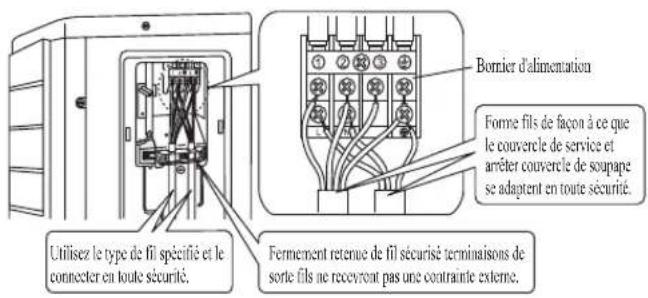
Use the specified wire type and connect it securely. Power supply terminal block Shape wires so that the service lid and stop valve cover fit securely. Firmly secure wire retainer so wire terminations will not receive external stress.• All wires must be firmly connected.
• Make sure all the wire do not touch the refrigerant pipings, compressor or any moving parts.
• The connecting wire between the indoor unit and the outdoor unit must be clamped by using provided cord anchorage.
- The power supply cord must be equivalent to H07RN-F which is the minimum requirement.
- Make sure no external pressure is applied to the terminal connectors and wires.
• Make sure all the covers are properly fixed to avoid any gap.
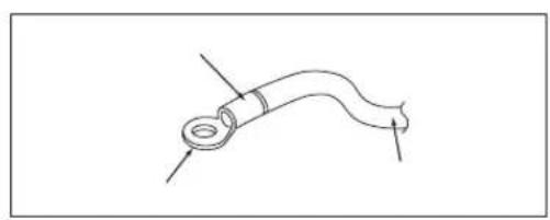
- Use round crimp-style terminal for connecting wires to the power supply terminal block. Connect the wires by matching to the indication on terminal block. (Refer to the wiring diagram attached on the unit).
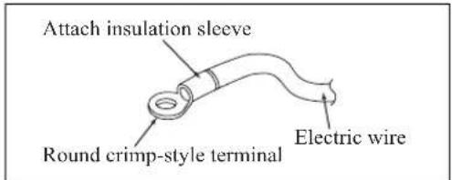
text_image
Attach insulation sleeve Round crimp-style terminal Electric wire• Used the correct screwdriver for terminal screws tightening. Unsuitable screwdrivers can damage the screw head.
• Over tightening can damage the terminal screws.
- Do not connect wire of different gauge to same terminal.
- Keep wiring in an orderly manner. Prevent the wiring from obstructing other parts and the terminal box cover.
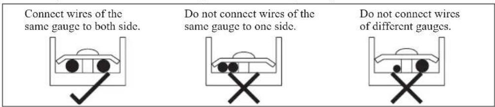
text_image
Connect wires of the same gauge to both side. Do not connect wires of the same gauge to one side. Do not connect wires of different gauges.SPECIAL PRECAUTIONS WHEN DEALING WITH R410A UNIT
R410A is a new HFC refrigerant which does not damage the ozone layer. The working pressure of this new refrigerant is 1.6 times higher than conventional refrigerant (R22), thus proper installation/servicing is essential.
- Never use refrigerant other than R410A in an air conditioner which is designed to operate with R410A.
- POE or PVE oil is used as lubricant for R410A compressor, which is different from the mineral oil used for R22 compressor. During installation or servicing, extra precaution must be taken not to expose the R410A system too long to moist air. Residual POE or PVE oil in the piping and components can absorb moisture from the air.
-
To prevent mischarging, the diameter of the service port on the flare valve is different from that of R22.
-
Use tools and materials exclusively for refrigerant R410A. Tools exclusively for R410A are manifold valve, charging hose, pressure gauge, gas leak detector, flare tools, torque wrench, vacuum pump and refrigerant cylinder.
As an R410A air conditioner incurs higher pressure than R22 units, it is essential to choose the copper pipes correctly. Never use copper pipes thinner than 0.8mm even though they are available in the market.
If the refrigerant gas leakage occurs during installation/servicing, be sure to ventilate fully. If the refrigerant gas comes into contact with fire, a poisonous gas may occur. - When installing or removing an air conditioner, do not allow air or moisture to remain in the refrigerant cycle.
VACUUMING AND CHARGING
Vacuuming is necessary to eliminate all moisture and air from the system.
Vacuuming The Piping And The Indoor Unit
Except for the outdoor unit which is pre-charged with refrigerant, the indoor unit and the refrigerant connection pipes must be air-purged because the air containing moisture that remains in the refrigerant cycle may cause malfunction of the compressor.
- Remove the caps from the valve and the service port.
- Connect the center of the charging gauge to the vacuum pump.
- Connect the charging gauge to the service port of the 3-way valve.
- Start the vacuum pump. Evacuate for approximately 30 minutes. The evacuation time varies with different vacuum pump capacity. Confirm that the charging gauge needle has moved towards -760mmHg.
Caution
- If the gauge needle does not move to -760mmHg, be sure to check for leakage at flare type connection of the indoor and outdoor unit and repair the leak before proceeding to the next step.
- Close the valve of the changing gauge and stop the vacuum pump.
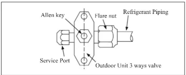
- On the outdoor unit, open the suction valve (3 way) and liquid valve (2 way) (in anti-clockwise direction) with 4mm key for hexagon sacked screw.
text_image
Allen key Flare nut Refrigerant Piping Service Port Outdoor Unit 3 ways valve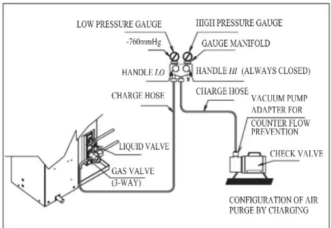
text_image
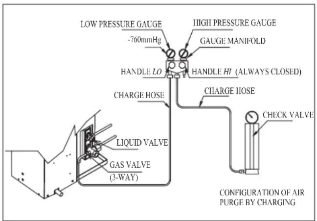
LOW PRESSURE GAUGE -760mmHg IIGII PRESSURE GAUGE GAUGE MANIFOLD HANDLE LO HANDLE HI (ALWAYS CLOSED) CHARGE HOSE VACUUM PUMP ADAPTER FOR COUNTER FLOW PREVENTION LIQUID VALVE GAS VALVE (3-WAY) CHECK VALVE CONFIGURATION OF AIR PURGE BY CHARGINGCharge Operation
This operation must be done by using a gas cylinder and a precise weighing machine. The additional charge is topped-up into the outdoor unit using the suction valve via the service port.
- Remove the service port cap.
- Connect the low pressure side of the charging gauge to the suction service port center of the cylinder tank and close the high pressure side of the gauge. Purge the air from the service hose.
- Start the air conditioner unit.
- Open the gas cylinder and low pressure charging valve.
- When the required refrigerant quantity is pumped into the unit, close the low pressure side and the gas cylinder valve.
- Disconnect the service hose from service port. Put back the service port cap.
text_image
LOW PRESSURE GAUGE -760mmHg IIGII PRESSURE GAUGE GAUGE MANIFOLD HANDLE LO HANDLE HI (ALWAYS CLOSED) CHARGE HOSE LIQUID VALVE GAS VALVE (3-WAY) CIIARGE IIOSE CHECK VALVE CONFIGURATION OF AIR PURGE BY CHARGINGADDITIONAL CHARGE
The refrigerant is pre-charged in the outdoor unit. If the piping length is less than 7.5m, then additional charge after vacuuming is not necessary. If the piping length is more than 7.5m, then use the additional charge value as indicated in the table. Additional refrigerant charge [g] per additional 1m length as tabulated
| Indoor (ATXN) | 25 35 50 60 | ||
| Outdoor (ARXN) | 25 35 50 60 | ||
| Additional charge [g/m] | 20 20 20 20 |
Example:
ATXN25 & ARXN25 with 12m piping length, additional piping length is 4.5m.
Thus, Additional charge = 4.5[m] x 20[g/m]
$$ = 9 0. 0 [ \mathrm{g} ] $$
INDICATOR LIGHTS
IR Signal Receiver
When an infrared remote control operating signal has been transmitted, the signal receiver on the indoor unit will respond as below to confirm acceptance of the signal transmission.
| ON to OFF 1 Long Beep | |
| OFF to ON Pump down / Cool force on | 2 Short Beep |
| Others 1 Short Beep |
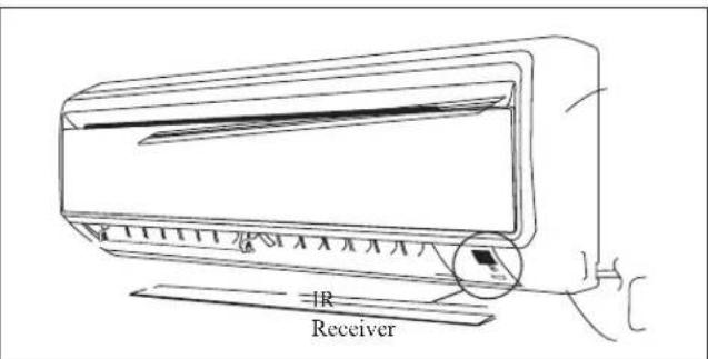
text_image
IR ReceiverCooling Unit/Heat Pump Unit
The table shows the LED indicator lights for the air conditioner unit under normal operation and fault conditions.
The LED indicator lights are located at the side of the air conditioner unit.
The heat pump units are equipped with an “auto” mode sensor whereby it will provide reasonable room temperature by switching automatically to either “cool” or “heat” mode according to the temperature set by the user.
LED Indicator Lights for Cooling Unit/Heat Pump Unit
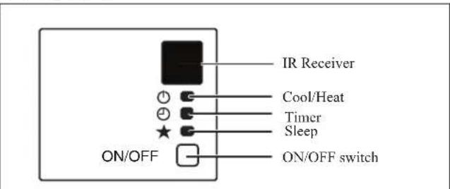
text_image
IR Receiver Cool/Heat Timer Sleep ON/OFF switchLED Indicator Lights: Normal Operation And Fault Conditions For Cooling/Heat Pump Unit
| MV/JX NV Model | ||||
 |  COOL/HEAT(GREEN/RED) COOL/HEAT(GREEN/RED) |  COOL/HEAT(BLUE/RED) COOL/HEAT(BLUE/RED) |  | Operation |
| GREEN | BLUE | Cool mode | ||
| RED | RED | Heat mode | ||
| RED | RED | Auto mode in Heating operation | ||
| GREEN | BLUE | Auto mode in Cooling operation | ||
| ○ | ○ | ○ | Timer on | |
| ○ | ○ | ○ | Sleep mode on | |
| GREEN | BLUE | Fan mode on | ||
| GREEN | BLUE | Dry mode on | ||
| RED | RED | Defrost operation | ||
| GREEN | BLUE | Unit error | ||
ON
① Blinking
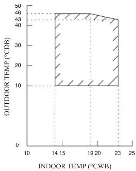
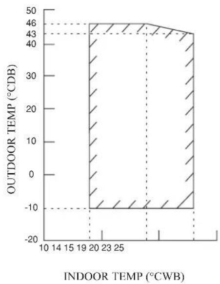
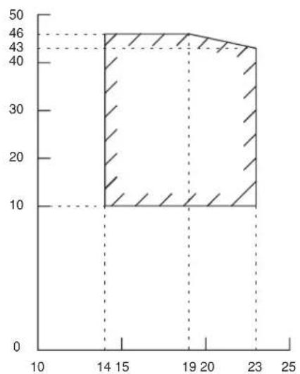
Model: ATXN25/35 ARXN25/35
COOLING HEATING
area
| Indoor Temp (°CWB) | Outdoor Temp (°CDB) | |---|---| | 14 | 46 | | 15 | 43 | | 19 | 46 | | 20 | 43 | | 23 | 43 | The chart displays a single filled area representing the total outdoor temperature range across indoor temperatures from 14 to 23 degrees Celsius. The dashed lines indicate constant outdoor temperature ranges for each indoor temperature interval. No explicit numerical values are provided for the outdoor temperature range.01
area
| Indoor Temp (°CDB) | Outdoor Temp (°CWB) | | ------------------ | ------------------- | | 52 | 10 | | 2015 | 18 |DB: Dry bulb WB: Wet bulb
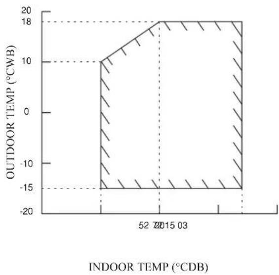
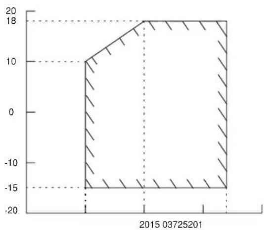
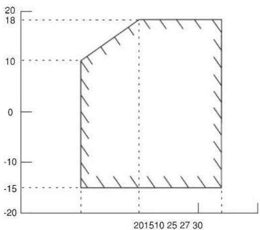
Model: ATXN50/60 ARXN50/60
COOLING HEATING
area
| INDOOR TEMP (°CWB) | OUTDOOR TEMP (°CDB) | |---|---| | 10 | -10 | | 14 | -10 | | 15 | -10 | | 19 | -10 | | 20 | 46 | | 23 | 46 | | 25 | 46 | | 28 | 43 | | 30 | 43 | | 33 | 43 | | 36 | 43 | | 39 | 43 | | 42 | 43 | | 45 | 43 | | 48 | 43 | | 51 | 43 | | 54 | 43 | | 57 | 43 | | 60 | 43 | | 63 | 43 | | 66 | 43 | | 69 | 43 | | 72 | 43 | | 75 | 43 | | 78 | 43 | | 81 | 43 | | 84 | 43 | | 87 | 43 | | 90 | 43 | | 93 | 43 | | 96 | 43 | | 99 | 43 | | 102 | 43 | | 105 | 43 | | 108 | 43 | | 111 | 43 | | 114 | 43 | | 117 | 43 | | 120 | 43 | | 123 | 43 | | 126 | 43 | | 129 | 43 | | 132 | 43 | | 135 | 43 | | 138 | 43 | | 141 | 43 | | 144 | 43 | | 147 | 43 | | 150 | 43 | | 153 | 43 | | 156 | 43 | | 159 | 43 | | 162 | 43 | | 165 | 43 | | 168 | 43 | | 171 | 43 | | 174 | 43 | | 177 | 43 | | 180 | 43 | | 183 | 43 | | 186 | 43 | | 189 | 43 | | 192 | 43 | | 195 | 43 | | 198 | 43 | | 201 | 43 | | 204 | 43 | | 207 | 43 | | 210 | 43 | | 213 | 43 | | 216 | 43 | | 219 | 43 | | 222 | 43 | | 225 | 43 | | 228 | 43 | | 231 | 43 | | 234 | 43 | | 237 | 43 | | 240 | 43 | | 243 | 43 | | 246 | 43 | | 249 | 43 | | 252 | 43 | | 255 | 43 | | 258 | 43 | | 261 | 43 | | 264 | 43 | | 267 | 43 | | 270 | 43 | | 273 | 43 | | 276 | 43 | | 279 | 43 | | 282 | 43 | | 285 | 43 | | 288 | 43 | | 291 | 43 | | 294 | 43 | | 297 | 43 | | 300 | 43 | | Note: The values in the chart are estimated based on the provided code. The data is presented in a single column format. The values are not explicitly labeled in the image. There is no additional data series or legend present in the image. The values are estimated based on the provided code.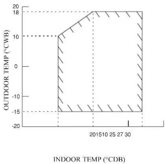
area
| Indoor TEMP (°CDB) | OUTDOOR TEMP (°CWB) | |---|---| | 2015 | 18 | | 30 | -15 | | 40 | 10 | The chart displays a single data series with 'INDOOR TEMP (°CDB)' on the x-axis and 'OUTDOOR TEMP (°CWB)' on the y-axis. The shaded areas represent the range of values for each temperature interval. No trend or correlation is present — this is a static comparison of temperature values across the specified intervals.DB: Dry bulb WB: Wet bulb
AIR FILTER
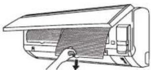
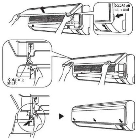
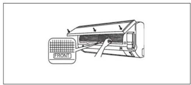
1. Open the front panel.
- Hold the panel at the recesses on the main unit (2 recesses on right and left sides) and lift it until it stops.
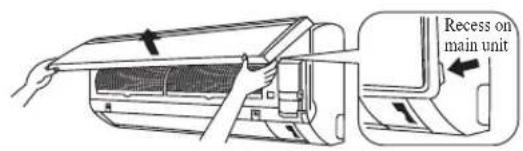
text_image
Recess on main unit2. Pull out the air filters.
- Push a little upwards the tab at the center of each air filter, then pull it down.
3. Take off the Bio filter with bacteriostatic, virustatic functions.
- Hold the recessed parts of the frame and unhook the four claws.
Titanium Apatite Filter (Bio Filter)
Attached Concept
natural_image
Diagram of a car air conditioner unit with a handle and ventilation grille (no text or labels)
text_image
Air Filter Heat exchanger Iso Filter attached part Titanium Apsic Filter4. Clean or replace each filter.
See figure.
- When shaking off remaining water, do not wring the filter.
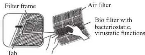
text_image
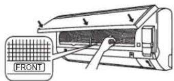
Filter frame Tab Air filter Bio filter with bacteriostatic, virustatic functions5. Set the air filter and Bio filter with bacteriostatic, virustatic functions as they were and close the front panel.
- Insert claws of the filters into slots of the front panel. Close the front panel slowly and push the panel at the 3 points. (1 on each side and 1 in the middle.)
- The air filter and Bio filter with bacteriostatic, virustatic functions have a symmetrical form in the horizontal direction.
text_image
FRONT* Bio Filter and Titanium Apatite Filter are optional accessories.
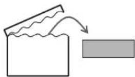
Installation Procedure for Bio Filter
Bio Filter packs in a hermetically-sealed bag.
Take it out at the time of installation.

natural_image
Simple line drawing of a container with wavy lines and an arrow indicating flow or movement (no text or symbols)
Slip the Filter in between Filter frame and Titanium Apatite Filter.
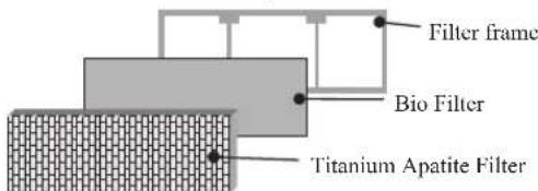
text_image
Filter frame Bio Filter Titanium Apatite FilterCAUTION
- Please use this Bio Filter during dry season such as winter.
• Storage, handling and disposal methods.
• The lifetime of this Bio Filter is about a year after opening.
- In case you do not use this Bio Filter right away, please don't place the Bio Filter in any place where it will be subjected to direct sunlight, high temperatures and/or high humidity.
- There can be slight differences between Bio Filter color because of the manufacturing reasons, there is no effect on the unit performance.
- Please open this bag right before you use it. Bio Filter should remain unopened and sealed in its packaging until right before usage. (It may cause performance deterioration or quality change.)
- To avoid danger of suffocation and any unexpected accident, please dispose the plastic bag immediately after you remove the Bio Filter. Keep out of reach of babies and children.
- If you keep this Bio Filter for a long time, please keep it unopened and store in a cool place avoiding direct sunlight.
- Please dispose the old Bio Filter as nonflammable garbage after use.
• Operation with dirty filters:
(1) cannot deodorize the air. (3) results in poor heating or cooling.
(2) cannot clean the air. (4) may cause odour.
• To order Bio Filter, contact the service shop where you bought the air conditioner.
SERVICE AND MAINTENANCE
Note is valid for Turkey only: The lifetime of our products is ten (10) years
| Service Parts Maintenance Procedures Period | ||
| Indoor air filter | Remove any dust adhering to the filter by using a vacuum cleaner or wash in lukewarm water (below 40°C/104°F) with a neutral cleaning detergent.2. Rinse the filter well and dry before placing it back onto the unit.3. Do not use gasoline, volatile substances or chemicals to clean the filter. | At least once every 2 weeks.More frequently if necessary. |
| Indoor unit Clean | any dirt or dust on the grille or panel by wiping it with a soft cloth soaked in lukewarm water (below 40°C/104°F) and a neutral detergent solution.2. Do not use gasoline, volatile substances or chemicals to clean the indoor unit. | At least once every 2 weeks.More frequently if necessary. |

CAUTION
- Avoid direct contact of any coil treatment cleaners on plastic part. This may cause plastic part to deform as a result of chemical reaction.
1. Open the front panel.
- Hold the panel at the recesses on the main unit (2 recesses on right and left sides) and lift it until it stops.
2. Remove the front panel.
- While lifting the front panel further, slide it to the right and pull it to the front side. The left rotating shaft is detached. Slide the right rotating shaft to the left and pull it to the front side to remove it.
3. Attach the front panel.
- Align the right and left rotating shafts of the front panel with the grooves and push them all the way in.
- Gently close the front panel. (Push both ends and the center on the front panel.)
CAUTION
- Don't touch the metal parts of the indoor unit. It may cause an injury.
- When removing or attaching the front panel, support the panel securely with hand to prevent it from falling.
- For cleaning, do not use hot water above 40^ C, benzine, gasoline, thinner, nor other volatile oils, polishing compound, scrubbing brushes, nor other hand stuff.
• After cleaning, make sure that the front panel is securely fixed.
When The Unit Is Not To Be Used For An Extended Long Period Of Time
| Operate the unit for 2 hours with the following setting.Operating mode : coolTemperature : 30°C/86°F |  | Remove the power plug.If you are using an independent electric circuit for your unit, cut off the circuit.Remove the batteries in the remote control. |  |
TROUBLESHOOTING
For any enquiries on spare part, please contact your authorized dealer. When any malfunction of the air conditioner unit is noted, immediately switch off the power supply to the unit. Check the following fault conditions and causes for some simple troubleshooting tips.
| Fault Causes / Action | |
| 1. Photoconpressins/discountoparting. Waftersafterthminutes conditioner unit is started. | for the compressor to start operating. |
| The air conditioner unit does not operate.2. Power failure, or the fuse needs to be replaced.- The power plug is disconnected.- It is possible that your delay timer has been set incorrectly.- If the fault persist after all these verifications, please contact the air conditioner unit installer. | |
| The air flow is too low.3. The air filter is dirty. | - - The doors or windows are open.- The air suction and discharge are clogged.- The regulated temperature is not high enough. |
| Discharge air flow has bad odour.4. Odours may be caused-by cigarettes, smoke particles, perfume etc. which might have adhered onto the coil. | |
| Condensation on the front air grille of the indoor unit.5. This is caused by air humidity after an extended long period of operation.- The set temperature is too low, increase the temperature setting and operate the unit at high fan speed. | |
| Water flowing out from the air conditioner unit.6. Switch off unit and call dealer.- | |
If the fault persists, please call your local dealer / serviceman.
text_image
L K L Z M Q 3,0 O A U D V B P R Stext_image
C G H E T I J| DimensioniModello | A | B | C | D | E | F | G | H | I | J | K | L | M | N | O |
| 50 NV | 855 | 628 | 328 | 520 | 179 | 46 | 93 | 149 | 101 | 113 | 603 | 126 | 164 | 15 | 34 |
| 60 NV, 50/60 MV | 855 | 730 | 328 | 520 | 179 | 46 | 93 | 149 | 101 | 113 | 603 | 126 | 164 | 15 | 34 |
| DimensioniModello | P | Q | R | S | T | U | V |
| 50 NV | 23 | 362 | 73 | 75 | 8 | 67 | 7 |
| 60 NV, 50/60 MV | 23 | 362 | 73 | 75 | 8 | 67 | 7 |
text_image
Contains fluorinated greenhouse gases R410A ①= kg ②= kg ①+②= kg 6 5 4 1 2 3Inverter (Power Indoor)
Inverter (Power Outdoor)

natural_image
Diagram of a airflow bag with a valve inserted, showing internal mesh structure (no text or symbols)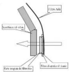
text_image
Fibre Arb Sumbioro il alon Fibre irregat de filminio Fibre di urite il alonnatural_image
Simple line drawing of a document with a paper and a rectangle, no text or symbols present
text_image
L K L Z M Q Z A O D U V B P R S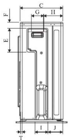
text_image
C G H F E T I J| Abmessung Modell | A | B | C | D | E | F | G | H | I | J | K | L | M | N | O |
| 50 NV | 855 | 628 | 328 | 520 | 179 | 46 | 93 | 149 | 101 | 113 | 603 | 126 | 164 | 15 | 34 |
| 60 NV, 50/60 MV | 855 | 730 | 328 | 520 | 179 | 46 | 93 | 149 | 101 | 113 | 603 | 126 | 164 | 15 | 34 |
| Abmessung Modell | P | Q | R | S | T | U | V |
| 50 NV | 23 | 362 | 73 | 75 | 8 | 67 | 7 |
| 60 NV, 50/60 MV | 23 | 362 | 73 | 75 | 8 | 67 | 7 |
INSTALLATIONSHANDBUCH
(1) GWP = Treibhauspotential
text_image
Contains fluorinated greenhouse gases R410A ①= kg ②= kg ①+②= kg 6 5 4 1 2 3Inverter (Power Outdoor)
natural_image
Diagram of a airflow system inside a fan or duct (no text or symbols)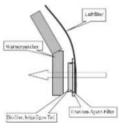
natural_image
Simple line drawing of a container with wavy top and arrow indicating flow, next to a gray rectangle (no text or symbols)
text_image
L K L M Q 3,0 A Z D U V B P R S Ztext_image
C F G H E * I J T| Modelo\Dimensión | A | B | C | D | E | F | G | H | I | J | K | L | M | N | O |
| 50 NV | 855 | 628 | 328 | 520 | 179 | 46 | 93 | 149 | 101 | 113 | 603 | 126 | 164 | 15 | 34 |
| 60 NV, 50/60 MV | 855 | 730 | 328 | 520 | 179 | 46 | 93 | 149 | 101 | 113 | 603 | 126 | 164 | 15 | 34 |
| Modelo\Dimensión | P | Q | R | S | T | U | V |
| 50 NV | 23 | 362 | 73 | 75 | 8 | 67 | 7 |
| 60 NV, 50/60 MV | 23 | 362 | 73 | 75 | 8 | 67 | 7 |
text_image
Contains fluorinated greenhouse gases R410A ①=kg ②=kg ①+②=kg 6 5 3Inversor (Outdoor Power)
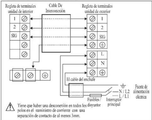
flowchart
graph TD
    A["Regleta de terminales unidad de interior"] --> B["Cable De Interconexión"]
    B --> C["Regleta de terminales unidad de exterior"]
    B --> D["El cable del enchufe"]
    D --> E["Fusibles / interruptor principal"]
    E --> F["N / L2"]
    E --> G["L / L1"]
    E --> H["Fluente de alimentación eléctrica"]
    style A fill:#f9f,stroke:#333
    style B fill:#ccf,stroke:#333
    style C fill:#cfc,stroke:#333
    style D fill:#fcc,stroke:#333
    style E fill:#cff,stroke:#333
    style F fill:#ffc,stroke:#333
    style G fill:#ffc,stroke:#333
    style H fill:#ffc,stroke:#333
    note right of A: Tiene que haber una desconexión en todos los disyuntor polos en el suministro de corriente con una separación de contacto de al menos 3mm.
natural_image
Diagram of a car air conditioner unit with a handle and ventilation grille (no text or labels)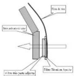
text_image
Fibro kiln Fibro kiln parte adjunta Fibro Titanium Apulsarnatural_image
Simple line drawing of a container with wavy lines and an arrow indicating flow or movement (no text or symbols)
text_image
L K L Z M Q 3,0 A U O D V B P S Rtext_image
F E C G H T I J| Dimension Modèle | A | B | C | D | E | F | G | H | I | J | K | L | M | N | O |
| 50 NV | 855 | 628 | 328 | 520 | 179 | 46 | 93 | 149 | 101 | 113 | 603 | 126 | 164 | 15 | 34 |
| 60 NV, 50/60 MV | 855 | 730 | 328 | 520 | 179 | 46 | 93 | 149 | 101 | 113 | 603 | 126 | 164 | 15 | 34 |
| Dimension Modèle | P | Q | R | S | T | U | V |
| 50 NV | 23 | 362 | 73 | 75 | 8 | 67 | 7 |
| 60 NV, 50/60 MV | 23 | 362 | 73 | 75 | 8 | 67 | 7 |
MANUEL D'INSTALLATION
text_image
Contains fluorinated greenhouse gases R410A ①= kg ②= kg ①+②= kg 6 5 4 1 2 3| Tuyau, mm (pouce) Couple, Nm / (ft-lb) | |
| 6,35 (1/4") 18 (13,3) | |
| 9,52 (3/8") 42 (31,0) | |
| 12,70 (1/2") 55 (40,6) | |
| 15,88 (5/8") 65 (48,0) | |
| 19,05 (3/4") 78 (57,6) | |
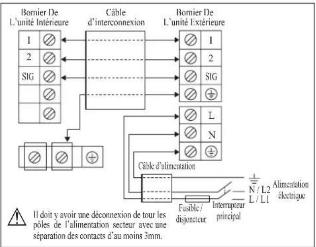
Inverter (Power Outdoor)
flowchart
graph TD
    A["Bornier De L'unité Intérieure"] --> B["Câble d'interconnexion"]
    C["SIG"] --> B
    D["..."] --> B
    E["..."] --> B
    F["..."] --> B
    G["..."] --> B
    H["..."] --> B
    I["..."] --> B
    J["..."] --> B
    K["..."] --> B
    L["..."] --> M["Câble d'alimentation"]
    N["..."] --> M
    O["..."] --> M
    P["..."] --> M
    Q["..."] --> M
    R["..."] --> M
    S["..."] --> M
    T["..."] --> M
    U["..."] --> M
    V["..."] --> M
    W["..."] --> M
    X["..."] --> M
    Y["..."] --> M
    Z["..."] --> M
    AA["..."] --> M
    AB["..."] --> M
    AC["..."] --> M
    AD["..."] --> M
    AE["..."] --> M
    AF["..."] --> M
    AG["..."] --> M
    AH["..."] --> M
    AI["..."] --> M
    AJ["..."] --> M
    AK["..."] --> M
    AL["..."] --> M
    AM["..."] --> M
    AN["..."] --> M
    AO["..."] --> M
    AP["..."] --> M
    AQ["..."] --> M
    AR["..."] --> M
    AS["..."] --> M
    AT["..."] --> M
    AU["..."] --> M
    AV["..."] --> M
    AW["..."] --> M
    AX["..."] --> M
    AY["1"] & AZ["2"] & BA["SIG"] & BB["L"] & BC["N"] & BD["L/L1"] & BE["N/L2"] & BF["Alimentation électrique"] & BG["Interrupteur principal"] & BH["Fusible/disjoncteur"]
Ainsi, Charge additionnelle = 4,5[m] x 20[g/m]
$$ = 9 0, 0 [ \mathrm{g} ] $$
L'INDICATEUR S'ALLUME
natural_image
Diagram of a car air conditioner unit with a handle and ventilation grille (no text or symbols)
text_image
Film coat film thickness color Film thickness: Film Be Film insulation: Epicatenatural_image
Simple line drawing of a document with wavy lines and an arrow, next to a gray rectangle (no text or symbols)
text_image
Contains fluorinated greenhouse gases R410A ①= kg ②= kg ①+②= kg 6 5 4 1 2 3natural_image
Diagram of a car air conditioner unit with airflow path and ventilation cover (no text or labels)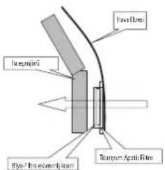
text_image
Heat flows Temperature Bypass the element beam Temperature Apatic fibretext_image
Contains fluorinated greenhouse gases R410A ①=kg ②=kg ①+②=kg 6 5 3text_image
Technical diagram showing internal components of a device with labeled parts and directional arrows indicating flow or movement.text_image
Air Condition is CURRENT ON DOKS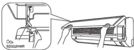
natural_image
Technical illustration of a mechanical component before and after assembly (no text or symbols)
ОСТОРОЖНО
RXN50MV1B, RXN60MV1B, ARXN50MV1B, ARXN60MV1B,
RXN50NV1B, RXN60NV1B, ARXN50NV1B, ARXN60NV1B, RXB50CV1B, RXB60CV1B, ARXB50CV1B, ARXB60CV1B,
ARXN50MV1B7, ARXN60MV1B7, RXK50AV1B, RXK60AV1B,
01 Directives, as amended.
02 Drakiven, gemäß Änderung. 03 Drakives, jeles rua modifies.
Ostend, 09th of December 2014
text_image
DAIKIN Shigeki Morita Director Ostend, 09th of December 2014 DAIKIN EUROPE N.V. Zandvoordestraat 300, B-8400 Oostende, BelgiumSLY-C V3
| CE - DECLARATION-OF-CONFORMITY | CE - DECLARACION-DE-CONFORMIDAD | CE - DECLARAÇÃO-DE-CONFORMIDADE | CE - ERKLÆRING OM-SAMSVAR | CE - IZJAVA-O-USKLADENOSTI | CE - IZJAVA O SKLADNOSTI | CE - ATITIKTIES-DEKLARACJIA |
| CE - KONFORMITATSERKLARUNG | CE - DICHIARAZIONE-DI-CONFORMITA | CE - ЗАЯВЛЕНИЕ-O-COOTBETСТВИИ | CE - ILMOITUS-YHĐENMUKAISUUDESTA | CE - MEGFELELOSEGI-NYILATKOZAT | CE - VASTAVUSDEKLARATSIÖON | CE - ATBILSTIBAS-DEKLARACJIA |
| CE - DECLARATION-DE-CONFORMITE | CE - ΔΗΛΩΣΗ ΣΥΜΜΟΡΦΩΣΗΣ | CE - OVERENSSTEMMELSESERKLÆRING | CE - PROHLÁŠENÍ-O-SHODĚ | CE - DEKLARACJA-ZGODNOŠCI | CE - ДЕКЛАРАЦИЯ-ЗА-СЪОТВЕТСТВИЕ | CE - VYHLÁSENIE-ZHODY |
| CE - CONFORMITEITSVERKLARING | CE - FÓRSÄKRAŃ-OM-ÖVERENSTÄMMELSE | CE - DECLARAȚIE-DE-CONFORMITATE | CE - UYUMLULUK-BILDIRIŠI |
Daikin Europe N.V.
RXN25MV1B, RXN35MV1B, ARXN25MV1B, ARXN35MV1B,
RXN25MV1B7, RXN35MV1B7, ARXN25MV1B7, ARXN35MV1B7
RXN25NV1B, RXN35NV1B, ARXN25NV1B, ARXN35NV1B, RXK25AV1B, RXK35AV1B.
| 01are in conformity with the following standard(s) or other normative document(s), provided that these are used in accordance with our instructions: | 08estão em conformidade com a(s) seguinte(s) norma(s) ou outro(s) documento(s) normativo(s), desce que estes sejam utilizados de acordo com as rossas instruções: | 16megteleren az alaboi szabányloknak vagy egyéb ríanyacó dokumentumloknak, na szokat előirás szerint hasznáják: |
| 02dorben folgender Nom(n) oder einem anderen Normdokument oder-dokumenten entspricht/ontsprachien, unter dar Voraussolung, da/s sig gemäß unseren Anweisungen eingesetzt werden: | 09contrate企业和 condujuem standartam eller fundim normativemn documentan, por условii an использования согласно налики инструкции: | 17soelnaya wymogi nastepujajych norm i innych dokumente normalizacyjnych, pod warunkient ze używane sa zgodnie z naszymi instrukcijami: |
| 03sort de folgende à lauxe norme(s) ou autre(s) document(s) normati(s), pour autant quils soient utilisés conformément à noe instructions: | 10overholder folgende standard(er) eller andet'andere retningsgivende dokumenter), forudsat at disse anvendes i herhold tl vore instrukser: | 18sunt in conformitate cu umátorul (urmátoare) standard(c) sau all(t) document(e) normativ(e), cu condiça ca acestea să fite utilizate in conformitate cu instrucțiun noastre: |
| 04conform de volgende norm(n) of één of meer andere bindende documenten zijn, op voorwaarde dat ze worden gebrukt overeenkomstig onze instructies: | 11respektive utrusting ár utförd i överensstármelse med och följer följande standard(er) eller andra normgivande document under fortusättning att användning sker i överensstármelse med vára instruktioner: | 19sidin z nasletnjini standardi in drugimi normativi, pod pogjem, da se uporabijajo v svladu z našni navodii: |
| 05están en conformidad con la(s) siguiente(s) norma(s) u otro(s) documento(s) normativo(s), siempre que sean utilizados de acuerdo con rous/as instruciodes: | 12respektiva utlyr ar i overensstármelse med folgende standard(er) eller andre normgivende documenter), under fortusselming av at disse brukes i merhoid tl vare instrukser: | 20or vastavuses járgame(te standardit)ega vii leiste normativeste documentedge, kui red kasautakse vastavat mele junenditele: |
| 06scomo conformi all(t) seguente(s) standard(s) o alto(t); documento(t) a carattare normalivo, a palla che varvano usati in conformità alle instruktiones: | 13vastaavat seuraavien standarden ja muden ohjeellisten dokumentien vastimuksa edellytäen, että nită käyletään ohjeidenme nukaisesti: | 21suotaestaat na cnednite standardi miri diurni normativi dokuerni, pri yocene, ve ce naorostat currocho-vašete instruksioni: |
| 07čiva oðupwova με to(t) oðúkoubo(a) mpórumo(a) í čilo éyvspor(o) kovovopuv, unó tvy spořiměcení óri yanouomotoćvins oúquwva με ης obývejs με: | 14za predokladu, že jsou využívány v souladu s našimi pokyny, odpovidaji nasledujícim normárn nebo normativnim dokumentum: | 22allinka zemiau nurodylus standardus ir (arba) kilus nominius dokumentus su sayga, kad ya naojomi pagai mõsú nurodymus: |
| 23lad. ja listoli abvislasi nažolja noradjumiem, abvisl sakojisem standartium un citiem normativiem documentiem: | ||
| 24su za v zhođe na nasledovmu(ými) normoutami alebo hými(i) normativmý(i) dokumentomami), za depobkadu, že sa použireju v svilade s našim távodom: |
[Non-Text]
EN60335-2-40
| 01 Directives, as amended. | 10 Direktiver, med senere sendinger. | 19Directive z vserni sorenembami. |
| 02 Direktiven, gemäß Änderung. | 11 Direktiv, med foretagna äncoringar. | 20Directiv do koos muudatustaga. |
| 03 Directives, lettes que modifiées. | 12 Direktiver, med fontalle endringer. | 21Direktivs, c tennite ümeneñeria. |
| 04 Richtlijnen, zoals geamendaard. | 13Dradivvá, sallasna kun na oval muutarijuna. | 22Direktivse su paclcyrnas. |
| 05 Directives, según lo emrendado. | 14ov oalnim zreni. | 23Direktivs un lo paclidirajurno. |
| 06 Directive, come da modifica. | 15Smijerica, kako je izmijeryena. | 24Smirecia, v platom zreni. |
| 07 Cönyvův, ómów čýouy račstomponjd. | 16 rányvelek) és mõcoteitbasak rendekezëset | 25Değstilniis halertyle Yönetrelikter. |
| 08 Directives, conforme alteração em. | 17 z pólzniejszymi poprawkami. | |
| 09 Direktive se всеми поправками. | 18Directivelor cu amendamentele respective. |
Ostend, 09th of December 2014
FTXN25MV1B,FTXN35MV1B,FTXN50MV1B,FTXN60MV1B,ATXN25MV1B,ATXN35MV1B,ATXN50MV1B,ATXN60MV1B,FTXN25NV1B,FTXN35NV1B,FTXN50NV1B,FTXN60NV1B,ATXN25NV1B,ATXN35NV1B,ATXN50NV1B,ATXN60NV1B
FTXK25AV1BS, FTXK35AV1BS, FTXK50AV1BS, FTXK60AV1BS, FTXK25AV1BW, FTXK35AV1BW, FTXK50AV1BW, FTXK60AV1BW, FTXB50CV1B, FTXB60CV1B, ATXB50CV1B, ATXB60CV1B.
| 01 are in conformity with the following standard(s) or other normative document(s), provided that these are used in accordance with our instructions: | 08 esto em conformidade com a(s) segunte(s) noma(s) ou outro(s) documento(s) normativo(s), desde que estes seiam utilizados de acordo com as nossas instruções: | 16 megfelenek az abioi szabvány(cknak) vagy egyéb irdyadó dokumentura(cknak, ha azokat elitris szerint használják: |
| 02 donden folgenden Normen(s) oder einem anderen Nomendokument oder dokumentan entspricht/lonisnechen, unter der Vorassatzung, daß sie gemäß unseren Anweisungen üngesetzt worden: | 09 coconestactoust stevruijami standardam iimi другim normativemik documentam, pri uvozami ik использования согласно нацим instructurans: | 17 spernaje wyrnog nastepujáçych nom i innych documentów normalizacyjnych, pod warunviem ze używane są zgodnie z naszymi instructurans: |
| 03 sont conformos à lataux normos(s) ou auto(s) document(s) normati(s), pour autant qu'le solenti utilisás conformément à nos instructions: | 10 overhelder folgende standarder(s) alter ander/cmde relningsgivende dokument(er), lorudsal at disse anvendos i hormid lii vare instrukser: | 18 sunt in conformitate cu umárionu (umálcards) standard(s) sau all(e) document(e) normativ(e), cu condite sa acustice sá file utilizate in conformitate cu instructurile roastre: |
| 04 conforme do voigante normen(s) of átor of inner andere bihenda documenten zijn, op voorwaarde dal ze worden gebruikt overankomstig orze instructures: | 11 respektive utrustning ár utförd i överensstärmelse med och följer följande standard(er), eller andra normgivande dokument, under förutsättning alt användring sker i överensstärmelse med våra instruktioner: | 19 skladni z nastelnjimi standardi in drugimi normativ, pod pogojem, da sa uporabljajo v skladu z našmi rnavodli: |
| 05 estar en conformidad con la(s) siguiente(s); norma(s) u otro(s) documento(s) normativo(s), s empre que sean utilizados de acuerdo con nuestras instrucciones: | 12 raspektive utsiy er i overensstärmelse med folgende standard(er) alter andre normgivande dokument(er), undar forusselting av al disse brukes; hanhold li váno instrukser: | 20 sonstavasta sa следmitte standardi iimi другi normativne dokumente, pri uvozeme. Ve se omkoozat cylosno najshite instrukteries: |
| 06 som conformii a(i) seguente(s) standard(s) o altro(s) documento(s) a carallera normativo, a patlo cha vengano usali in conformità alla nostra istruzione: | 13 vastavaat souraivan standardari ja muden ohecellison dokumentien vastinuksia odelylläen, etla nilà käyteliäin oheidenme muksesti: | 21 allinka žemnau nurodylas standartus in (arora)klus norminus documentus su salyga, kad yra naudojami pagal mčay, nurodymus: |
| 07 ľiva strupovu ve tu (o)s okkoubejo (p) projumo(o) i šklo čyropogo(o) kovovistujów, umto tvny proumětićom ári yorju moportovu svúpuwo με τις obýtíc μος | 14 za predovíduo, že jsou využívány v souedu s natími pokyny, odpovídaj nasledujícím normám nebo normativim dokumentím: | 22 lad, ja lototí ablítási ražalja noráčjumi, elbitá sakopšiem standartium un ciliam normativem dokumentiam: |
| 15 u skladu sa sliedacmi standartom(ma) i li drugim normativim dokumentam(ma), uz uyej da ss on koriste u skladu s našim uputama: | 24 su v zrode s nasledovnu(yni) nomrou(ami) alebo ným(i) normativvry(i) dokumentom(ami), za prodovídu, že sa použivá u svlade s našim návodom: | |
| 25 útinčn, malmatanmiza göre kullanimasi kosulyla sjařadáce standardier ve norm belirten bejelerle uyuntodur: |
EN60335-2-40,
| 01 following the provisions of: | 10 under iagtlageise af bestermalsente i: | 19 ob upstalvarju dotob | 01 Dractives, as amended. | 10 Draktiver, ned sanera andringer. | 19 Draktive z vseri spramenbani. |
| 02 gemäß den Vorschniller dar | 11 enigt vilkoran i: | 20 vastavall rüneleska: | 02 Draktiven, gemäß Änderung. | 11 Draktiv, ned foretagna ändringar. | 10 Draktivid kras moudaluslega. |
| 03 conformément aux stipulations des: | 12 gt. henhold til bestermelsene i: | 21 spodaatki naayata na: | 03 Dractives, telles que modifiées. | 12 Draktiver, ned foretate enringer. | 21 Spontekik, staksama komanihnia. |
| 04 overeenkomstig de opalingen van: | 13 noudastaen määräksia: | 22 lakantis nuostaju paleikamu: | 04 Richtljen, zoals geamendeerd. | 13 Deriktiva, selatsina qui ne ovat muutettuina. | 22 Direktyvose su papildymais. |
| 05 seguendo las dispositions de: | 14 za dodrženi ustanoveni pledpisu: | 23 levroor orasibas, kas noteiklas: | 05 Dractivas, segan le emmendado. | 14 v platrém zónří. | 23 Direktivas un to papildinajmos. |
| 06 secondo le prescrizioni per: | 15 prema oredbanu: | 24 odrzanačić ustanovenia: | 06 Drattive, come da modifica. | 15 Smerince, kako je izmjerjeno. | 24 Smernice, v platnom znení. |
| 07 με rýpynov nuv žimotávou tuw: | 16 kőveti a/c): | 25 burun kosulianna aygun ośrak: | 07 Ožnýdav, čtuv čtuvy pomomtoráci. | 16 Iranyelvsk) és módostásak rondelkazeseit. | 25 Degistrimis hallaryla Yönelmatikler. |
| 08 de acordo com o previsto em: | 17 zgodnie z postanowieniani Dyreklyw. | 08 Dractivas, conforme alleração em. | 17 z pozmjeszym poprawkami. | ||
| 09 a contrastivity s posponkenniam: | 18 in arma pravedinter: | 09 Drerkrats co svemni popravkami. | 18 Dracterior, cu amancenentele respective. |
| 01 Note * | as set cut in <A> and judged positively by <B> according to the Certificate <C> | 06 Nota * | desinato nel <A> e glucicato positivamente da <B> secondo i Certificate <C> | 11 Information * | enligt <A> och godiatis av <B>enligt. Certifikatet <C> | 16 Meglagyzés * | a(j) <A> aiejän, a(j) <B> igazita a meglelebėti, a(j) <C> tanistitvianyszerint. | 21 3aßenekwa * | * parte a kontsídno e <A> i očenėno nepokojatnio ot<B> caylaso-Čeřníkříkatta <C> |
| 02 Hinweis * | wie in <A> aufgeführt und von <B>positiv beurteil gemat Zertifikat <C> | 07 Šnpišiwnog * | ómyk kotopičtro stro <A> ka kalivtal běmíd stro ro <B>požupovsku je ro Īpostotobrýkô <C> | 12 Merk * | som del fremkommeri <A>og glenom positiv bodanmelise ay <B>laiga Sertifikat <C> | 17 Uwaga * | zgodne z odkumentace <A>, pozytywną oprinia <B> Šwiladectwem <C> | 22 Pastaba * | kaip nustalyta <A> ir kap beligamai ruspresta <B> paga Sertifikat <C> |
| 03 Remarque * | tel que odefin cans <A>ed' évané positivement par <B> conformément au Certificat <C> | 08 Nota * | tal como estabsecce em <A> e com o sarcor positivo de <B> de acorc o com<Certificado <C> | 13 Huom * | jolka on esltityl aslakijasa <A> je jolna <B> on nyväksyset/Sertifikaitin <C> mukasesti. | 19 Nota * | aşya cum este steatit in <A>si acrediat pozítv de <B> In conformitate cu Certificatul <C> | 23 Piežimas * | ká načetás <A> un analstot <B> poztikejam vērtiumam seskraj arseriftikatu <C> |
| 04 Bemerk * | zaas vermeld in <A>en positief beconceeld door <B> evereenkomstig Certificaat <C> | 09 Prinkněchniņie * | kak uvažana ve <A> ne coontacteniņie o poskonsitelysni pečleniem <B> oslačas-c | 14 Poznámka * | jak bylo uvedeno v <A> a pozitivná žištāno <B> v souladu s osvědčanim <C> | 19 Opomba * | koj je določenov v <A> in odobreno s strani <B> v skoulu s certifikatom <C> | 24 Poznámka * | ako bolo uvedené <A> a poztivně zisteně <B> v sūlāce s osvědčanim <C> |
| 05 Nota * | como se establece en <A> y as valorao positivamente por <B> de acuendu con el Certificado <C> | 10 Bemark * | Sanskndelstey <B> som anfert <A> og positiv vuderast a <B> I therhold tl Certifikat <C> | 15 Napomena * | sakoj je izloženo ur <A> i pozitivno ocijeneno od strane <B>prema Certifikatu <C> | 20 Márkus * | nagu on nádalud dokumendás <A> ja heaks kidatud <B> jāgi vastavili sertifikacille <C> | 25 Not * | ta telníklígji gbi već <B> tafirlandan olumu, clarak cegeferndir klígi gbi. |
| < A > OYLR&D-054-EMC | |
| <B> | INTERTEK SEMKO AB(NB0413) |
| <C> | 903234T1 / 12-2014 |

Shigeki Morita
Director
Ostend, 09th of December 2014
DAIKIN EUROPE N.V.
P.O.Box 18674, Galleries 4, 11th Floor, Downtown Jebel Ali, Dubai, UAE.
DAIKIN INDUSTRIES, LTD.
Head office:
Umeda Center Bldg., 2-4-12, Nakazaki-Nishi, Kita-ku, Osaka, 530-8323 Japan
Tokyo offi ce:
JR Shinagawa East Bldg., 2-18-1, Konan,
Minato-ku, Tokyo, 108-0075 Japan
http://www.daikin.com/global/
Head office:
Umeda Center Bldg., 2-4-12, Nakazaki-Nishi, Kita-ku, Osaka, 530-8323 Japan
Tokyo office:
JR Shinagawa East Bldg., 2-18-1, Konan,
Minato-ku, Tokyo, 108-0075 Japan
http://www.daikin.com/global/
P.O.Box 18674, Galleries 4, 11th Floor,
Downtown Jebel Ali, Dubai, UAE.
Importer for Turkey
text_image
Diagram illustrating the process of air conditioner installation steps, showing hand positioning and component disassembly.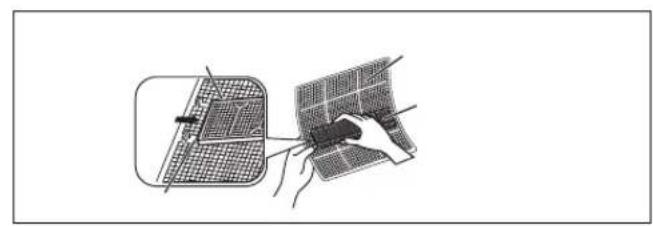
natural_image
Illustration of two hands using a tool to adjust a grid-patterned panel (no text or symbols visible)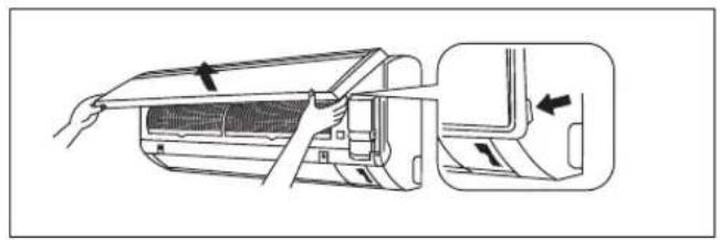
natural_image
Diagram showing airflow or ventilation process of an air conditioner unit, with no text or symbols present.5
natural_image
Line drawing of a car air conditioner unit with front panel and control panel (no text or symbols)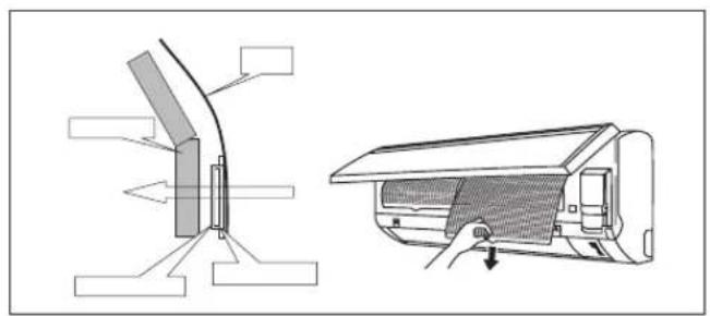
text_image
Technical diagram showing airflow or ventilation system with labeled components and directional arrows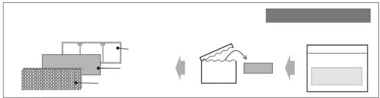
flowchart
graph LR
    A["Brick Wall"] --> B["Material Handling"]
    B --> C["Recycling Waste"]
    C --> D["Finished Product"]

natural_image
Blank white image with three small black dots in the bottom-right corner (no text or symbols)ARXN25/35
area
| Date | Value | | ---------- | ----- | | 2015 03725201 | -15 | | 2015 03725201 | 18 |(°CDB)
area
| X-Axis | Y-Axis | |---|---| | 14 | 46 | | 15 | 46 | | 19 | 46 | | 20 | 46 | | 23 | 43 | | 25 | 43 |ARXN50/60
area
| Time | Value | | ---- | ----- | | 201510 | 18 | | 25 | 18 | | 27 | 18 | | 30 | -15 |
area
| X-Axis | Y-Axis | |---|---| | 10 | 46 | | 14 | 43 | | 15 | 43 | | 19 | 43 | | 20 | -10 | | 23 | -10 | | 25 | -10 | | 27 | -10 | | 28 | -10 | | 29 | -10 | | 30 | -10 | | 31 | -10 | | 32 | -10 | | 33 | -10 | | 34 | -10 | | 35 | -10 | | 36 | -10 | | 37 | -10 | | 38 | -10 | | 39 | -10 | | 40 | -10 | | 41 | -10 | | 42 | -10 | | 43 | -10 | | 44 | -10 | | 45 | -10 | | 46 | -10 | | 47 | -10 | | 48 | -10 | | 49 | -10 | | 50 | -10 | | 51 | -10 | | 52 | -10 | | 53 | -10 | | 54 | -10 | | 55 | -10 | | 56 | -10 | | 57 | -10 | | 58 | -10 | | 59 | -10 | | 60 | -10 | | 61 | -10 | | 62 | -10 | | 63 | -10 | | 64 | -10 | | 65 | -10 | | 66 | -10 | | 67 | -10 | | 68 | -10 | | 69 | -10 | | 70 | -10 | | 71 | -10 | | 72 | -10 | | 73 | -10 | | 74 | -10 | | 75 | -10 | | 76 | -10 | | 77 | -10 | | 78 | -10 | | 79 | -10 | | 80 | -10 | | 81 | -10 | | 82 | -10 | | 83 | -10 | | 84 | -10 | | 85 | -10 | | 86 | -10 | | 87 | -10 | | 88 | -10 | | 89 | -10 | | 90 | -10 | | 91 | -10 | | 92 | -10 | | 93 | -10 | | 94 | -10 | | 95 | -10 | | 96 | -10 | | 97 | -10 | | 98 | -10 | | 99 | -10 | | 100 | -10 | The chart displays a single data series with values for each data point. The x-axis ranges from '10' to '25' and the y-axis ranges from '46' to '43'. There are no labels or additional data series in this view.الشحن الاضافي
text_image
IR most quicknatural_image
Technical drawing of a mechanical assembly with bolted joint and fastener (no text or symbols)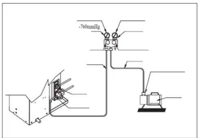
text_image
-760mmHg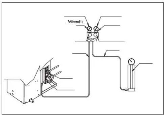
text_image
-760mmHg**
| 25355060 (ATXN) | ||||
| 25355060 (ARXN) | ||||
| 220-240V/~/50Hz+ | ** | |||
| 2.53 | 1.53 | 2* | ||
| 2.54 | 1.54 | 2* | ||
| 20 | 16 | A | ||
flowchart
graph TD
    A["Switch 1"] --> B["Switch 2"]
    C["Switch N"] --> D["Switch L"]
    E["Load L/L1"] --> F["Load N/L2"]
    G["Load N/L2"] --> H["Ground"]
    I["SIG"] --> J["SIG"]
    K["Ground Symbol"] --> L["Warning symbol"]
text_image
Technical diagram showing electrical wiring connections into a device with labeled components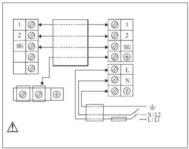
flowchart
graph TD
    A["1"] --> B["2"]
    B --> C["SIG"]
    C --> D["3"]
    D --> E["4"]
    E --> F["5"]
    F --> G["L"]
    G --> H["N"]
    H --> I["6"]
    I --> J["7"]
    J --> K["8"]
    K --> L["9"]
    L --> M["10"]
    M --> N["11"]
    N --> O["12"]
    O --> P["13"]
    P --> Q["14"]
    Q --> R["15"]
    R --> S["16"]
    S --> T["17"]
    T --> U["18"]
    U --> V["19"]
    V --> W["20"]
    W --> X["21"]
    X --> Y["22"]
    Y --> Z["23"]
natural_image
Simple line drawing of a pipe fitting with a circular end cap and two arrows indicating direction (no text or symbols)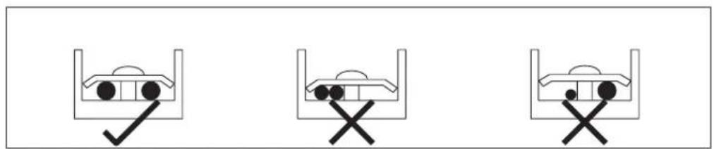
natural_image
Three identical diagrams showing a container with circular ends and a checkmark, each marked with an 'X' symbol (no text or labels present)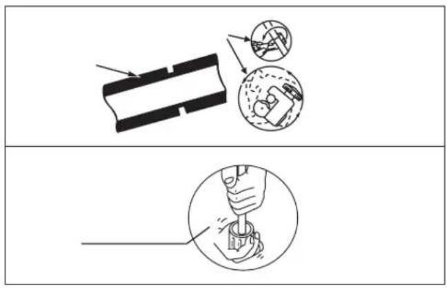
text_image
Technical diagram illustrating a mechanical assembly process with labeled components and a magnified view of the tool tip.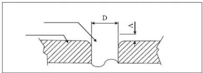
text_image
D A| 1/4"6.3 | |||
| 3/8"9.5 | |||
| 1/2"12 | |||
| 5/8"15 | |||
| 3/4"19 | |||
text_image
Technical diagram illustrating three-step mechanical assembly steps: tool, screw, and wrench with directional arrows indicating motion.| 6.35 (1/4")18 (13.3) | |
| 9.52 (3/8")42 (31.0) | |
| 12.70 (1/2") 55 (40.6) | |
| 15.88 (5/8") 65 (48.0) | |
| 19.05 (3/4") 78 (57.6) |
text_image
Technical diagram of an air conditioner system with labeled dimensions L and E, showing airflow path and fan component.| 25355060 | ||||
| 3 | 3 | |||
| 30 | 20 | |||
| 10 | 10 | |||
| 9.52 (3/8")12.70 (1/2")15.88 (5/8") | ||||
| 6.35 (1/4")6.35 (1/4") | ||||
| 1.3 | 0.18 | |
| 1.5 | 0.20 | 1/2" (OD12.7) |
| 2 | 0.25 | 5/8" (OD15.9) |
| 2.4 | 0.35 | 3/4" (OD19.1) |
| 3 | 0.40 | 7/8" (OD22.2) |
| 3.4 | 0.45 | 1" (OD25.4) |
| 3.7 | 0.50 | 1 1/8" (OD28.6) |
| 4.4 | 0.60 | 1 3/8" (OD34.9) |
natural_image
Technical line drawing of a mechanical component with no visible text or symbols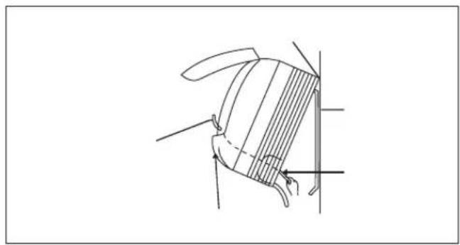
natural_image
Technical line drawing of a mechanical component with no visible text or symbols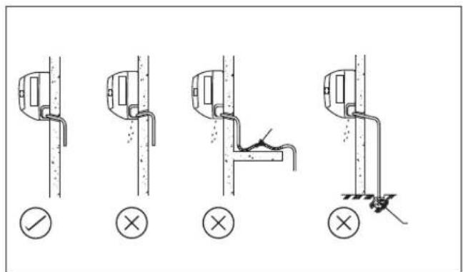
text_image
Technical diagram showing four different installation methods for a wall fixture, with check and cross symbols indicating inspection or testing conditions.
text_image
!
text_image
20/35 166 184 42.2 288 25.9 54.5 153.8 263 51.9 800 181.7 35.5 45.9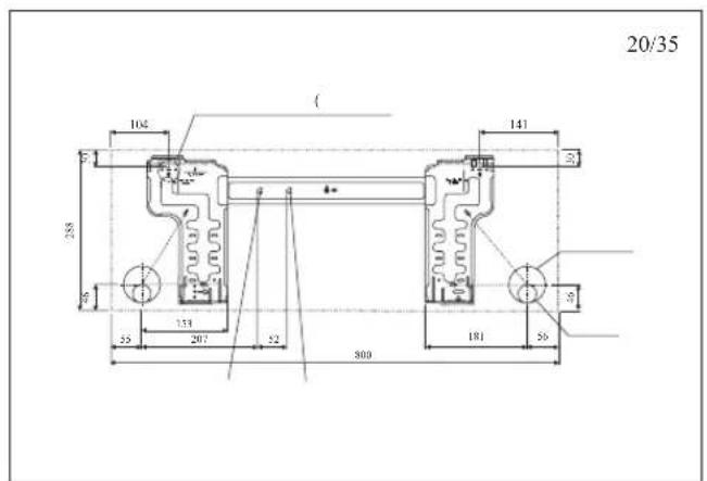
text_image
20/35 104 ( ) 141 288 133 207 52 500 181 56 9 9 9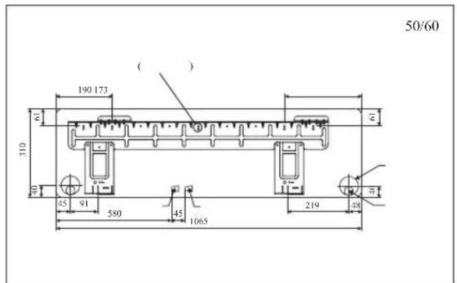
text_image
50/60 190 173 ( ) 61 310 40 45 91 580 45 1065 219 48 41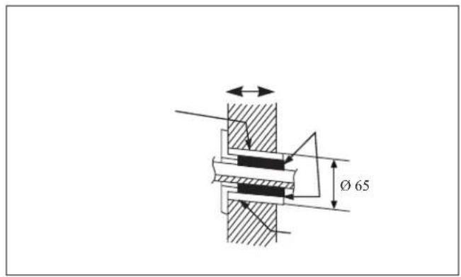
text_image
Ø 65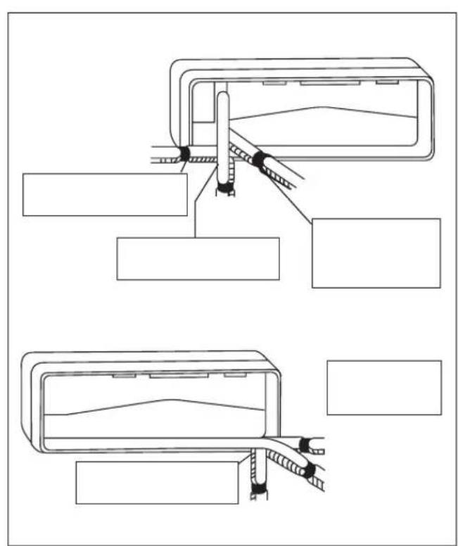
natural_image
Technical line drawing of a mechanical assembly with two views (top and side), showing components like a bracket, guide rails, and clamps (no text or symbols)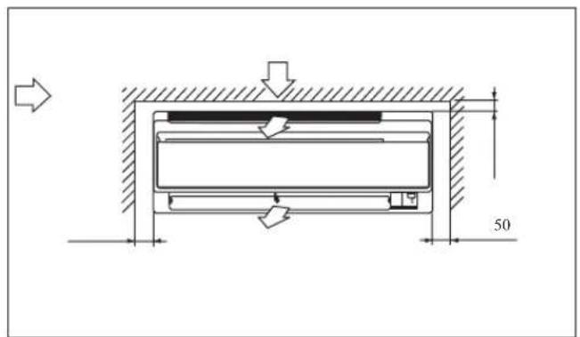
text_image
Technical diagram showing a mechanical or structural component with dimension annotations and directional arrow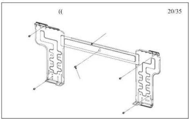
text_image
(20/35)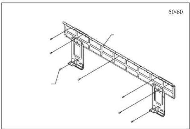
text_image
50/60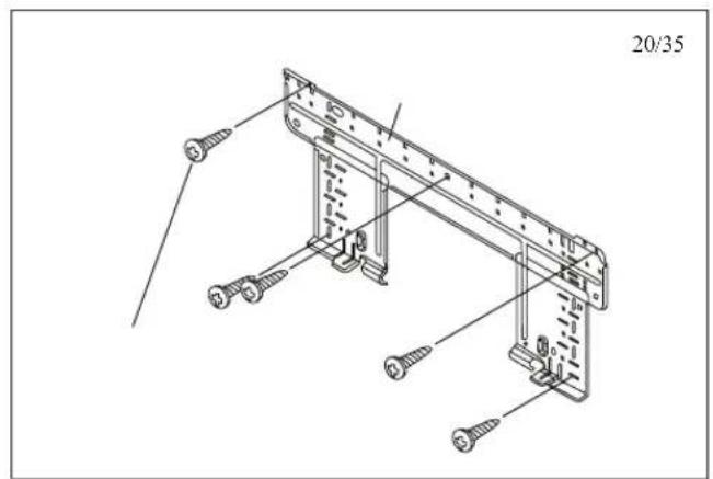
text_image
20/35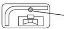
natural_image
Pure technical line drawing of a mechanical component without any text, numbers, or symbols(1
(2
(3
text_image
A B H H/2| D C B A | |||||
| 500 | 300 | 1000 | 300 | ||
(H)
text_image
C D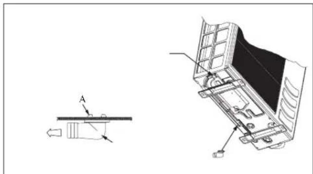
natural_image
Technical line drawing of a mechanical assembly with a cross-sectional view and a small mechanical component labeled A (no text or symbols present)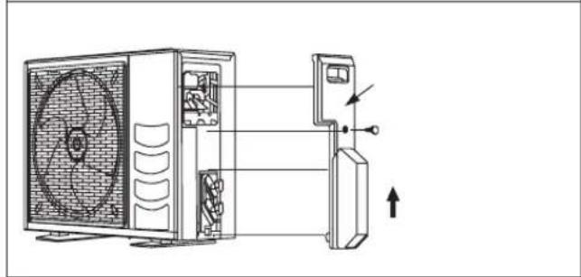
natural_image
Diagram of a front-end air conditioner unit with internal fan and cooling unit, showing airflow direction (no text or labels)•
•
•
text_image
50 M4 x 12L 500
natural_image
A plain gray rectangular shape with no text, symbols, or discernible features.
text_image
Technical diagram showing three mechanical or structural assembly configurations with directional arrows and component placement.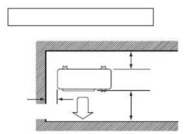
text_image
Technical diagram showing a mechanical assembly with labeled components and directional arrows indicating movement or force.text_image
Contains fluorinated greenhouse gases R410A ①= kg ②= kg ①+②= kg 6 5 4 1 2 32
(2)
*
text_image
Two identical document panels with warning symbols and bullet points, one showing a triangle symbol and the other displaying an exclamation mark.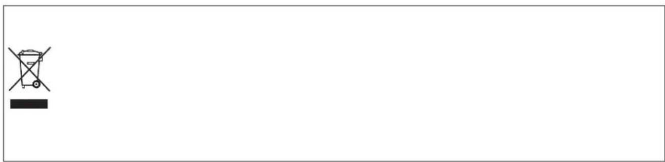
natural_image
Simple line drawing of a trash bin with cross symbol and black rectangle at bottom (no text or labels)[ARXN]
| ABCDEFGHIJKLMNOPQ | ||||||||||||||||
| 299 | 10 | 8 | 133 | 14 | 60 | 94 | 93 | 96 | 470 | 14 | 16 | 273 | 11 | 51 | 658 | 550 |
| O | N | M | L | K | J | I | H | G | F | E | D | C | B | A | |
| 34 | 15 | 164 | 126 | 603 | 113 | 101 | 149 | 93 | 46 | 179 | 520 | 328 | 628 | 855 | 50 NV |
| 34 | 15 | 164 | 126 | 603 | 113 | 101 | 149 | 93 | 46 | 179 | 520 | 328 | 730 | 855 | 60 NV, 50/60 MV |
| V | UQRSTP | ||||||
| 7 | 67 | 8 | 75 | 73 | 362 | 23 | 50 NV |
| 7 | 67 | 8 | 75 | 73 | 362 | 23 | 60 NV, 50/60 MV |
text_image
D E F B G H J L M A K I G| ABCDEFGHIJKLM | |||||||||||||
| 52 | 207 | 181 | 153 | 56 | 55 | 46 | 30 | 141 | 104 | 212 | 288 | 800 | 25/35 MV |
| 52 | 207 | 181 | 153 | 56 | 55 | 46 | 30 | 141 | 104 | 209 | 288 | 859 | 25/35 NV |
text_image
D E F B G H J L M A K I| ABCDEFGHIJKLM | |||||||||||||
| 45 | 580 | 219 | 91 | 48 | 45 | 40 | 61 | 173 | 190 | 228 | 310 | 1065 | 50/60 MV |
| 45 | 580 | 219 | 91 | 48 | 45 | 40 | 61 | 173 | 190 | 237 | 310 | 1124 | 50/60 NV |
text_image
D E F B G H J L M A K I G 65| ABCDHBHGHIJ | ||||||||||||
| 52 | 263 | 182 | 154 | 56 | 55 | 46 | 42 | 184 | 166 | 212 | 288 | 800 |
| 52 | 263 | 182 | 154 | 56 | 55 | 46 | 42 | 184 | 166 | 209 | 288 | 859 |
R410A
INVERTER
ATXN25MV1B7ARXI
ATXN35MV1B7ARXI
ATXN50MV1B7ARXN
ATXN60MV1B7ARXI
ATXN25NV1BARX
ATXN35NV1BARX
ATXN50NV1BARX
ATXN60NV1BARX