
BVH80 - Cooker BAUKNECHT - Free user manual and instructions
Find the device manual for free BVH80 BAUKNECHT in PDF.
| Product type | Cooker with induction hob and integrated hood |
| Brand | Bauknecht |
| Model | BVH80 |
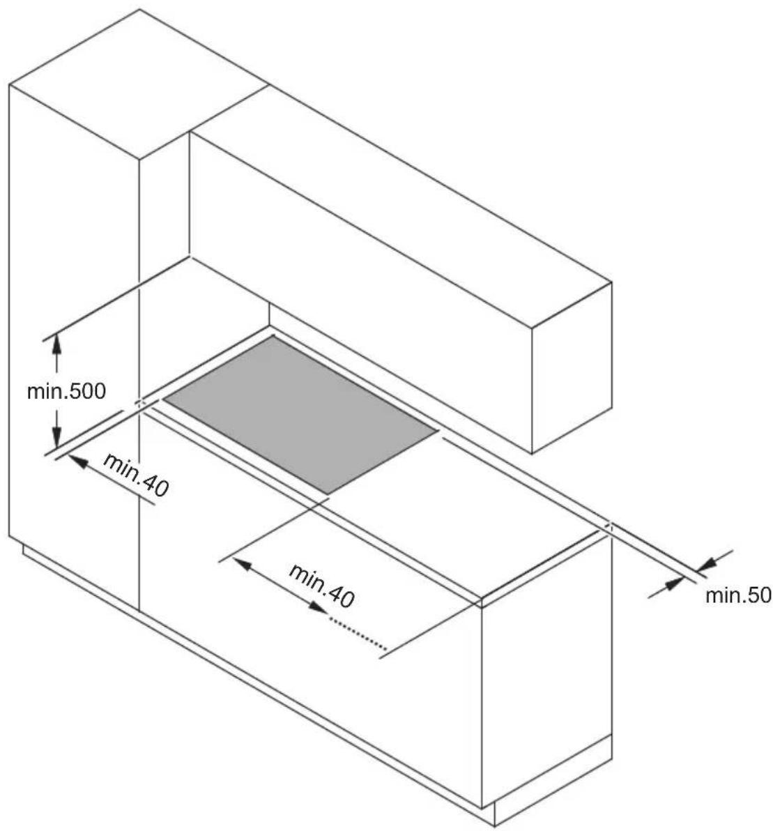
| Dimensions (H x W x D) | 22.3 x 83 x 51.5 cm |
| Number of cooking zones | 4 induction zones |
| Power levels | 9 levels + Power Booster |
| Cooking functions | Automatic Heat Up, Temperature Manager, Bridge Zones, Pause, Timer zones and stand-alone, Power Limitation |
| Extraction type | Suction (external evacuation) or recirculation (internal recycling) |
| Extraction speeds | 3 speeds + 2 Power Booster (15 and 5 min) |
| Automatic hood operation | Yes, automatic adaptation to cooking power |
| Grease filters | Metal, dishwasher safe |
| Odor filters | Activated carbon/ceramic, regenerable in oven (200°C, 45 min) |
| Filter saturation indicator | Yes, can be activated/deactivated, with reset |
| Key Lock | Yes |
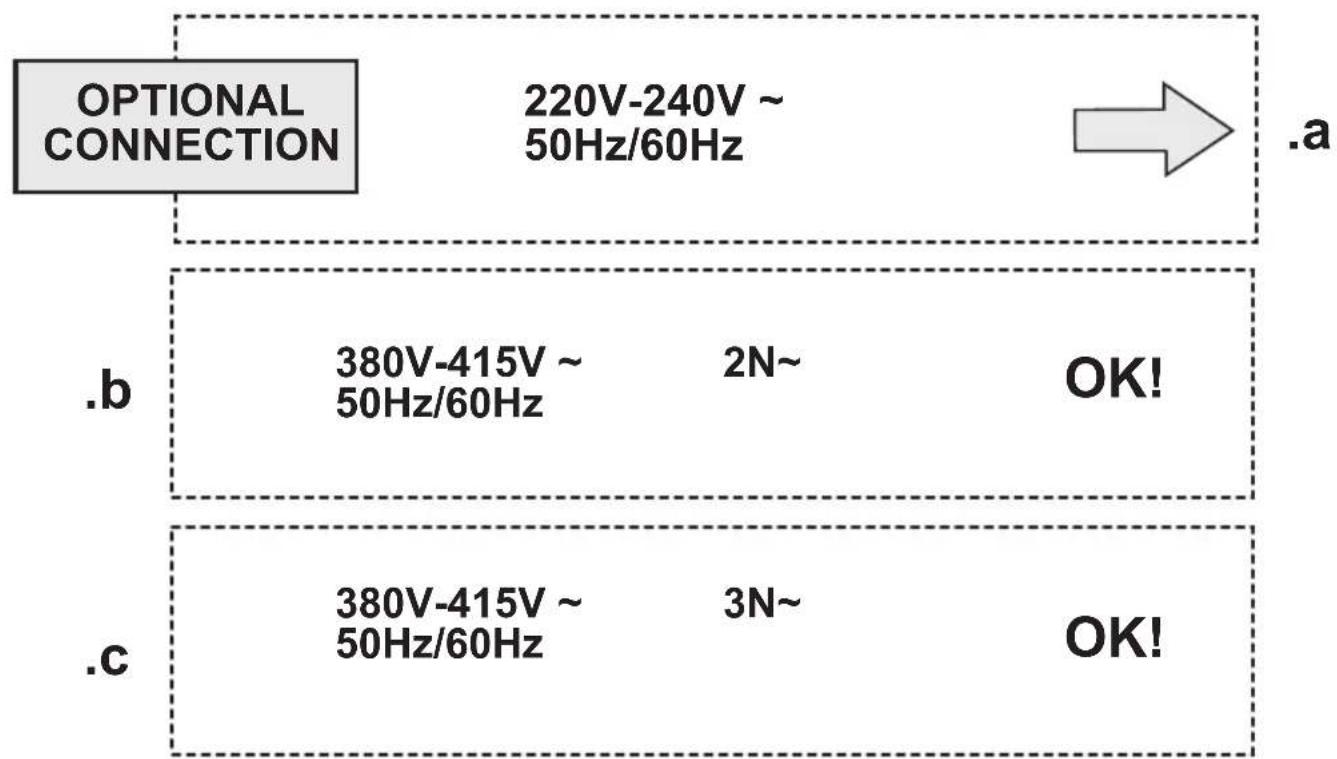
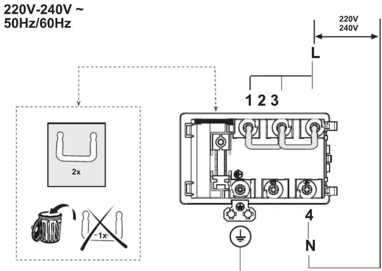
| Electrical supply | Single phase 220-240 V, 50/60 Hz; maximum power 7.4 kW (adjustable via Power Limitation) |
| Power cable | H05V2V2-F 3G4 (single phase); replacement by authorized technician |
| Installation | Built-in TOP or FLUSH, worktop thickness 2-6 cm; minimum distance to walls: 5 cm front, 4 cm sides, 50 cm above |
| Cleaning the hob | Soft cloth, specific products; avoid abrasive sponges and steam cleaners |
| Liquid recovery tray | Yes, drainable and removable |
| Safety | Pan detection, safety shut-off, overheating, residual heat indicator, child lock (Key Lock) |
| Weight | Not specified in the manual |
| Spare parts and repairability | Power cable and filters available through authorized service |
Frequently Asked Questions - BVH80 BAUKNECHT
User questions about BVH80 BAUKNECHT
0 question about this device. Answer the ones you know or ask your own.
Ask a new question about this device
Download the instructions for your Cooker in PDF format for free! Find your manual BVH80 - BAUKNECHT and take your electronic device back in hand. On this page are published all the documents necessary for the use of your device. BVH80 by BAUKNECHT.
USER MANUAL BVH80 BAUKNECHT
natural_image
Technical line drawing of a mechanical component with mounting bracket and side panel (no text or symbols)
natural_image
Two identical black silhouette figures of men, no text or symbols present
natural_image
Illustration of two hands, one white and one gray, overlapping without any text or symbols
natural_image
Technical line drawing of a mechanical assembly with directional arrows indicating motion (no text or symbols)
natural_image
Diagram of a ventilation system with airflow arrows indicating down or up motion (no text or symbols)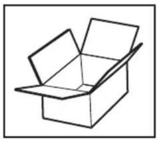
natural_image
Simple line drawing of an open cardboard box (no text or symbols)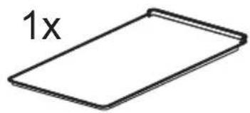
2x ♦∅3,5x9,5mm
natural_image
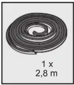
Simple line drawing of a rolled-up tire or tape (no text or symbols)1x 2,8 m
natural_image
Simple line drawing of a rectangular box with a 1x label on the top side (no other text or symbols)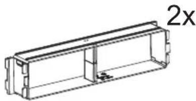
natural_image
Technical line drawing of a rectangular mechanical housing or enclosure with internal components, labeled '2x' (no text or symbols on the diagram itself)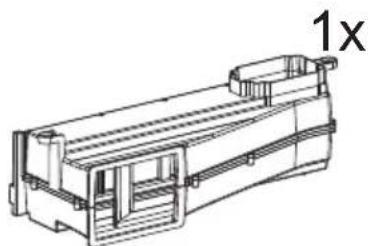
natural_image
Technical line drawing of a mechanical component with no visible text or symbols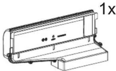
natural_image
Technical line drawing of a mechanical component with no visible text or symbols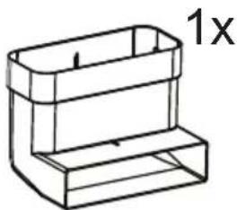
natural_image
Simple line drawing of a rectangular container with a 1x label (no text or symbols on the container itself)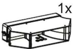
natural_image
Line drawing of a rectangular mechanical component with internal supports and a labeled dimension '1x' (no text or symbols beyond the label)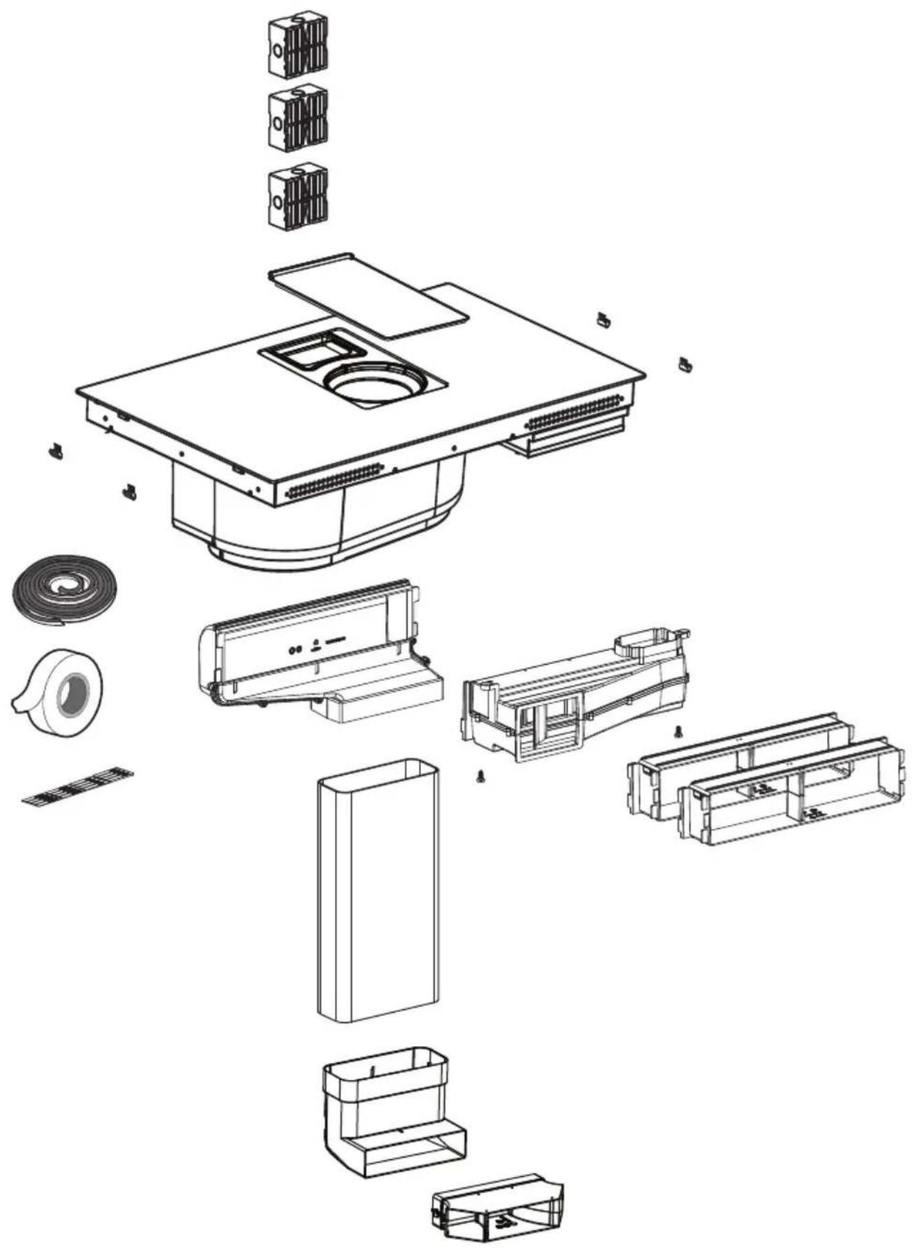
natural_image
Exploded view diagram of a device's internal components, including housing, casing, and accessories (no text or labels)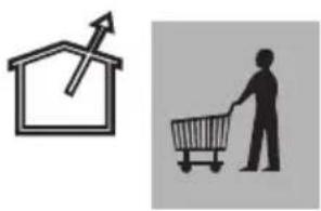
natural_image
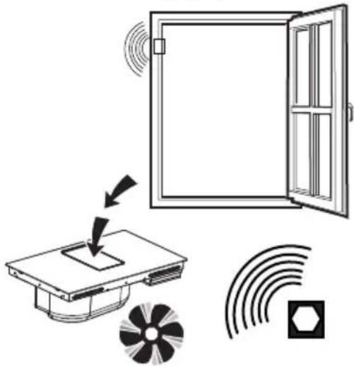
Two simple icons: a house with an upward arrow and a shopping cart, next to a person (no text or symbols)KIT WINDOW
OFF
natural_image
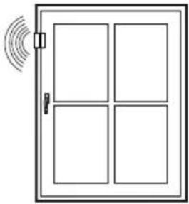
Simple line drawing of a door with four windows and a sensor icon emitting sound waves (no text or symbols)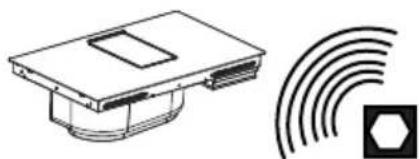
natural_image
Technical line drawing of a device with a hexagonal symbol and concentric arcs (no text or labels)ON
natural_image
Diagram showing a door opening with sound waves, a device with a fan, and signal icons (no text or labels)KIT WINDOW
natural_image
Technical line drawing of a mechanical device with internal components and mounting brackets (no text or symbols)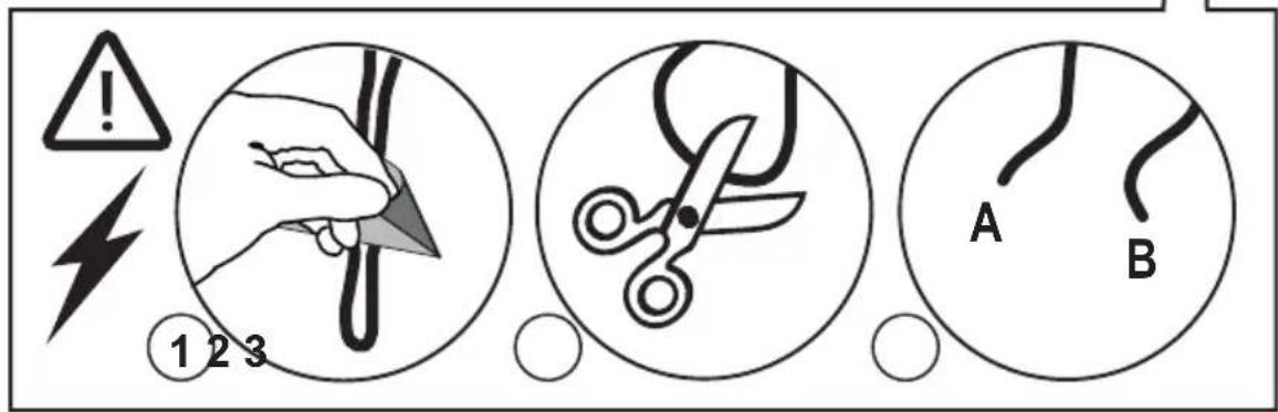
natural_image
Isometric line drawing of a rectangular box with a recessed top frame (no text or symbols)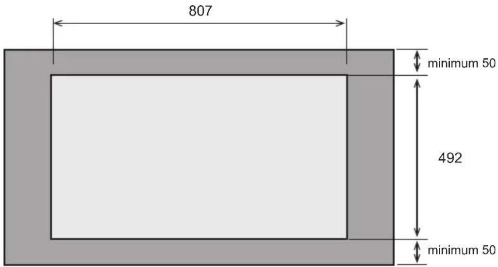
natural_image
Illustration showing a shopping cart and a syringe with a magnified view of the same object (no text or symbols)
natural_image
Circular object with a curved top and base, labeled with dimensions 1 x and 2.8 m (no other text or symbols)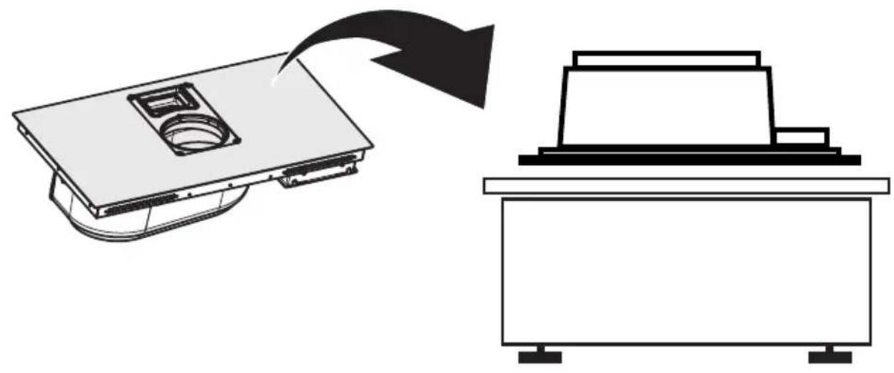
natural_image
Diagram showing a device with a top panel and a separate view of a rectangular device (no text or symbols)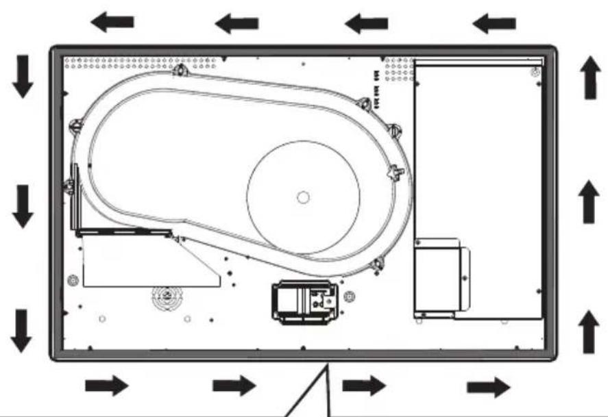
flowchart
graph TD
    A["Top Left Panel"] --> B["Top Right Panel"]
    B --> C["Bottom Left Panel"]
    C --> D["Bottom Right Panel"]
    D --> E["Control Unit"]
    style A fill:#f9f,stroke:#333
    style B fill:#bbf,stroke:#333
    style C fill:#dfd,stroke:#333
    style D fill:#dfd,stroke:#333
    style E fill:#dfd,stroke:#333
natural_image
Circular object with concentric rings, labeled with dimensions 1 x and 2.8 m (no other text or symbols)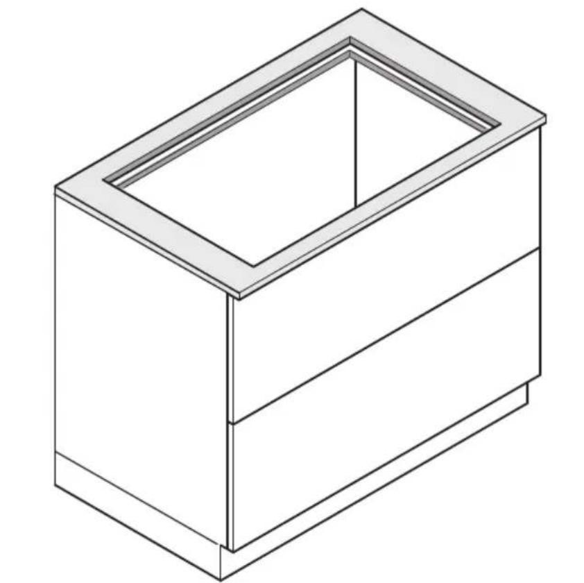
natural_image
Isometric line drawing of a rectangular box with a recessed top frame (no text or symbols)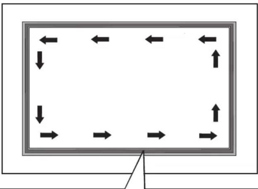
natural_image
Diagram showing bidirectional arrows around a rectangular frame, no text or symbols present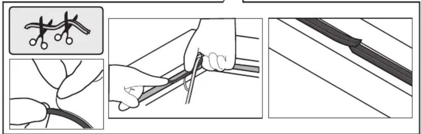
other
OPTIONAL CONNECTION 220V-240V ~ 50Hz/60Hz .a .b 380V-415V ~ 2N~ 50Hz/60Hz OK! .c 380V-415V ~ 3N~ 50Hz/60Hz OK!3
.a
.b
.C
4
natural_image
Isometric line drawing of a rectangular box with internal compartments and arrows indicating movement or force (no text or symbols)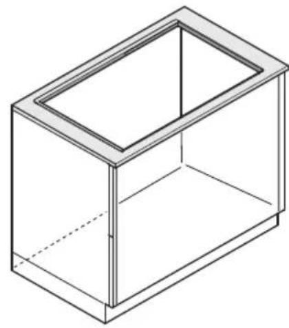
natural_image
Isometric line drawing of a rectangular box with a recessed top (no text or symbols)OK!
natural_image
Simple line drawing of a mechanical component with no text or symbols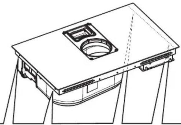
natural_image
Technical line drawing of a mechanical component with mounting brackets and a central circular opening (no text or symbols)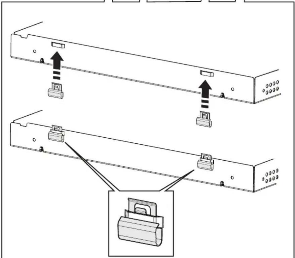
natural_image
Isometric line drawing of a rectangular box with a black square on top and dimension label '600' (no text or symbols beyond the label)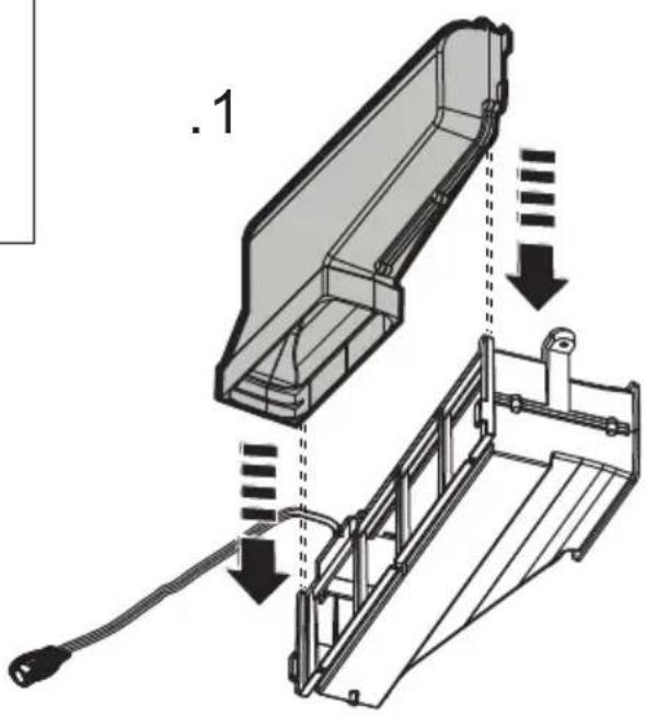

natural_image
Isometric diagram of a rectangular box with a black square on top and dimension label '650' (no text or symbols beyond the label)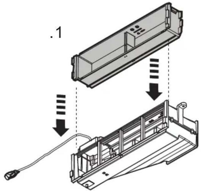
natural_image
Technical line drawing of a mechanical component with no visible text or symbols

natural_image
Isometric diagram of a rectangular box with a central square and dimension label '700' (no text or symbols on the box itself)
natural_image
Technical line drawing of a mechanical component with no visible text or symbols
8

natural_image
Technical diagram showing a mechanical assembly with an arrow indicating direction, no text or symbols present9

10
natural_image
Technical line drawing of a mechanical assembly with three labeled components (no text or symbols present)
natural_image
Two simple icons: a house with an upward arrow and a shopping cart with a person (no text or symbols)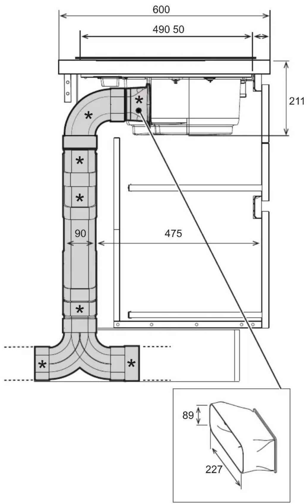
natural_image
Diagram of a 3D rectangular device with internal compartments and mounting holes, labeled X3 (no text or symbols on the device itself)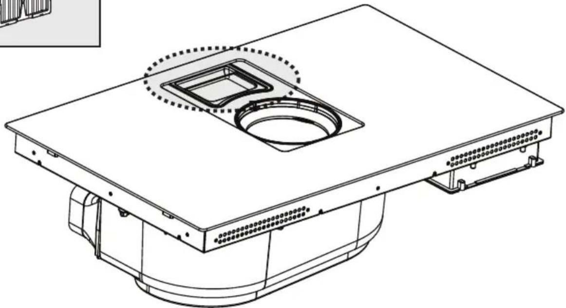
natural_image
Technical line drawing of a mechanical component with a square recess and mounting base (no text or symbols)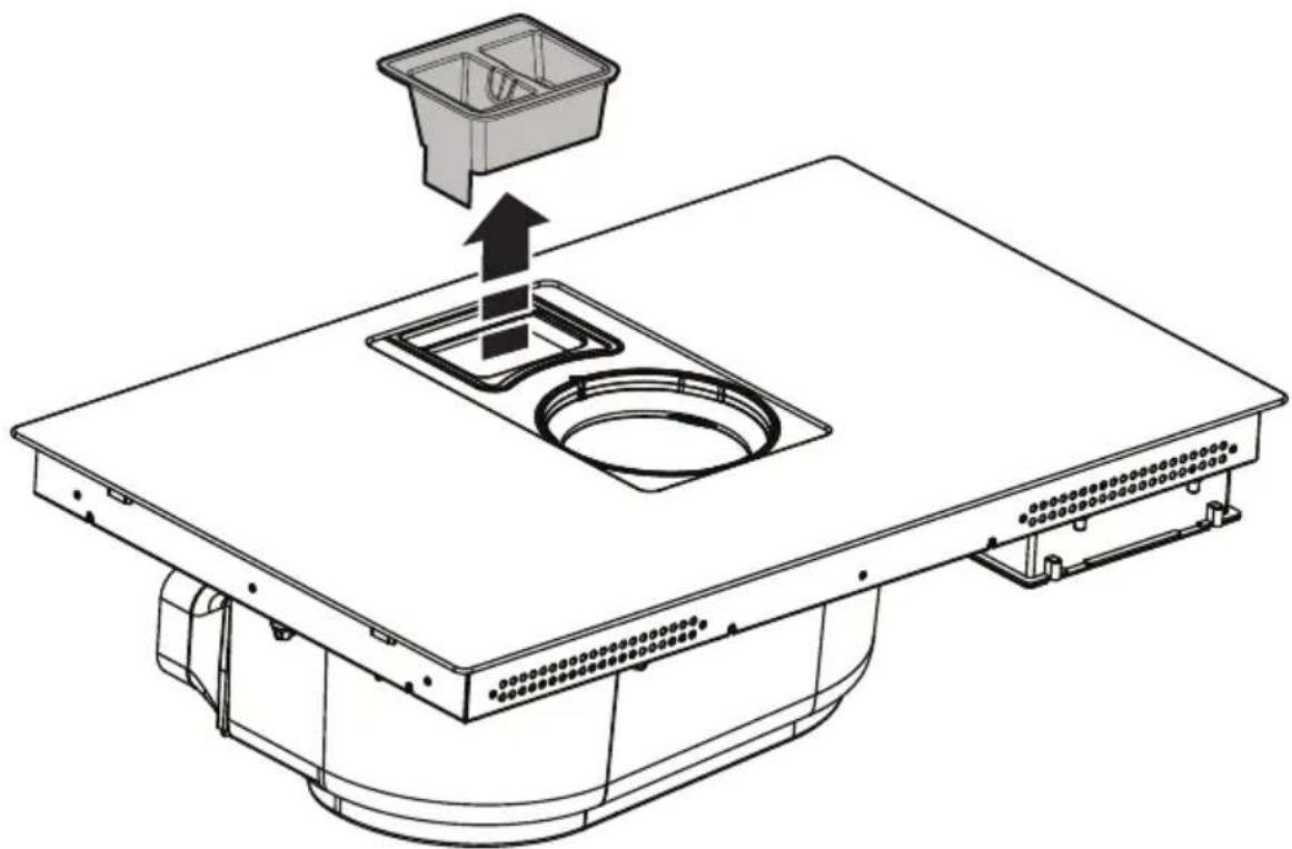
natural_image
Technical line drawing of a mechanical assembly with a central sink and top component, showing internal components and an upward arrow (no text or symbols)
.1
.2
.3

natural_image
Black and white icon of a crossed wrench and screwdriver (no text or symbols)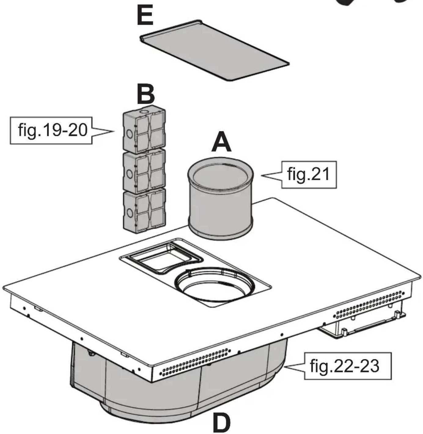

B
.1
natural_image
Diagram of a printer or printer device with a screen and base, showing a paper roll and directional arrow (no text or symbols).2
natural_image
Technical line drawing of a mechanical assembly with a central component and upward arrow indicator (no text or symbols).3
natural_image
Diagram of a mechanical or electrical assembly with a device and wiring, labeled 'B' (no text or symbols on the diagram itself)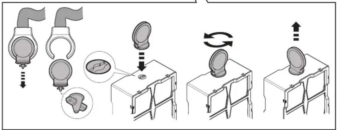
flowchart
graph TD
    A["Initial catheter insertion"] --> B["Initial catheter placement"]
    B --> C{Check position}
    C --> D["Device placement"]
    D --> E["Device placement with circular component"]
    E --> F["Device placement with circular component and loop"]
    F --> G["Device placement with circular component and loop back to plate"]
    G --> H["Device placement with circular component and loop back to plate"]

B
natural_image
Diagram of a mechanical setup with a device and mounting base, no visible text or symbols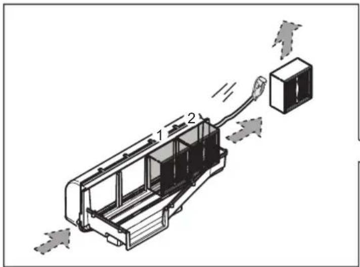
natural_image
Diagram of a mechanical setup with a device and mounting base, no visible text or symbols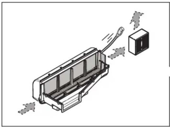
natural_image
Diagram of a device with a cable and connector, showing airflow direction (no text or symbols)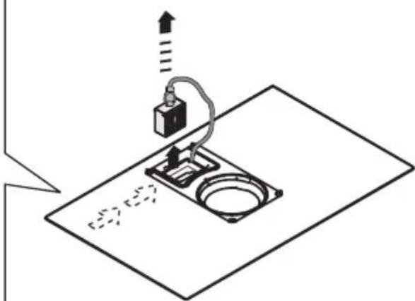
natural_image
Diagram of a mechanical setup with a device and base, no visible text or symbols
natural_image
Diagram of a printer or printer device with a paper lid and fan blade, showing no text or symbols.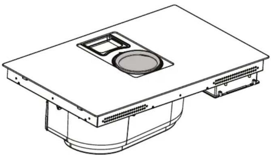
natural_image
Technical line drawing of a mechanical or electrical component with a central circular opening and mounting base (no text or symbols)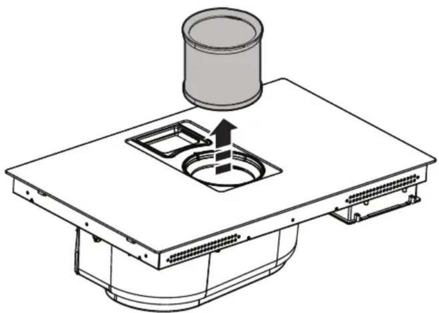
natural_image
Technical line drawing of a mechanical component with a cylindrical component and a square opening (no text or symbols)
natural_image
Technical line drawing of a mechanical device interior with no visible text or symbols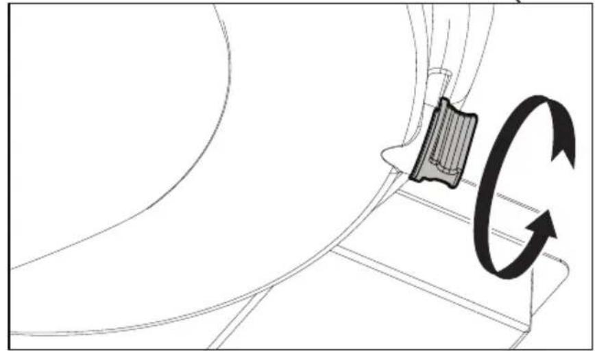
natural_image
Diagram showing a mechanical component with a rotating arrow indicating rotational motion (no text or symbols present)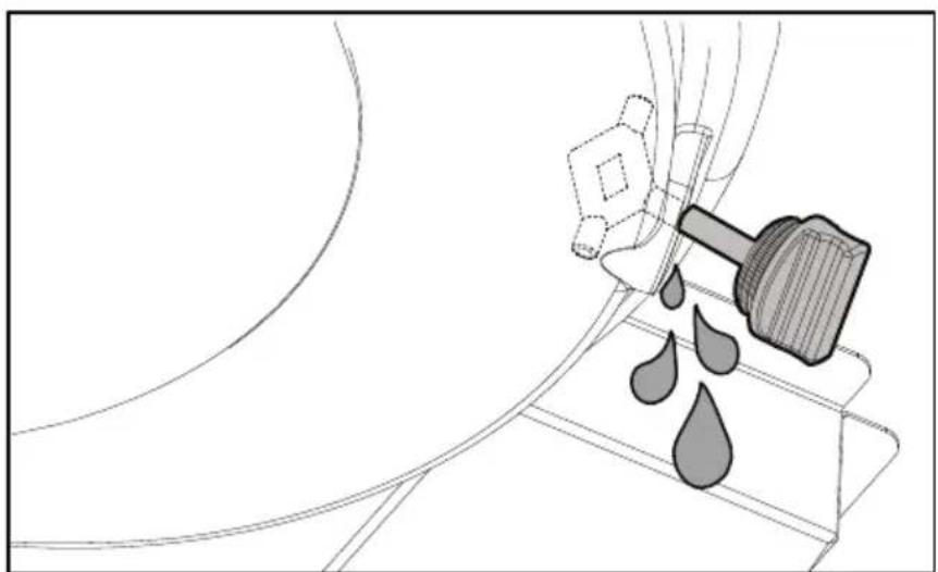
natural_image
Diagram of a mechanical device with a hammer and droplet, no text or symbols present
natural_image
Technical diagram of a mechanical device with internal components and directional arrows, showing a close-up of the component (no text or symbols present)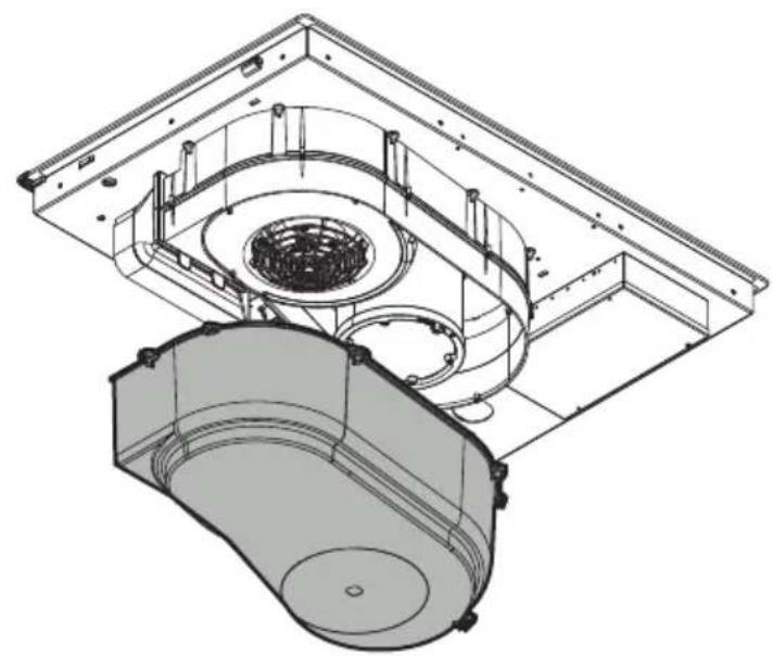
natural_image
Technical line drawing of a mechanical assembly with internal components (no text or symbols)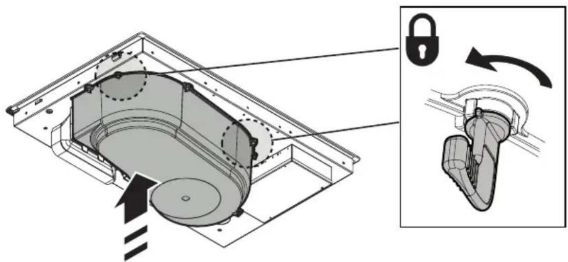
natural_image
Technical illustration of a mechanical device with internal components and a close-up view showing a lock mechanism (no text or symbols present)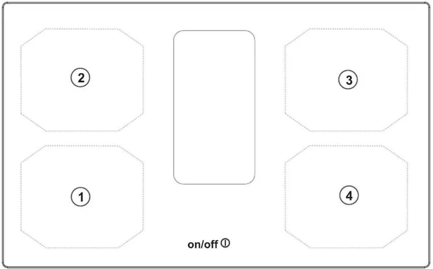

IT
SICUREZZA GENERALE
T. Funzione
• Residual Heat Indicator
• Temperature Manager (Warming Function)
natural_image
Silhouette of a person pushing a shopping cart (no text or symbols)EN
GENERAL SAFETY
Please note! Pay strict attention to the following instructions: ● The device must be disconnected from the mains before carrying out any installation work. ● Installation or maintenance must be performed by a qualified technician, in compliance with the manufacturer's instructions and local safety regulations. Do not repair or replace any part of the product unless specifically stated in the operating manual. ● By law, the product must be earthed. ● The power cable must be long enough to allow the product, built into the cabinet, to be connected to the mains. ● In order for the installation to comply with current safety regulations, an approved omnipolar switch is required that guarantees complete disconnection from the mains in overvoltage category III, in accordance with the installation rules. ● Do not use power strips or extension cords. ● Once installation is complete, the electrical components must no longer be accessible by the user. ● The product and its accessible parts get hot during use. Be careful not to touch the heating elements. ● Ensure that children do not play with the product; keep children at a safe distance and supervise them as the accessible parts may become very hot during use. ● For people with pacemakers and active implants, it is important to check, prior to using the induction hob, that their pacemaker is compatible with the product. ● Do not touch the heating elements of the product during and after use. ● Avoid contact with kitchen towels or other flammable materials until all components of the product have sufficiently cooled, fire hazard. ● Do not place flammable materials on or near the product. ● Overheated fats and oils easily catch fire. Supervise the cooking of fatty or oily food. ● If the surface is cracked, switch the product off immediately to prevent the risk of an electric shock. ● The product is not intended to be operated with an external timer or a separate remote control system. ● Unattended cooking on a hob with oil or fat can be dangerous and may cause a fire. ● The cooking process must be supervised. A short cooking process must be constantly monitored. ● NEVER attempt to put fires out using water. Instead, turn off the product and smother the flames, for example with a lid or a fire blanket. ● Fire hazard: do not place objects on the cooking surfaces. ● Do not use steam cleaners, risk of electric shock. ● Do not place metal objects, such as knives, forks, spoons or lids on the hob because they could become hot. ● Before connecting the product to the mains: check the rating plate (on the bottom of the product) to ensure that the voltage and power correspond to the mains supply and that the power socket is suitable. If in doubt, consult a qualified electrician.
Important: ● After use, turn off the hob using its control device and do not rely on the pot detector. ● Prevent liquids from boiling over; therefore, turn the heat down when boiling or heating liquids. ● Do not leave the heating elements turned on with empty pots and pans, or without any cookware. ● Switch off the relevant cooking zone when you have finished cooking. ● Never use aluminium foil for cooking and never place products packaged in aluminium directly on the hob. The
aluminium would melt and irreparably damage your product. ● Never heat a tin or can containing foods without opening it first: it might explode! This warning also applies to all other types of hobs. ● High power levels such as the Booster function should not be used to heat certain liquids, such as oil for frying. Excessive heat may be dangerous. In these cases, we recommend the use of a lower power level. ● The cookware must be placed directly on the hob and must be centred. Under no circumstances may any other objects be placed between the pot and the hob. ● If the temperature becomes high, the product automatically decreases the power level of the cooking zones. ● Before doing any cleaning or maintenance work, disconnect the product from the mains by disconnecting the plug or turning off the mains switch. ● For all installation and maintenance operations, always use work gloves. ● The product can be used by children over the age of 8 and by people with reduced physical, sensory or mental capabilities or without experience or the necessary knowledge, as long as they are properly supervised or have been instructed on how to safely use the product and understand the inherent dangers. ● Children must be supervised to ensure they do not play with the product. ● Cleaning and maintenance must never be performed by children unless they are properly supervised. ● The room must be sufficiently ventilated when the product is used at the same time as other appliances that run on gas or other fuels. ● The product must be cleaned frequently both inside and out (AT LEAST ONCE A MONTH); always follow the instructions given in the maintenance manual. ● Failure to comply with the rules for product cleaning and the cleaning/replacement of filters, may create a fire hazard. ● Flambé cooking is strictly prohibited. ● Using a naked flame may damage the filters and cause a fire hazard, and must therefore be avoided under all circumstances. ● Extra care must be taken when frying to prevent the oil from overheating and catching fire. ● Please note! The accessible parts of the device may become hot when the hob is switched on. ● Please note! Do not connect the product to the mains until the installation is complete. ● The regulations laid down by local authorities must be strictly followed with regard to the technical and safety measures to be adopted for fume extraction. ● The extracted air must not be conveyed through the same ducts used to extract the fumes generated by the combustion of gas or other types of fuels. ● Never use the product without the grille properly installed! ● Only use the fastening screws supplied with the product for installation, or if not supplied, purchase the correct type of screws. Use screws of the right length, as indicated in the installation guide. ● When this product is used together with other devices powered with non-electrical energy, the negative pressure of the room must not exceed 4 Pa (4 x 10⁻⁵ bar). ● This manual must be stored for future consultation at any time. If sold, transferred or moved, it must remain with the product.
- Range hoods and other cooking fume extractors may adversely affect the safe operation of appliances burning gas or other fuels (including those in other rooms) due to back flow of combustion gases. These gases can potentially result in carbon monoxide poisoning. After installation of a range hood or other cooking
fume extractor, the operation of flued gas appliances should be tested by a competent person to ensure that back flow of combustion gases does not occur. ● During installation, check that the power cord is not damaged risk of fire and electric shocks. Do not use the device with bare feet or if you are not dry. Start the device only once installation is complete. ● Do not use the device if the power cord or plug are damaged, in case of abnormal operation, or if the device is damaged or has fallen. ● If the supplied power cord is damaged, it must be replaced with an identical power cord supplied by the producer, authorised technician, or qualified personnel risk of electric shocks. ● The device must be handled and installed by two or more people – risk of injury. ● Keep children away from the installation area. Once installation is complete, the packaging (plastic, polystyrene parts, etc.) must be kept out of reach of children risk of suffocation. ● Children under the age of 3 must be kept away from the device; children between 3 and 8 years of age can approach the device only if strictly supervised. ● This device is not intended for professional use. Do not use the device outdoors.
Strictly observe the instructions in this manual. All liability is declined for any problems, damage or fires caused by failure to comply with the instructions in this manual. The device is intended for domestic use only, to cook food and extract the fumes generated by cooking. No other use is allowed (e.g. heating rooms). The manufacturer declines any liability for inappropriate use or incorrect control settings.
- Read the instructions carefully: they contain important information on installation, operation and safety.
- Do not make electrical changes to the device.
- Before installing the device, make sure that none of the components are damaged. Otherwise, contact the dealer and do not continue with the installation.
- Check that the device is intact before proceeding with installation. Otherwise, contact the dealer and do not continue with the installation.
INSTALLATION
- The electrical and mechanical installation must be performed by qualified personnel.
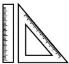
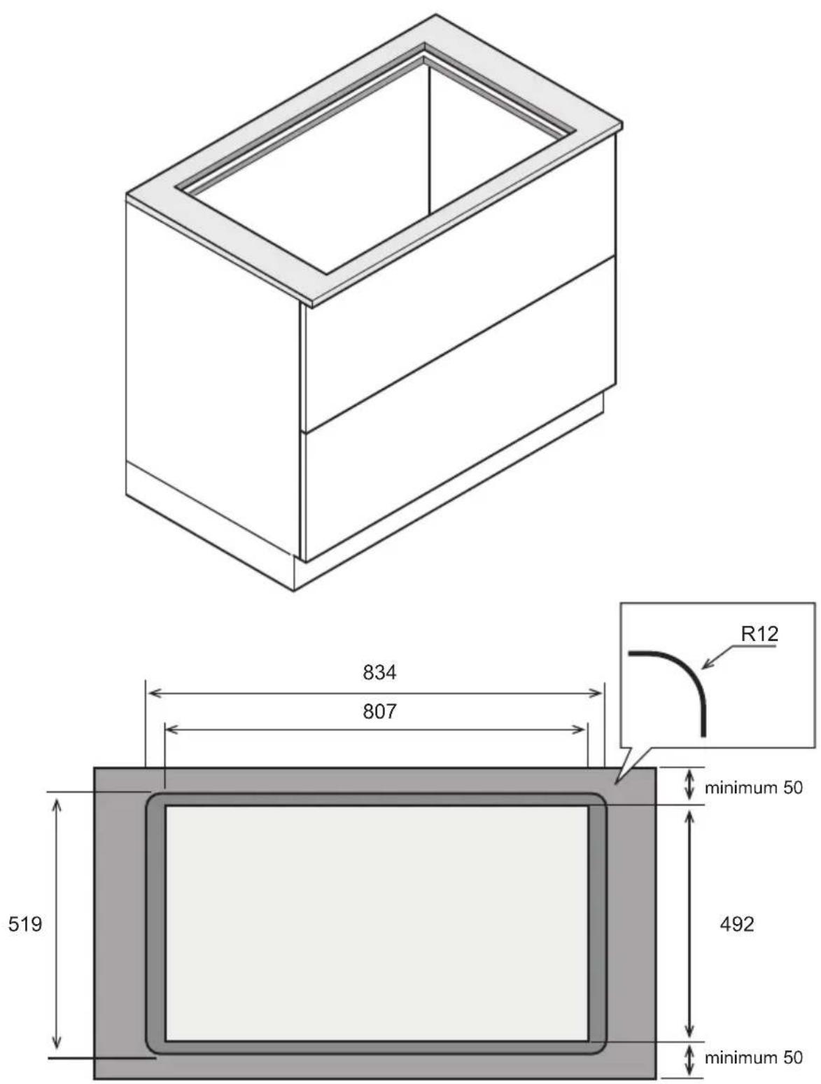
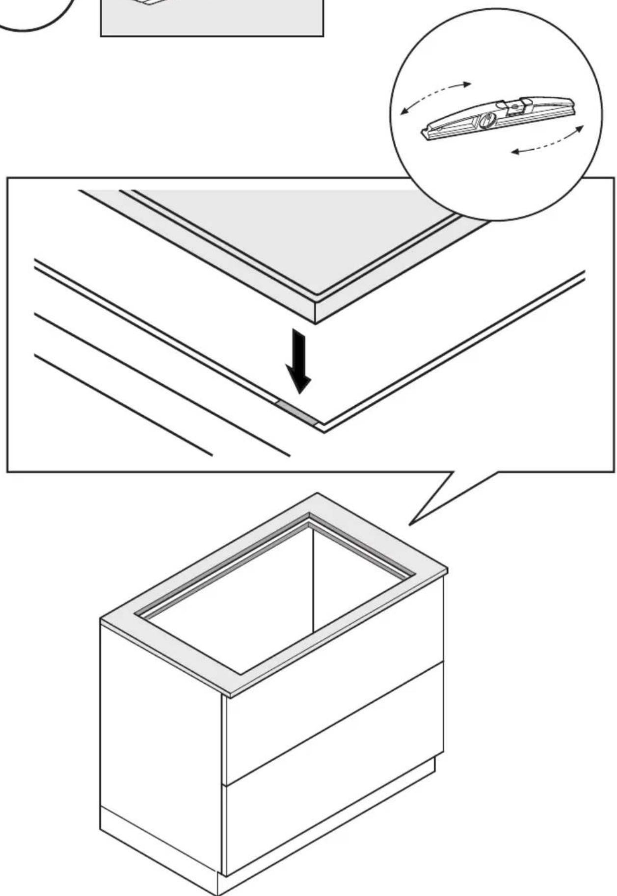
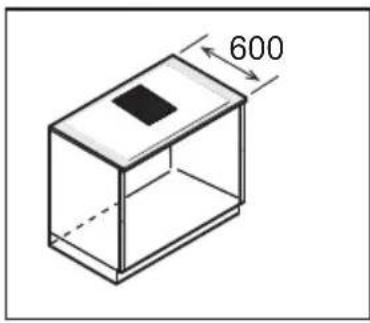
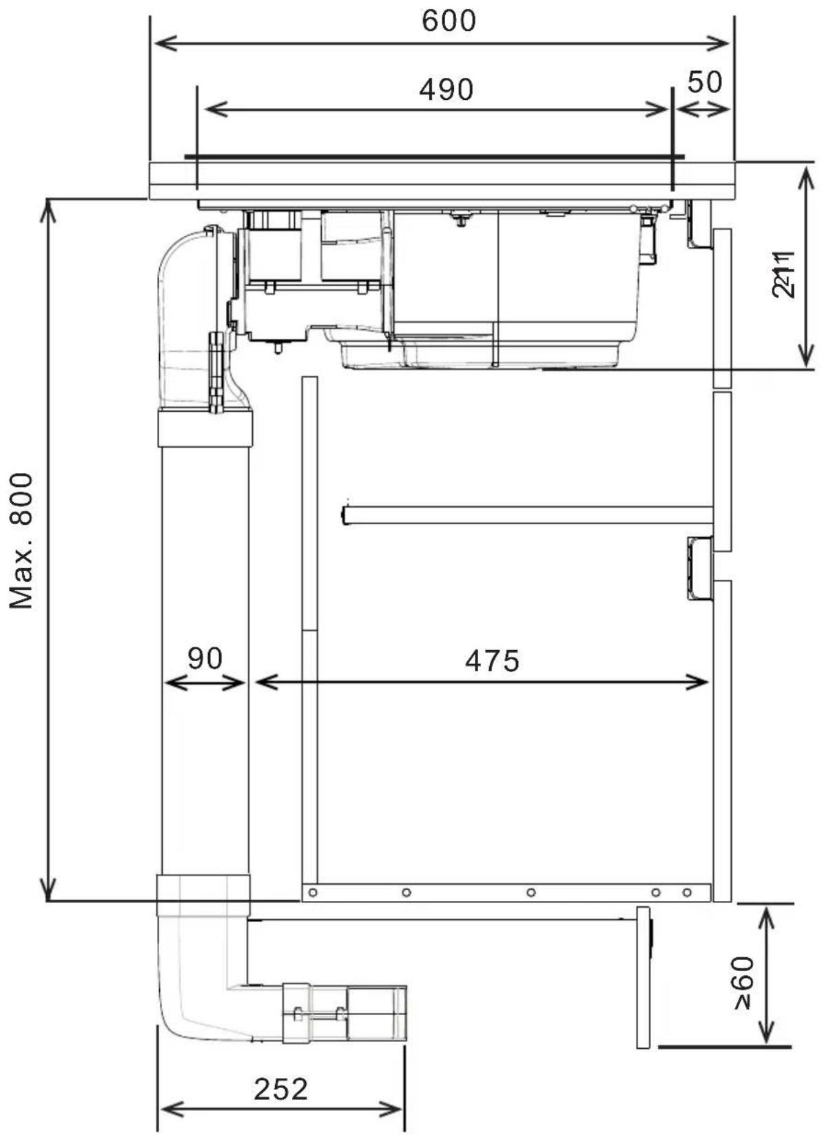
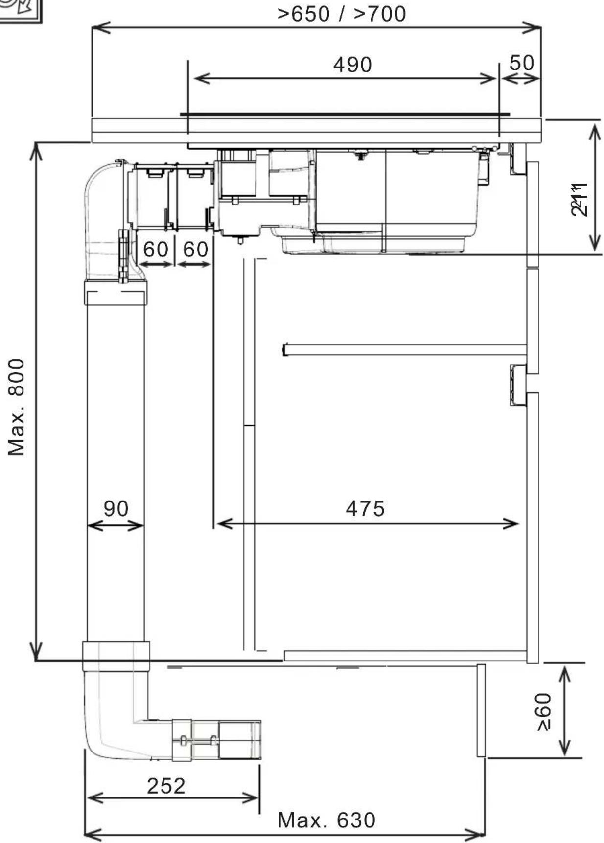
- The product is designed to be built into a worktop with a thickness of 2-6 cm in the case of TOP installation; 2.5-6 cm in the case of FLUSH installation.
The minimum distance between the hob and the wall must be at least 5 cm in front, at least 4 cm on the sides and at least 50 cm from overhead wall units.
NB = The recommended distances are given as examples: when planning the spaces, the indications of the kitchen manufacturer must be observed.
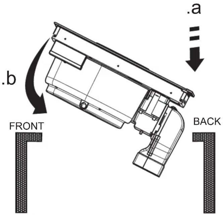
TOP installation: (Fig.1A-2A); FLUSH installation: (Fig.1B-2B)
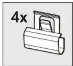
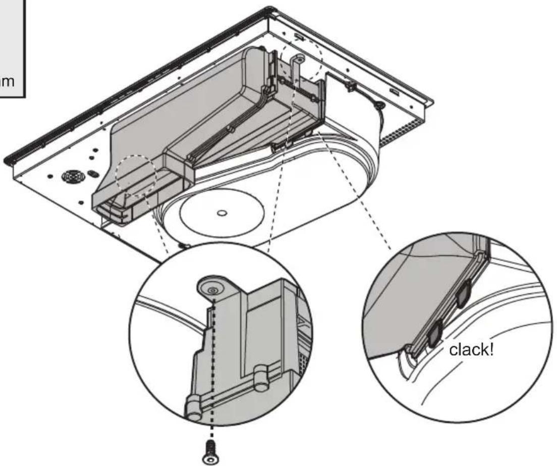
- Please note! Failure to install screws and fasteners in accordance with these instructions may result in electrical hazards.
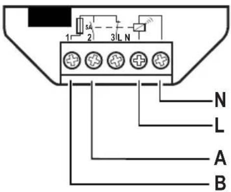
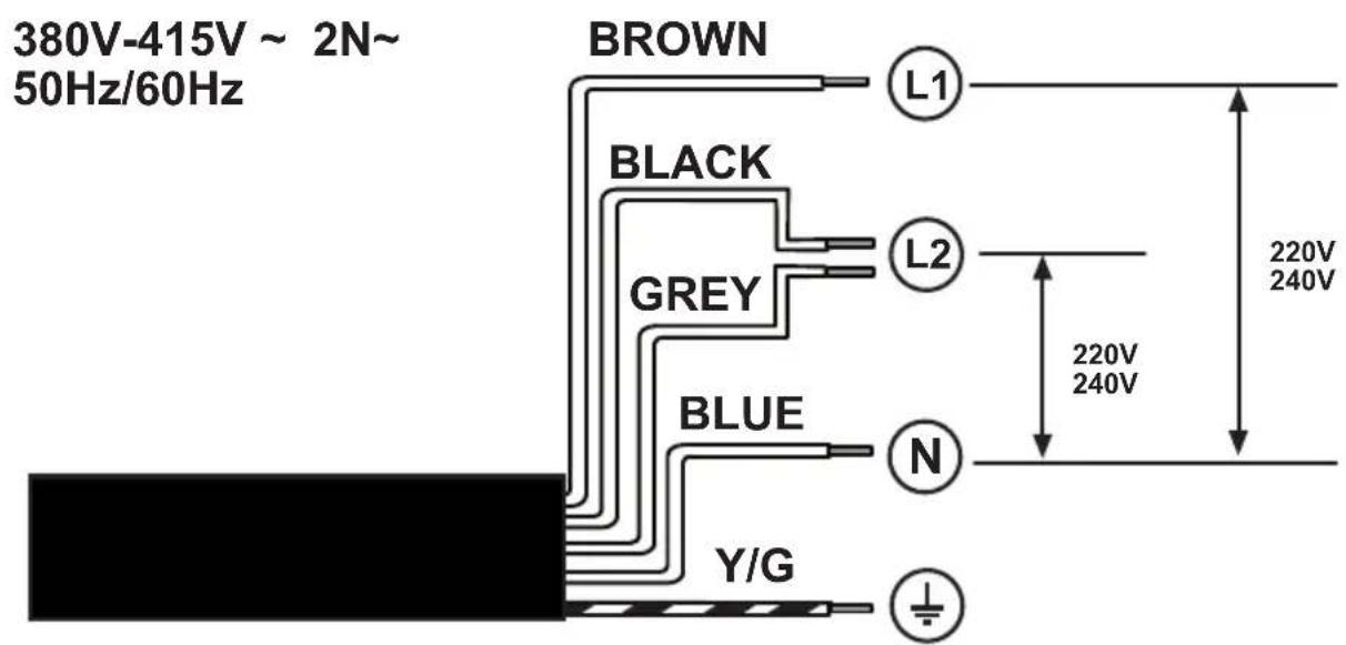
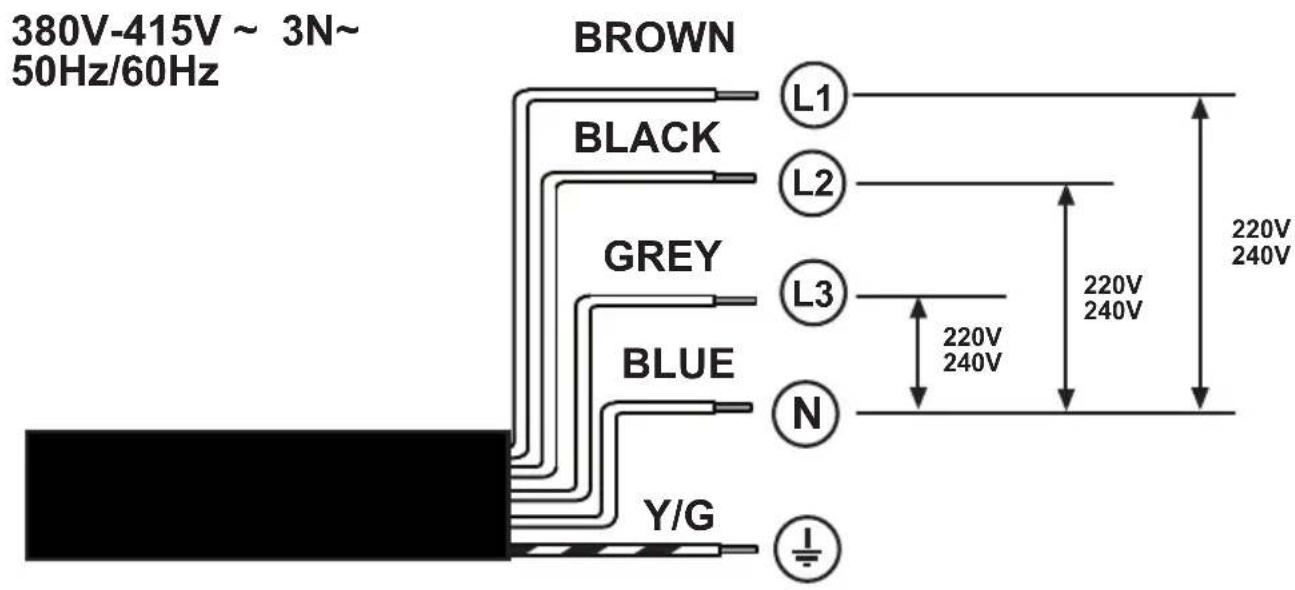
ELECTRICAL CONNECTION
- Disconnect the product from the mains. ● The installation must be carried out
by professionally qualified personnel with knowledge of the regulations in force for installation and safety. ● The manufacturer disclaims all liability for persons, animals or property if the guidelines provided in this chapter are not followed. ● The power cable must be long enough to allow removal of the hob from the worktop. ● Check that the voltage on the rating plate on the bottom of the product corresponds to that of the domestic environment where it will be installed. ● Do not use extension cords. ● The earth cable must be 2cm longer than the other cables. ● If the product is not equipped with a power cable, use one with a minimum conductor diameter of 2.5 mm2 for power up to 7200 Watt; for higher power levels, the diameter must be 4 mm2. ● The temperature must not reach 50°C above room temperature anywhere along the cable. ● The product is intended to be permanently connected to the mains, therefore, make the connection to the mains using an approved omnipolar switch that guarantees complete disconnection from the mains in category III overvoltage conditions, and which is readily accessible after the installation.
- Please note! Before reconnecting the circuit to the mains power supply, make sure that it is working correctly, always check that the power cable is correctly installed.
- Please note! The interconnection cable must be replaced by the authorised customer service representative or by a person with similar qualifications. to connect the electrical appliance with the optional single-phase connection, the existing power cord must be removed and replaced with another type of power cord (not supplied) having the following specifications: single-phase connection :cable H05V2V2-F 3G4.
POWER LIMITATION: the product is equipped with a Power Limitation function, which allows a maximum power limit to be set (kw)
The setting must be made when the product is connected to the mains or when the mains power itself is restored (within the following 2 minutes). Size the electrical system protection according to the selected Power Limitation level. For the Power Limitation setting sequence, see the Operation section of this manual.
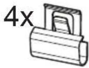
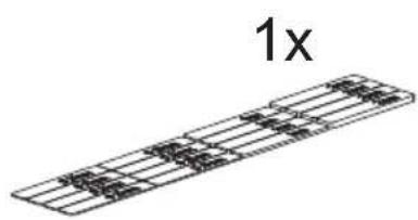
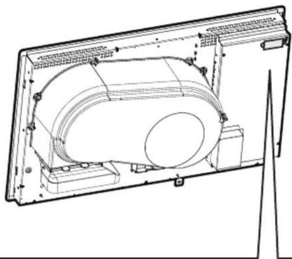
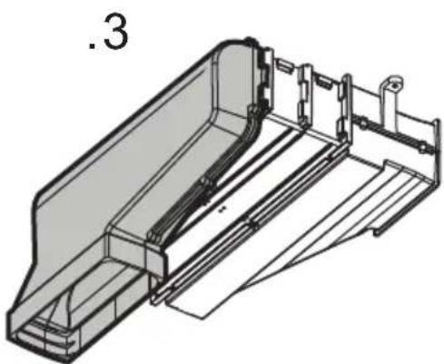
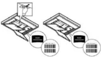
ASSEMBLY
- Before starting the installation: After unpacking the product, check that it has not been damaged during transport and in the case of problems, contact your dealer or Customer Service, before proceeding with the installation; Check that the purchased product is the right size for the installation location; Check for accessories inside the packaging (placed there for ease of transport, such as bags containing screws, the warranty certificate, etc.). Remove and keep them safe; Also check that there is a power socket near the installation area
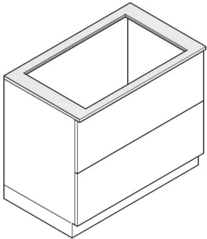
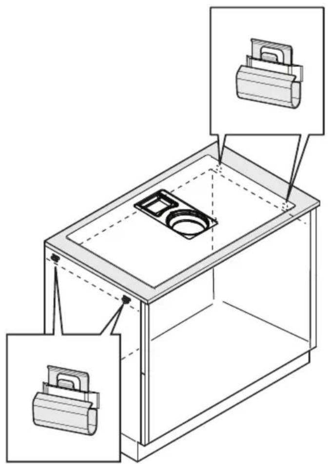
- Preparing the cabinet for installation:
- The product cannot be installed above cooling appliances, dishwashers, heaters, ovens, washing machines and dryers; Create the cut-outs in the cabinet before inserting the hob and carefully remove shavings or sawdust.
- to optimise the recirculating installation, it is recommended to create a slot in the plinth, in which to insert a commercial grille.
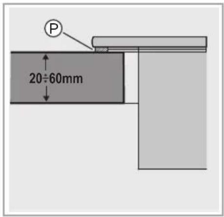
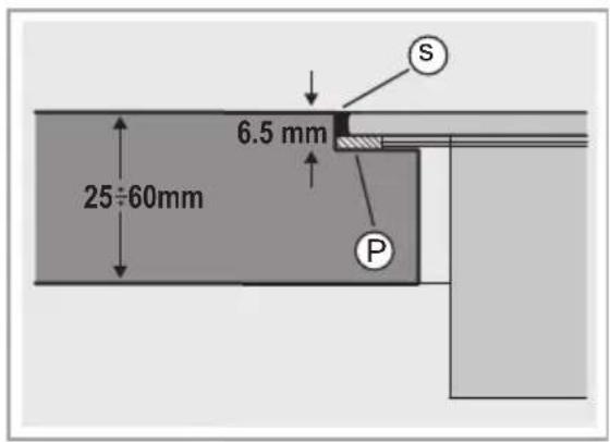
- Important: use a single component adhesive sealant (S) that can withstand high temperatures up to 250^ ; before installation, the surfaces that need to be glued must be thoroughly cleaned, removing all substances that may compromise adhesion (e.g. release agents, preservatives, grease, oils, powders, old adhesive residue, etc.); the adhesive must be evenly spread along the entire perimeter of the frame; after gluing, leave the adhesive to dry for about 24 hours.
The single-component adhesive sealant (S) should only be used in the case of Flush installation, taking care to place it as shown in Fig.1B.
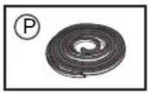
When installing the gasket (P), take care to position it correctly as shown in the figure:
- TOP installation: the gasket (P) must be attached to the glass Fig.2A.
- FLUSH installation - the gasket (P) must be attached to the furniture. Fig.2B.
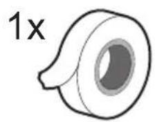
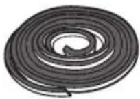
- Note: for correct installation of the product, it is recommended to tape the pipes using an adhesive with the following characteristics: soft elastic PVC film, with acrylic-based adhesive; complies with DIN EN 60454 regulations; flame retardant; excellent resistance against wear; resistant to temperature fluctuations; can be used at low temperatures.
OTHER USEFUL INFORMATION
The device may have different aesthetic features with respect to the illustrations in this handbook, however the operating, maintenance and installation instructions remain the same.
USE
USING THE HOB
The induction cooking system is based on the physical phenomenon of magnetic induction. The main characteristic of this system is the direct transfer of energy from the generator to the pot.
Benefits: When compared to electric hobs, your induction hob is: Safer: lower temperature on the glass surface. Faster: shorter food heating times. More accurate: the hob immediately reacts to your commands. More efficient: 90% of the absorbed energy is transformed into heat. Moreover, once the pot is removed from the hob, heat transmission is immediately interrupted, avoiding unnecessary heat loss.
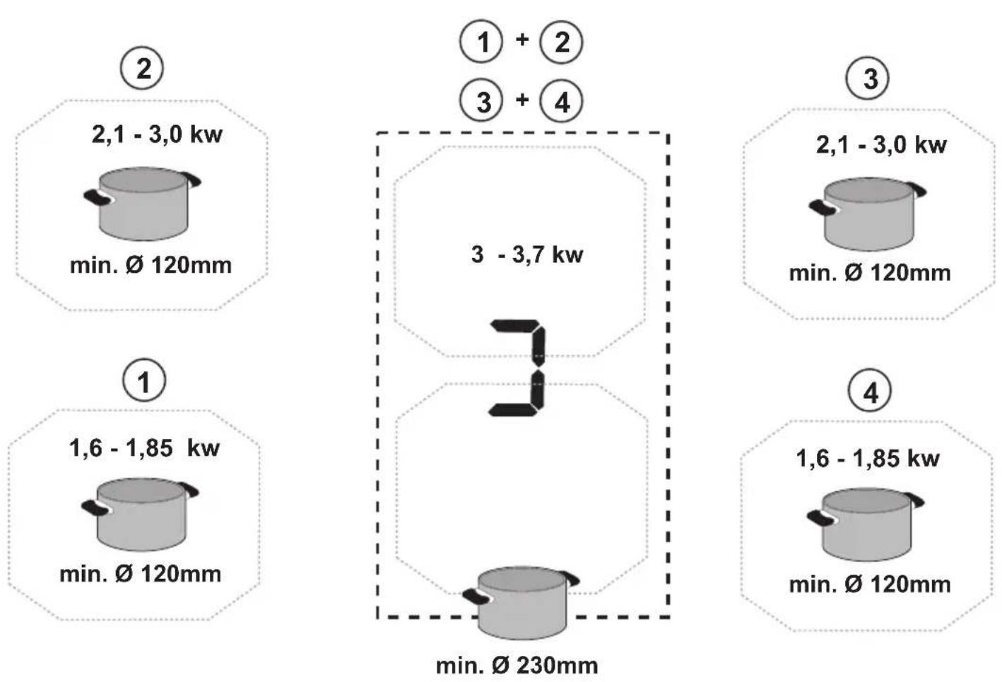
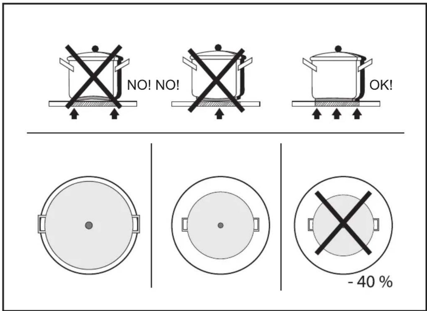
- Recommended pot bottom diameters
IMPORTANT: if the pots are not of the correct size, the cooking zones will not switch on. To see the minimum pot diameters for each individual zone, consult the illustrated section of this manual.
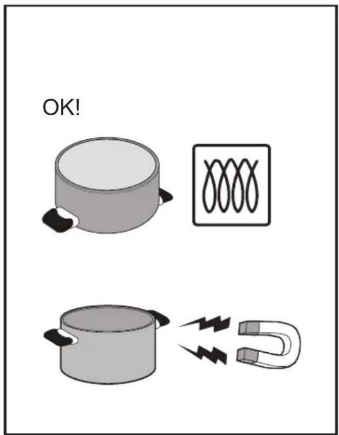
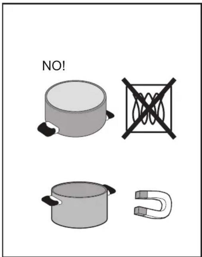
- Cookware
Important:
Use only pots and pans bearing the symbol

to avoid permanent damage to the hob surface, do not use:
• cookware with a base that is not perfectly flat;
• metal cookware with an enamelled base:
• cookware with a rough base, to avoid scratching the hob surface:
- never place hot pots and pans on the surface of the hob's control panel.
●Pre-existing cookware
You can check if the pot material is magnetic simply by using a magnet. Pots are not suitable if they are not magnetically detectable. The indications from the previous paragraph also apply here.
USING THE EXTRACTOR FAN
The extraction system can be used in the duct-out version with external evacuation, or in the recirculating version with filtering and internal recirculation.
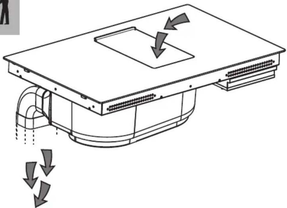
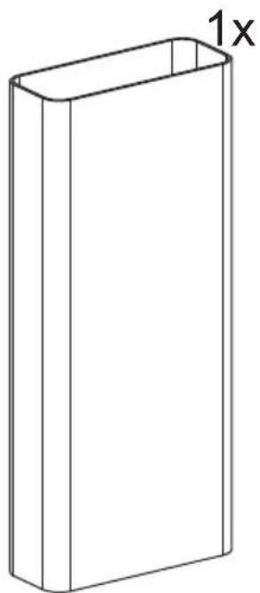
- Duct-Out Version:
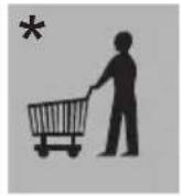
Vapours are exhausted outside via a series of pipes (to be purchased separately). Connect the product to wall-mounted exhaust pipes and holes with a diameter equivalent to the air outlet (connecting flange). For more information on the pipes and their dimensions see the page relating to accessories in the installation manual - Duct-Out version. The use of pipes and outlet holes in the wall with a smaller diameter will reduce the extraction performance and drastically increase the noise level. All responsibility in this regard is therefore denied.
For maximum extraction efficiency: • We recommend a maximum pipe route length of 7 linear metres. • We recommend using no more than two 90° bends along the entire 7 linear metres • Avoid drastic changes in the ducting diameter, seeking to maintain a diameter of ∅ 150 mm (or a rectangular section of 222 x 89 mm).
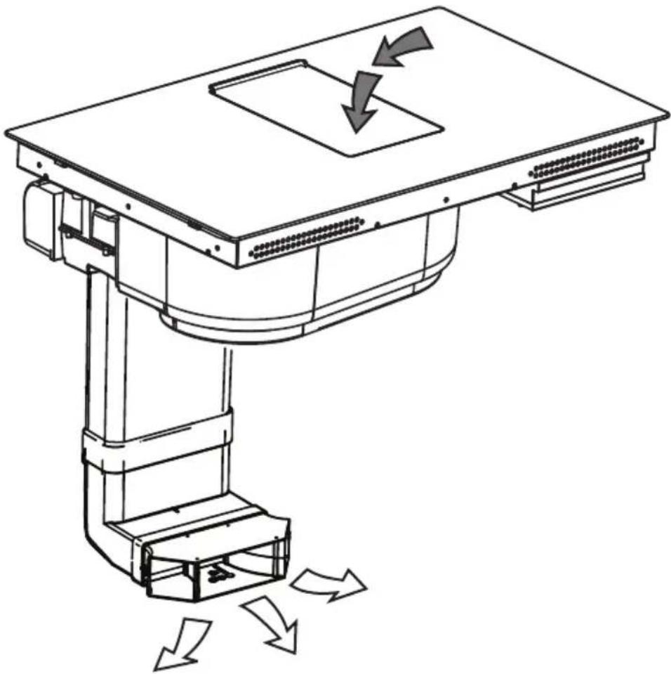
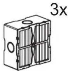
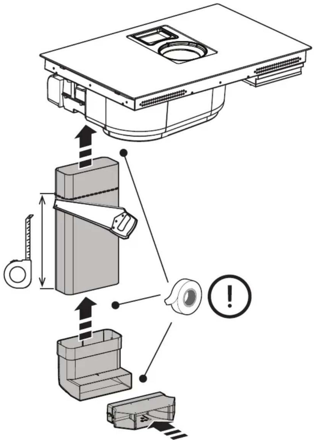
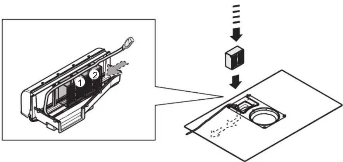
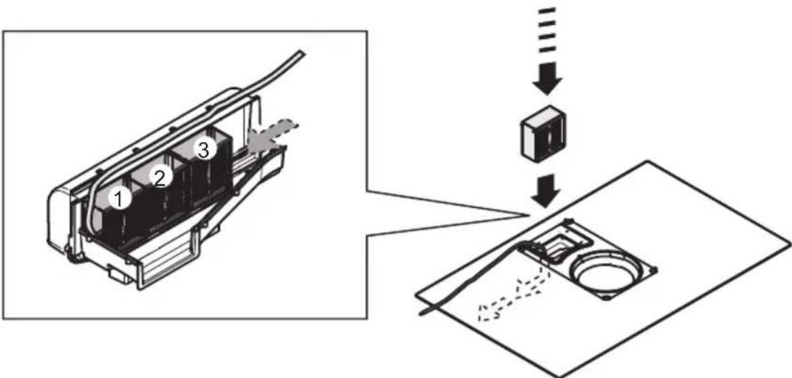
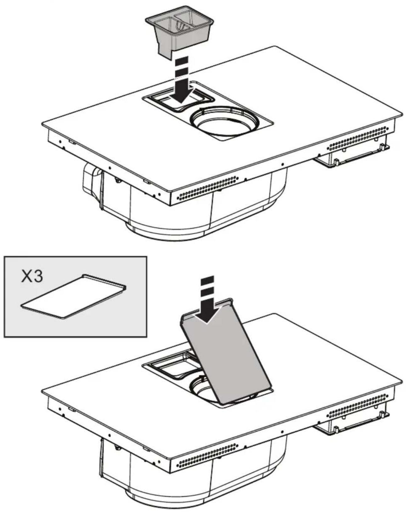
• Recirculating Version:
The extracted air will be filtered in special grease filters and odour filters before being sent back into the room. The product is supplied with all parts necessary for standard installation, with the air outlet positioned in the front part of the plinth. The product is equipped with a set of odour filters. For more information, see the page relating to accessories for the recirculating version (in the illustrated part of this manual).
RECOMMENDATIONS FOR USE
Recommendations for correct use in order to reduce the impact on the environment: When cooking begins, the device should be turned on at minimum speed, and left on for a few minutes even after cooking is complete. Increase the speed only if there is a large quantity of fumes and steam, using the Booster function only in extreme cases. To keep the odour reduction system running efficiently, replace the carbon filter/s when necessary. To ensure the high performance of the grease filter, clean it when necessary. To improve efficiency and minimise noise, use the maximum duct diameter indicated in this manual.
Make good use of the residual heat of your electric hot plate, turning it off a few minutes before cooking is complete. The base of the pot or pan should cover the entire electric hot plate; use of cookware having a smaller base than the hot plate results in a waste of energy. Cover the pots and pans with perfectly-fitting lids during cooking, and do not use more water than necessary. Cooking without positioning the lid results in much higher energy consumption. Use only flat-bottom pots and pans.
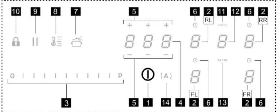
CONTROLS
CONTROL PANEL
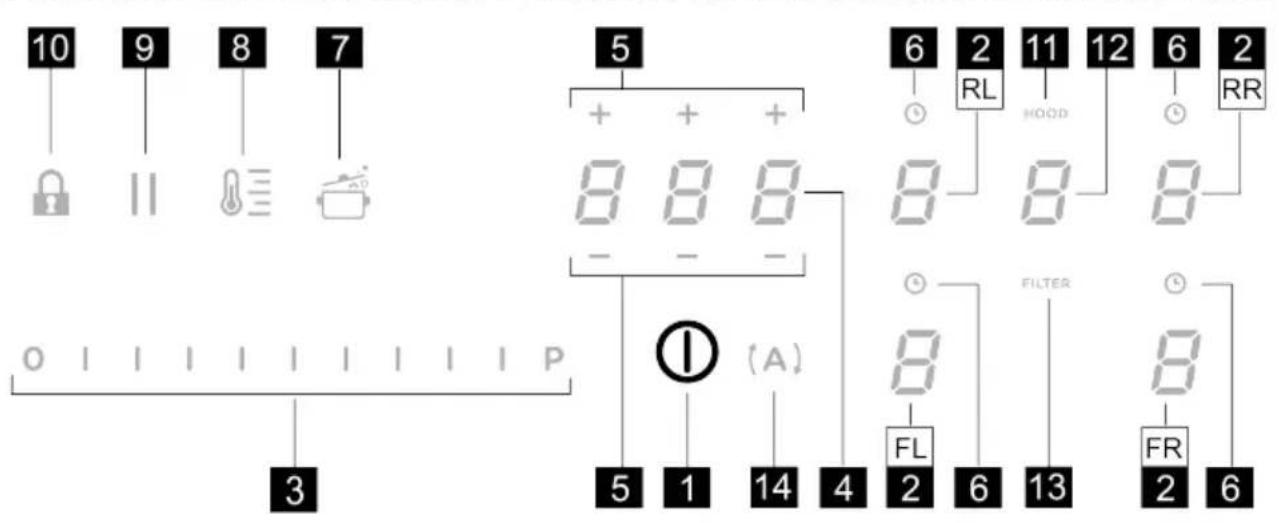
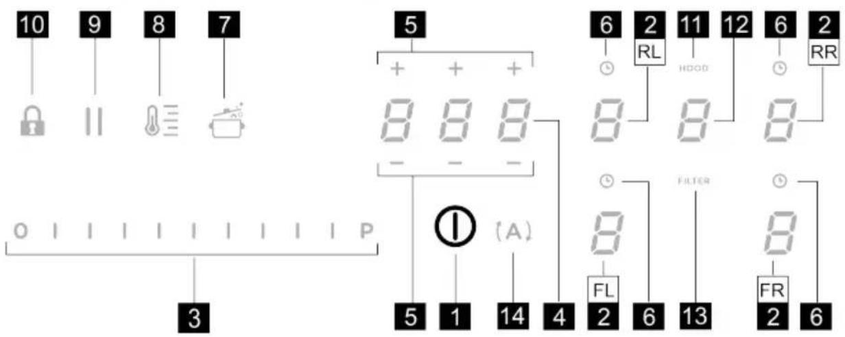
T. Function
| 1 | ON/OFF of the hob / hob extractor fan |
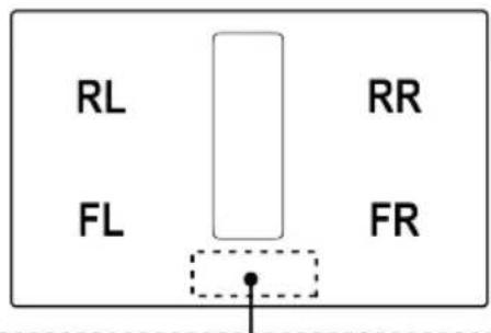
| 2 | Selection of the cooking zones / Cooking zone display |
| 3 | Increase/decrease cooking power level and extraction speed (power) |
| Display the cooking power level and extraction speed (power) | |
| 4 | Activate "STAND ALONE" timer |
| Display : "STAND ALONE" timer / Cooking Zones Timer. | |
| 5 | Increase/Decrease "STAND ALONE" Timer time / Cooking Zones timer |
| 6 | Activation of Cooking Zones Timer |
| Indicator of Cooking Zones Timer active |
| 7 | Automatic Heat Up Activation. |
| 8 | Temperature Manager activation (Warming Function) |
| 9 | Pause |
| 10 | Key Lock |
| 11 | Indicator Extractor active |
| Activation of Filter Saturation Indicator | |
| 12 | Extractor Selection/Activation |
| Extractor Display | |
| Display of Carbon/ceramic filter - Grease filter saturation | |
| 13 | Reset Filter Saturation |
| 14 | Activation of extractor automatic function |
THINGS TO KNOW BEFORE STARTING
All functions of this hob are designed to comply with the most stringent safety regulations. For this reason:
This manual describes the main functions. Use the QR code at the start of the manual to access the full instructions online. All functions of this hob comply with the most stringent safety regulations. For this reason:
- Some functions will not be activated, or will be automatically deactivated, in the absence of pots on the burners or when they are poorly positioned.
- In other cases the activated functions will be automatically deactivated after a few seconds, if the specific function requires a further setting that has not been selected (e.g.: “Turning the hob on” without “Selecting the cooking zone” and the “Operating temperature”, or the “Lock Function” or the “Timer” function).
Wait for the display to turn off before approaching the cooking zone.
Please note! In the case (for example) of prolonged use, the cooking zone may not immediately shut down because
it is in the cooling phase; the symbol will appear on the cooking zone display to indicate that this phase is under way. Wait for the display to turn off before approaching the cooking zone.
COOKING ZONE DISPLAY
The following is shown on the cooking zone displays:
| Function Value | |
| Cooking zone on | 0 |
| Power Level | 1...9-P |
| Residual Heat Indicator | 8 |
| Pot Detector | 2 |
| Bridge Zone Function active | 0 |
| Temperature Manager Function active | 4 |
| Pause function | 11 |
| Automatic Heat UP function | 8 |
CHARACTERISTICS OF THE HOB
- Safe Activation
The product is activated only in the presence of pots on the cooking zone: the heating process does not start or is interrupted if there are no pots, or if these are removed.
- Pot Detector
The product automatically detects the presence of pots on the cooking zones.
- Safety Shut Down
For safety reasons, each cooking zone has a maximum operating time, which depends on the power level set.
• Residual Heat Indicator
When switching off one or more cooking zones, the residual heat is indicated with a specific visual signal on
the display of the corresponding zone by the symbol.
USING THE HOB
Note: Before activating any functions, the desired zone must be activated
• Power-on
Briefly press (touch) ON/OFF (1) hob / extractor fan: the symbol lights up; If you continue to press: all the available functions will become visible for a few seconds, after which only the main ones will remain active; the other ones can be used, and will be activated, later, while using the device.
IMPORTANT: all the available functions will be illuminated with light intensity, which will become more intense only when they are activated.
Press again to turn off
Note: This function has priority over the others.
- Selecting the cooking zones
Briefly press (touch) the Selection/Display (2) area corresponding to the desired cooking zone.
• Power Level
The hob features 9 power levels. Touch and slide your fingers along the Selection bar (3):
to the right to increase the power level;
to the left to decrease the power level.
The power level set will be displayed in the Selection/Display area (2)
- Power Booster
The product features a supplementary power level (after level 3), which remains active for 5 minutes, after which the temperature returns to the previously set value.
Touch and slide your fingers along the Selection bar (3)
(beyond level 9) and activate the Power Booster. The Power Booster level is indicated in the Selection / Display
area (2) with the symbol

- Cooking Zone Timer
The Cooking Zone Timer function is a countdown that can be set, even simultaneously, on each cooking zone. At the end of the period set, the cooking zones switch off automatically and the user is notified with a dedicated acoustic signal.
Activation of the cooking zone timer function
- Touch (press) the Selection/Display area (2) (power level other than zero)
- Press (6) relating to the cooking zone
- Use the symbols (5) to set the duration of the Timer, which is shown in the Zone/Display (4); while
setting, the symbol (6) flashes.
Note: wait 10 seconds without pressing any other command, so that the Cooking Zone Timer will start.
Note: by pressing and holding (6) again, the cooking zone Timer is reset.
If desired, repeat the operation for several cooking zones:
Each cooking zone can have a different Timer set; in the display (4) the countdown of the cooking zone selected at that moment will appear; if no zone is selected, press the Display (4) to view the STAND-ALONE Timer countdown. When the timer has finished the countdown, an acoustic signal sounds and the cooking zone switches off.
To switch off the Timer:
- select the cooking zone (2)
- set the duration of the Timer to , using (5). - +
The countdown display mode is the same as for the STAND-ALONE Timer.
• Power Limitation
The Power Limitation function allows the product to be used while limiting its maximum absorption, adjusting the absorbed power in all active cooking zones, ensuring that the total absorbed power of the hob does not exceed the set maximum absorption level.
Note: the setting must be made with the hob switched off, without pressing the ON/OFF (1) button, when the hob is connected to the mains, or reconnected to the mains, within the next 2 minutes.
To set the Power Limitation:
- press (which will flash, only for the first 2 minutes after the product has been switched on)
- while continuing to hold down (A), press, one at a time, all the Selection/Display areas (2) of the cooking zones in a counter-clockwise direction starting from the front left zone (FR); a short acoustic signal will be emitted
with each press and when all the Displays (2) have been pressed, it will be possible to release the key:
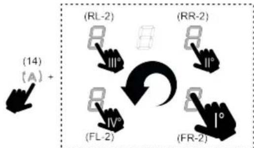
flowchart
graph TD
    A["(A)"] --> B["(RL-2)"]
    B --> C["(RR-2)"]
    C --> D["(FR-2)"]
    D --> E["(FL-2)"]
    E --> F["(IV°)"]
    F --> G["(14)"]
at this point, the Display (2) of the rear left zone (RL) will
show, in alternating sequence, the symbols and , 0 indicating that the setting can be made.
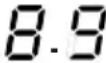
- select the Display (RL-2) then slide along the Selection
bar (3), until the Display shows the symbols and ; The Display (FL-2) will show the current setting with the values in the table:
| Displayed value | Power (Kw) |
| 7.4 Kw (default setting) | |
| 4.5 Kw | |
| 3.1 Kw |
To change the Power Limitation setting:
- press the Display (FL-2) then slide along the Selection bar (3), to
set the new setting. To save the selection made, press the ON/OFF (1) button for 2 seconds; an extended audible signal will be emitted to confirm the setting.
• Key Lock
The Key Lock allows you to lock the settings of the hob to prevent accidental tampering with the same, while leaving the set functions enabled.
Activation:
- press (30) Repeat the operation to deactivate.
Note: if any other function is pressed while the Key Lock is
active, the symbol 🔍 flash to indicate that the function is in use and must be deactivated if necessary in order to use the hob.
• Automatic Heat UP
The Automatic Heat UP function allows the set power to be reached more quickly; with this function it is possible to cook food faster without the risk of burning it, insofar as the temperature does not exceed the set level. This
function is available for power levels from to . 8 Activation:
- with the cooking zone on, press (7), the Display (2) will show a flashing /alternating with the power set in the cooking zone.
By increasing the power level of the cooking zone: the Automatic Heat Up function remains active, with the new temperature setting;
By decreasing the power level of the cooking zone: the Automatic Heat Up function is deactivated.
Note: by selecting another cooking zone at the same time, the symbol (7) will go back to being illuminated with light intensity, and it will be possible to proceed, also for this zone, with the activation of the function; in any case, the function remains active in the zone in which it has already been set, as indicated in the Display (2).
- Pause
The Pause function allows active functions on the hob to be suspended, bringing the cooking power to zero.
Activation:
- press (1), the symbol will flash on the display (2)
To deactivate the function:
- press || (9) the Selection bar (3) will light up
- press/slide on the Selection Bar (3) to deactivate the function.
Note: deactivation restores the conditions of the hob before the pause; the hob continues to work with the same settings previously set.
Note: if after 10 minutes, the Pause Function is not deactivated, the hob will turn off automatically.
Note: the Pause Function does not affect the extraction.
- "STAND ALONE" Timer
The Timer function is a countdown independent of the cooking zones (and the extraction zone).
The Timer is activated by pressing the Zone/Display (4).
Use the symbols - + (5) to set the duration of the Timer, which is shown in the Zone/Display (4)
Note: wait 10 seconds without pressing any other command, so that the countdown starts.
The Timer can be set up to a maximum of 1(h) and 59(min.) The Zone/Display (4) will show the remaining time; an acoustic signal will be emitted at the end of the countdown.
Note: When the remaining time is less than 10 minutes, a fixed dot will appear in the timer after the first number.
| Displayed value Remaining time | |
| 1.35 | 1h and 35 min |
| 1.35 | 1min. and 35 sec. |
To switch off the Timer:
- select Zone/Display (4)
- set the duration of the Timer to Zero 0.00, using - + (5)
• Temperature Manager (Warming Function)
Temperature Manager is a control function that allows the maintaining of heat at a constant temperature, at an optimised power level; ideal to keep ready-cooked foods warm. The Temperature Manager function is activated the
first time the key ⏻(8) is pressed.
The symbol □ appears in the display (2) of the zone that is working in the Temperature Manager
Note: by selecting another cooking zone at the same time,
the symbol (8) will go back to being illuminated with light intensity, and it will be possible to proceed, also for this zone, with the activation of the function; in any case, the function remains active in the zone in which it has already been set, as indicated in the Display (2).
- Press (3) again to deactivate and switch off, until the level shown in the Display (2) is brought to □.
Note: if there are several zones operating in Temperature Manager (Warming Function) mode, select the desired zone first using the Selection zone (2); the function can also be deactivated using the Selection bar (3), by bringing the Power Level to ☐.
- Bridge Zones
Thanks to the Bridge function, the cooking zones can operate in a combined way, creating a single zone with the same power level. This function allows evenly distributed cooking with large-sized pots and pans.
It is possible to use the front cooking zone in combination with the corresponding rear one (to check which zones feature this function, see the illustrated part of this manual).
To activate the Bridge Function:
- simultaneously select both cooking zones you wish to use
- the Display (2) of the “rear” cooking zone will show the symbol
• using the Selection bar (3), it will be possible to set the
operating Level (Power), which will be shown on the Display (2) of the "front" zone
To disable the Bridge Function, simply repeat the activation procedure
Note: the Cooking Zone Timer, activated during the Bridge Function, causes the automatic shut-down of both cooking zones, as in this case they are considered a single combined area.
USING THE EXTRACTOR
- Switching the extraction system on:
- Switch on the hob as indicated in the “Power-on” chapter on “using the hob”;
• Extraction speed (power):
The extractor is equipped with 3 levels of extraction speed (power).
Touch and slide your fingers along the Selection bar (3): to the right to increase the power level, to the left to decrease the power level.
Note: The set power level will be displayed in the Selection/Display area (12)
- Power Booster
The extractor fan has 2 additional power levels (beyond level 3)
Power Booster 1: timed for 15 min.
Power Booster 2: timed for 5 min.
After which the power returns to the previously set level. Touch and slide your fingers along the Selection bar (3) (past level 3), and activate the Power Booster 1, the level will be shown in the Selection/Display area (12) with the number "4" flashing.
Touch and slide your fingers along the Selection bar (3) (past level 3), and activate the Power Booster 2, the level will be shown in the Selection/Display area (12) with the symbol"

• Automatic mode
The hood will turn on at the most suitable speed, adapting the extraction capacity to the maximum cooking level used in the cooking zones.
When the cooking zones are switched off, the hood adapts its extraction speed, decreasing it gradually, to eliminate residual vapours and odours.
To activate this function:
Press (14);
Repeat the operation to deactivate.
Note: if, during automatic operation, the speeds from 1 to 3 are selected using the Selection bar (3), automatic operation is interrupted; if, on the other hand, the Power
Booster is selected, automatic operation will resume at the end of the timer and, in the meantime, the symbol (A) keeps flashing.
Note: if the hob automatically shuts down with Automatic mode active, the extractor fan will automatically turn off gradually.
• Filter saturation indicator
The hood indicates when filter maintenance is needed:
For the carbon/ceramic odour filters, FILTER (13) lights up For the grease filter, FILTER (13) lights up and flashes
Note: this function is disabled by default (see how to enable it in the paragraph "Activation of filter saturation indicator")
- Reset filter saturation
After performing maintenance on the filters (grease and/or carbon/ceramic) press and hold FILTER (13); it will turn off and the indicator counter will restart.
- Activation of filter saturation indicator
Note: This indicator is normally deactivated.
To activate it, proceed as follows:
- turn the extractor hob on;
- with the extraction motor and cooking zones off, press the Selection zone (12)
- hold HOOD (11) pressed until the Display (12) shows the letters and
0 flashing alternately.
F = carbon/ceramic odour filters; G -grease filters;
CARBON/CERAMIC ODOUR FILTERS
- press the Display (12) when the letter appears
- press FILTER (13) fixed light.
- press and hold HOOD (11) again to confirm the activation of the carbon/ceramic odour filter.
GREASE FILTER
- press the Display (12) when the letter appears
- press FILTER (13) flashing light.
- press and hold HOOD (11) again to confirm the activation of the grease filter indication.
Power level Cooking type Use (based on cooking experience and habits)
| Max power |  | Heat quickly | raises the temperature of food in a short space of time to boiling point for water, or to quickly heat cooking liquids |
 | Fry - boil | browning, starting cooking, fry frozen products, boil quickly | |
| High power | 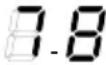 | Brown - fry - boil - grill | browning, fast rolling boil, cooking and grilling (for brief periods, 5-10 minutes) |
 | Brown - cook - stew - fry - grill | browning, slow rolling boil, cooking and grilling (for medium periods, 10-20 minutes), pre-heat accessories | |
| Medium power |  | Cook - stew - fry - grill | stewing, light rolling boil, cooking (for long periods), dressing pasta |
 | Cooking - simmering - thickening - creaming | longer cooking (rice, sauces, roasts, fish) with accompanying liquids (e.g. water, wine, stock, milk), dressing pasta | |
 | Cooking - simmering - thickening - creaming | longer cooking (volumes less than one litre: rice, sauces, roasts, fish) with accompanying liquids (e.g. water, wine, stock, milk) | |
| Low power |  | Melt - thaw - keep warm - stir | melting butter, gently melting chocolate, defrosting small products |
 | Melt - thaw - keep warm - stir | keeping small portions of just-cooked food warm or maintaining dishes at serving temperature and creaming risottos | |
| OFF |  | Support surface | Hob in stand-by or off (possible presence of residual heat from the end of cooking, signalled by H-L-O) |
MAINTENANCE
Please note! Before any cleaning or maintenance, make sure the cooking zones are switched off and the heat indicator has turned off.

For product maintenance, see the images at the end of the installation marked by this symbol.
HOB MAINTENANCE
- Cleaning the induction hob
The hob must be cleaned after each use.
Important:
- Do not use abrasive sponges, scouring pads. Their use, over time, may ruin the glass.
- Do not use irritant chemical detergents such as oven sprays or stain removers.
• DO NOT USE STEAM JET CLEANERS!!!
After each use, leave the hob to cool and clean it to remove deposits and stains caused by food residue. Sugar or food with a high sugar content damage the hob and must be removed immediately. Salt, sugar and sand may scratch the glass surface. Use a soft cloth, paper towel or specific products to clean the hob (follow the Manufacturer's instructions).
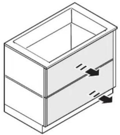
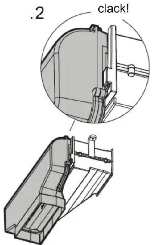
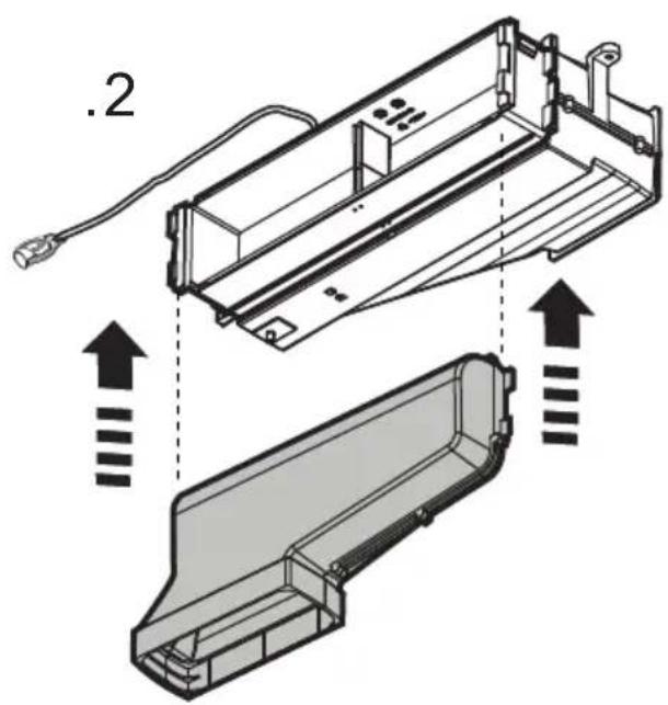
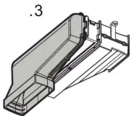
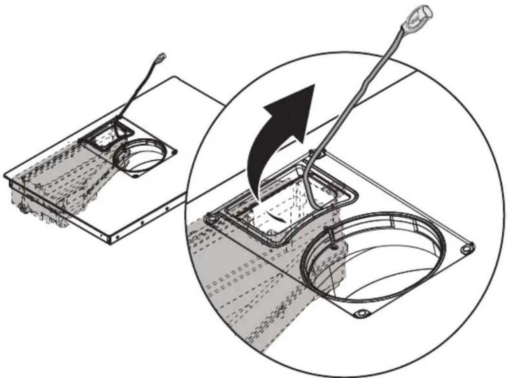
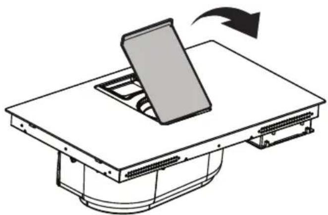
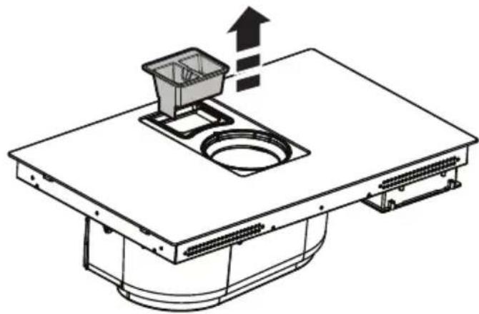
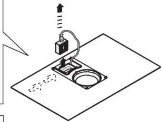
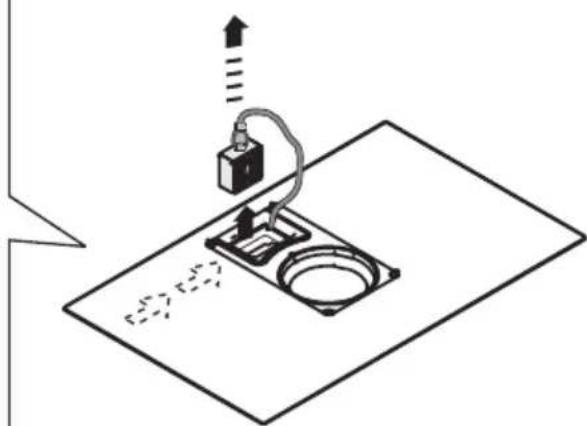
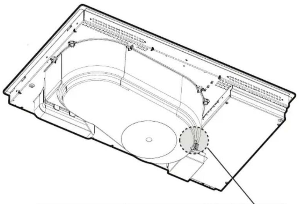
- Cleaning the liquid collection channel :
In the event large quantities of liquids accidentally spill out of the pots, they can be drained using the drain valve on the
bottom part of the product so as to eliminate any residue and ensure maximum hygiene levels.
For a more complete and in-depth clean, the bottom collection channel can be completely removed.
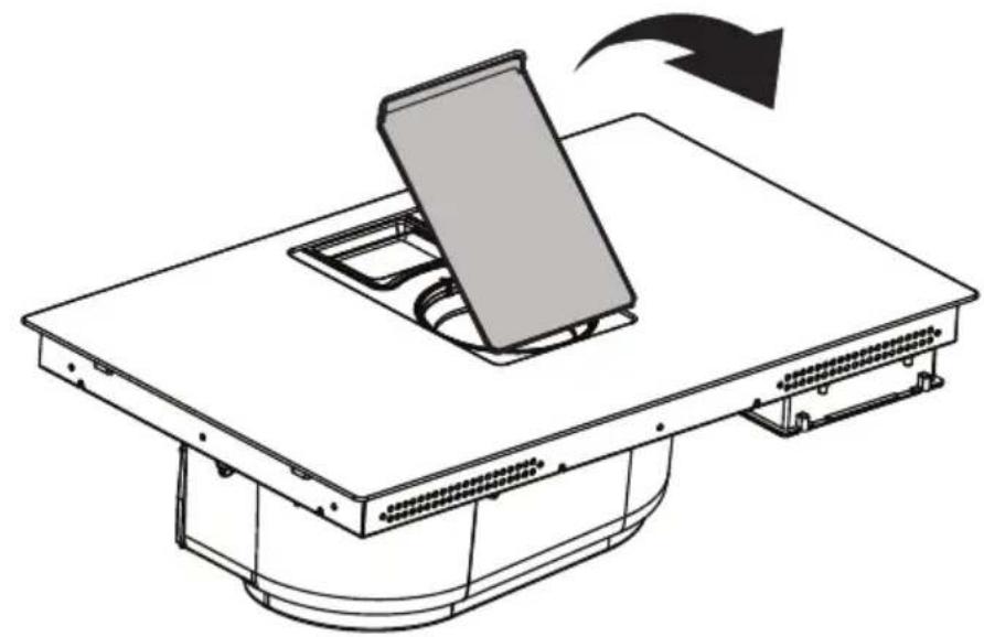
- Cleaning the metal grille:
The grille must be washed by hand with hot water and neutral detergent, then dried thoroughly to prevent oxidation.
For cleaning, use ONLY a cloth moistened with neutral liquid detergents.
DO NOT USE CLEANING UTENSILS OR TOOLS!
Avoid the use of products containing abrasives. DO NOT USE ALCOHOL!
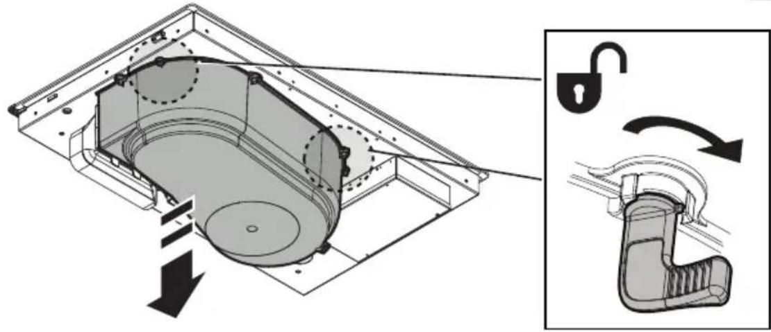
• Grease filter maintenance:
Traps grease particles generated by cooking.
Must be cleaned once a month (or when indicated by the filter saturation indication system), with non-aggressive detergents, either by hand or in the dishwasher at low temperatures and in a short cycle. When cleaned in the dishwasher, the metal grease filter may discolour, but its filtering characteristics remain unchanged.
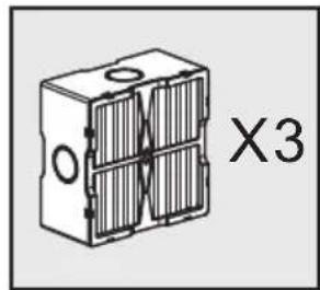
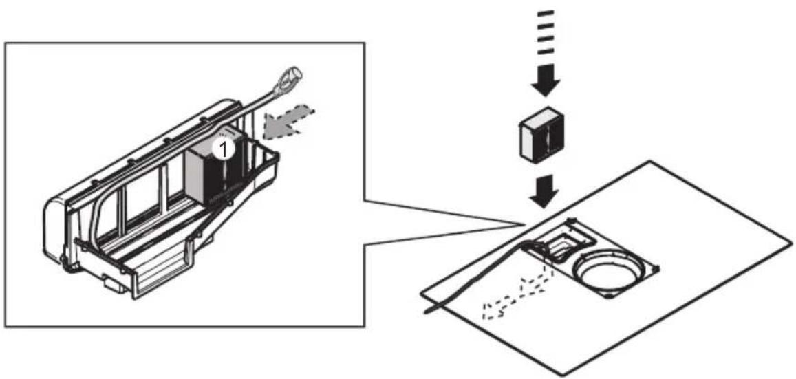
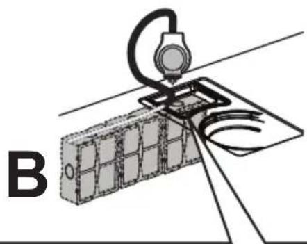
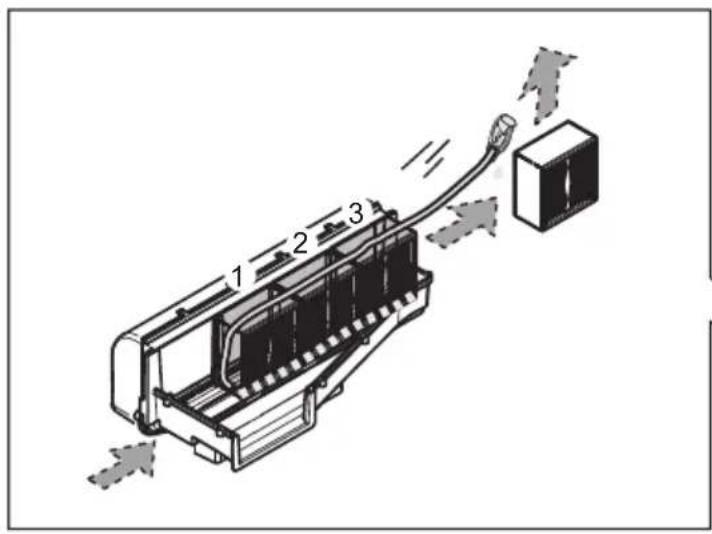
• Organic activated carbon filter maintenance (For Recirculating Version only):
Traps unpleasant odours generated by cooking. The product comes with a set of odour filters.
The saturation of the odour filters can occur after somewhat prolonged use depending on the type of cooking and how regularly the grease filter is cleaned. The odour filters can be thermally regenerated every 2/3 months in an oven preheated to 200^ C for 45 minutes. The correct regeneration of the filter ensures that it can constantly filter efficiently for 5 years.
Please note! Do not place the filters on the floor of the oven but rather in a tray, positioned at an intermediate height.
DISPOSAL
The packaging material is 100% recyclable and is marked by the recycling symbol

Make good use of the residual heat of your electric hot plate, turning it off a few minutes before cooking is complete. The base of the pot or pan should cover the entire electric hot plate; use of cookware having a smaller base than the hot plate results in a waste of energy. Cover the pots and pans with perfectly-fitting lids during cooking, and do not use more water than necessary. Cooking without positioning the lid results in much higher energy consumption. Use only flat-bottom pots and pans.
This device is marked in compliance with the European Directive 2012/19/EC - UK SI 2013 No.3113, Waste Electrical and Electronic Equipment (WEEE).
Make sure that this product is disposed of correctly. The user helps prevent potential negative consequences for the environment and for health. The symbol on the product or accompanying documentation indicates that this product should not be treated as household waste but should be handed over at a suitable collection point for the recycling of electrical and electronic equipment. Dispose of it in accordance with local regulations for waste disposal. For further information about the treatment, recovery and recycling of this product, please contact your local authority, the collection service for household waste or the shop from where the product was purchased.
Device designed, tested and developed in compliance with regulations on:
- Safety: EN/IEC 60335-1; EN/IEC 60335-2-6, EN/IEC 60335-2-31, EN/IEC 62233; • Performance: EN/IEC 61591; ISO 5167-1; ISO 5167-3; ISO 5168; EN/IEC 60704-1; EN/IEC 60704-2-13; EN/IEC 60704-3; ISO 3741; EN 50564; IEC 62301. EN 60350-2; • EMC: EN 55014-1; CISPR 14-1; EN 55014-2; CISPR 14-2; EN/IEC 61000-3-3; EN/IEC 61000-3-12. Declaration of conformity:
This appliance meets the energy label requirements of the European Commission Regulation(EU) N.65/2014 and the Ecodesign requirements of the European Commission Regulation(EU) N.66/2014 in conformity to the European standards IEC 61591 and IEC 60704-2-13. Ecodesign for Energy-Related Products and Energy Information (Amendment) (EU Exit) Regulations 2019, in compliance with the European standard IEC 60350-1.
OPERATING ERRORS
| Informative code Description | Option Possible causes Solution | ||
 | The command zone switches off due to an excessively high temperature | The temperature inside the electronic parts is too high | Wait for the hob to cool before reusing it |
 | Container unsuitable Loss of magnetic properties Remove the pot | ||
 | Communication problems between the user interface and induction module | No power supply to the module; the power cable has not been connected correctly or it is faulty | Disconnect the hob from the electrical network and check the connection |
| For all other error signals | Call customer service and report the error code | ||
TECHNICAL SPECIFICATIONS
| Height(cm) | Width(cm) | Depth(cm) |
| 22.3 83 51.5 |
CE

natural_image
Silhouette of a person pushing a shopping cart (no text or symbols)Components not supplied with product

To download the safety instructions, user manual, technical data sheet and energy data:
Visit the website docs.bauknecht.eu
Use the QR code
Alternatively, contact Customer Service (using the phone number indicated on the warranty booklet). When contacting Customer Service, communicate the codes on the product rating plate.
DE

T. Funktion
natural_image
Silhouette of a person pushing a shopping cart (no text or symbols)FR
SÉCURITÉ GÉNÉRALE
• Residual Heat Indicator
• Temperature Manager (Warming Function)
natural_image
Silhouette of a person pushing a shopping cart (no text or symbols)
NL
ALGEMENE VEILIGHEID

T. Functie
• Residual Heat Indicator
- selecteer Zone/Display (4)
- Activering indicator verzadiging filters
natural_image
Silhouette of a person pushing a shopping cart (no text or symbols)ES
SEGURIDAD GENERAL
T. Función
natural_image
Silhouette of a person pushing a shopping cart (no text or symbols)PT
SEGURANÇA GERAL
• Temperature Manager (Warming Function)
natural_image
Silhouette of a person pushing a shopping cart (no text or symbols)CS
OBECNÁ BEZPEČNOST

T. Funkce
natural_image
Silhouette of a person pushing a shopping cart (no text or symbols)ET
ÜLDINE OHUTUSTEAVE
LT
BENDROJI SAUGA

T. Veiksmas
natural_image
Silhouette of a person pushing a shopping cart (no text or symbols)Su gaminiu netiekiami komponentai
