
TK-D840H - Talkie Walkie KENWOOD - Free user manual and instructions
Find the device manual for free TK-D840H KENWOOD in PDF.
| Product Type | Dual-band mobile transceiver (digital/analog) |
| Power Supply | 12 V DC (negative ground), 15 A fuse |
| Antenna Connector | 50 Ω |
| Supplied Accessories | DC power cable, mounting bracket, screws, microphone (KMC-30 or KMC-35), microphone hanger |
| Main Functions | Scan, zone/channel, lone worker, scrambler, talk around, public address, horn alert, scrambler code |
| Display | Zone and channel number, mode indicators (Scan, Lone Worker, etc.) |
| Connections | ACC (D-SUB 15-pin), 3.5 mm speaker jack, 8-pin microphone connector, DC input |
| Safety | Explosive atmospheres, RF burns, detonators (150 m) |
| Maintenance and Cleaning | Clean with a dry, soft cloth. Do not use solvents. |
| Spare Parts and Repairability | Contact an authorized KENWOOD dealer for any repairs or spare parts. Do not disassemble yourself. |
| General Information | User manual available for download. Programming customizable by dealer. |
Frequently Asked Questions - TK-D840H KENWOOD
User questions about TK-D840H KENWOOD
0 question about this device. Answer the ones you know or ask your own.
Ask a new question about this device
Download the instructions for your Talkie Walkie in PDF format for free! Find your manual TK-D840H - KENWOOD and take your electronic device back in hand. On this page are published all the documents necessary for the use of your device. TK-D840H by KENWOOD.
USER MANUAL TK-D840H KENWOOD
text_image
S A KENWOODJVCKENWOOD Corporation
VHF DIGITAL TRANSCEIVER
TK-D740H TK-D740HV
UHF DIGITAL TRANSCEIVER
TK-D840H TK-D840HU
USER GUIDE
This User Guide covers only the basic operations of your radio. Ask your dealer for information on any customized features they may have added to your radio. For using details instruction manual (User Manual), refer to the following URL.
http://manual.kenwood.com/en_contents/search/keyword

THANK YOU
We are grateful you have chosen KENWOOD for your Digital Transceiver applications.
CONTENTS
NOTICES TO THE USER ....3
PRECAUTIONS 4
TERMINAL DESCRIPTIONS ....5
UNPACKING AND CHECKING EQUIPMENT 6
SUPPLIED ACCESSORIES 6
PREPARATION ....7
ORIENTATION 9
FRONT AND REAR VIEWS 9
DISPLAY....10
BASIC OPERATION 11
SWITCHING POWER ON/ OFF 11
ADJUSTING THE VOLUME 11
SELECTING A ZONE AND CHANNEL 11
TRANSMITTING 11
RECEIVING 11
NOTICES TO THE USER
◆ Government law prohibits the operation of unlicensed radio transmitters within the territories under government control.
◆ Illegal operation is punishable by fi ne and/or imprisonment.
◆ Refer service to qualified technicians only.
Safety: It is important that the operator is aware of, and understands, hazards common to the operation of any transceiver.

WARNING
◆ EXPLOSIVE ATMOSPHERES (GASES, DUST, FUMES, etc.)
Turn OFF your transceiver while taking on fuel or while parked in gasoline service stations. Do not carry spare fuel containers in the trunk of your vehicle if your transceiver is mounted in the trunk area.
◆ INJURY FROM RADIO FREQUENCY TRANSMISSIONS
Do not operate your transceiver when somebody is either standing near to or touching the antenna, to avoid the possibility of radio frequency burns or related physical injury.
◆ DYNAMITE BLASTING CAPS
Operating the transceiver within 500 feet (150 m) of dynamite blasting caps may cause them to explode. Turn OFF your transceiver when in an area where blasting is in progress, or where “TURN OFF TWO-WAY RADIO” signs have been posted. If you are transporting blasting caps in your vehicle, make sure they are carried in a closed metal box with a padded interior. Do not transmit while the caps are being placed into or removed from the container.
One or more of the following statements may be applicable:
FCC WARNING
This equipment generates or uses radio frequency energy. Changes or modifications to this equipment may cause harmful interference unless the modifications are expressly approved by the party responsible/ JVC KENWOOD. The user could lose the authority to operate this equipment if an unauthorized change or modification is made.
INFORMATION TO THE DIGITAL DEVICE USER REQUIRED BY THE FCC
This equipment has been tested and found to comply with the limits for a Class B digital device, pursuant to Part 15 of the FCC Rules. These limits are designed to provide reasonable protection against harmful interference in a residential installation.
This equipment generates, uses and can generate radio frequency energy and, if not installed and used in accordance with the instructions, may cause harmful interference to radio communications. However, there is no guarantee that the interference will not occur in a particular installation. If this equipment does cause harmful interference to radio or television reception, which can be determined by turning the equipment off and on, the user is encouraged to try to correct the interference by one or more of the following measures:
- Reorient or relocate the receiving antenna.
- Increase the separation between the equipment and receiver.
- Connect the equipment to an outlet on a circuit different from that to which the receiver is connected.
- Consult the dealer for technical assistance.
The AMBE+2 ^™ voice coding Technology embodied in this product is protected by intellectual property rights including patent rights, copyrights and trade secrets of Digital Voice Systems, Inc. This voice coding Technology is licensed solely for use within this Communications Equipment. The user of this Technology is explicitly prohibited from attempting to extract, remove, decompile, reverse engineer, or disassemble the Object Code, or in any other way convert the Object Code into a human-readable form. U.S. Patent Nos. #6,199,037, #6,912,495, #8,200,497, #7,970,606, and #8,359,197
Firmware Copyrights
The title to and ownership of copyrights for firmware embedded in KENWOOD product memories are reserved for JVC KENWOOD Corporation.
PRECAUTIONS
Observe the following precautions to prevent fire, personal injury, and transceiver damage.
- Do not attempt to configure the transceiver while driving; it is too dangerous.
- Do not disassemble or modify the transceiver for any reason.
- Do not expose the transceiver to long periods of direct sunlight, nor place it near heating appliances.
- If an abnormal odor or smoke is detected coming from the transceiver, switch the transceiver power off immediately, and contact your KENWOOD dealer.
- Use of the transceiver while you are driving may be against traffic laws. Please check and observe the vehicle regulations in your area.
- Do not use options not specified by KENWOOD.
- Do not put the plastic bag used for packing of this equipment on the place which reaches a small child's hand. It will become a cause of suffocation if it wears flatly.
- Do not place the transceiver on unstable surfaces.
- Keep the volume as low as possible to protect your hearing.
- Always switch the transceiver power off before installing optional accessories.

CAUTION
◆ The transceiver operates in 12 V negative ground systems only! Check the battery polarity and voltage of the vehicle before installing the transceiver.
◆ Use only the supplied DC power cable or a KENWOOD optional DC power cable.
◆ Do not cut and/or remove the fuse holder on the DC power cable.
◆ Do not place the microphone cable around your neck while near machinery that may catch the cable.

WARNING
For passenger safety, install the transceiver securely using the supplied mounting bracket and screw set so the transceiver will not break loose in the event of a collision.
TERMINAL DESCRIPTIONS
ACC (D-SUB 15 Pin Connector)
| Pin No. | Name I/O Description | Specification | ||
| 1 SB | O DC Power (Switched) | B) Output 13.6 V ±15% Max. 1 A | ||
| 2 IGN | I Ignition Signal Input | Min. Input: 10.8 VMax. Input: 16.0 V | ||
| 3 SP2 | /PA O Loudspeaker Output/ Public Address Output 4 Ω | |||
| 4 | DETO | O | RX Detected Audio Output | 280 mV _p-p (typ.) |
| 5 | DATAI | I | TX Data Input | 100 kΩ |
| 6 | FNC1/ TXD | I/O | Programmable/ PC Serial Data from Radio | High Impedance |
| 7 | FNC2/ RXD | I/O | Programmable/ PC Serial Data to Radio | High Impedance |
| 8 | FNC3 | I/O | Programmable | High Impedance |
| 9 | FNC4 | I/O | Programmable | High Impedance |
| 10 | FNC5 | I/O | Programmable | High Impedance |
| 11 | FNC6 | I/O | Programmable | High Impedance |
| 12 | 5MC | O | DC Power Output | 5 V, Max 100 mA |
| 13 | HR1 | I | Horn Alert Signal Input | Max 2 A |
| 14 | HR2 | O | Horn Alert Signal Output | Max 2 A |
| 15 | GND | — | Ground | Ground |
Speaker Jack (3.5 mm Phone Jack) 4 W/ 4 Ω
| Pin No. | Name I/O Description | $pecifi cation | ||
| 1 | SPO | O | External Speaker Output | 4 Ω |
| 3 | GND | — | Ground | Ground |
DC Input Connector
| Pin No. | Name I/O Description | Specification | |
| Red | B | I DC Power Input | 13.6 V ±15% |
| Black | GND | I Ground | Ground |
Microphone Jack
| Pin No. | Name I/O Description | $pecifi cation | ||
| 1 | MBL | O | MIC Backlight Control | High Impedance |
| 2 SB | O DC Power (Switched) | B) Output 13.6 V ±15% | ||
| 3 | GND | — | Ground | Ground |
| 4 | PTT/ TXD | I/O | PTT/ PC Serial Data from Radio | High Impedance |
| 5 | ME | — | Mic Ground | Ground |
| 6 MIC | I Mic Signal | Input | 600 Ω | |
| 7 HOOK/ RXD | I Hook/ PC | Serial Data to Radio | High Impedance | |
| 8 | DM | I/O | Mic Data Detection | High Impedance |
Antenna Terminal
50 Ω impedance
UNPACKING AND CHECKING EQUIPMENT
Note:
◆ The following instructions are for use by your KENWOOD dealer, an authorized KENWOOD service facility, or the factory.
Carefully unpack the transceiver. We recommend that you identify the items listed below before discarding the packing material. If any items are missing or have been damaged during shipment, fi le a claim with the carrier immediately.
SUPPLIED ACCESSORIES
DC power cable (with fuses) 1
- 15 A fuse .... 2
Mounting bracket 1
Screw set
- 5 x 16 mm self-tapping screw .... 4
- M4 x 6 mm hex-headed screw with washer. 4
- Spring washer .... 4
- Flat washer .... 4
Microphone (with cable)
- KMC-30
....1 - KMC-35
1 - Microphone hanger (with 4 x 16 mm self-tapping screws) .... 1
User guide 1
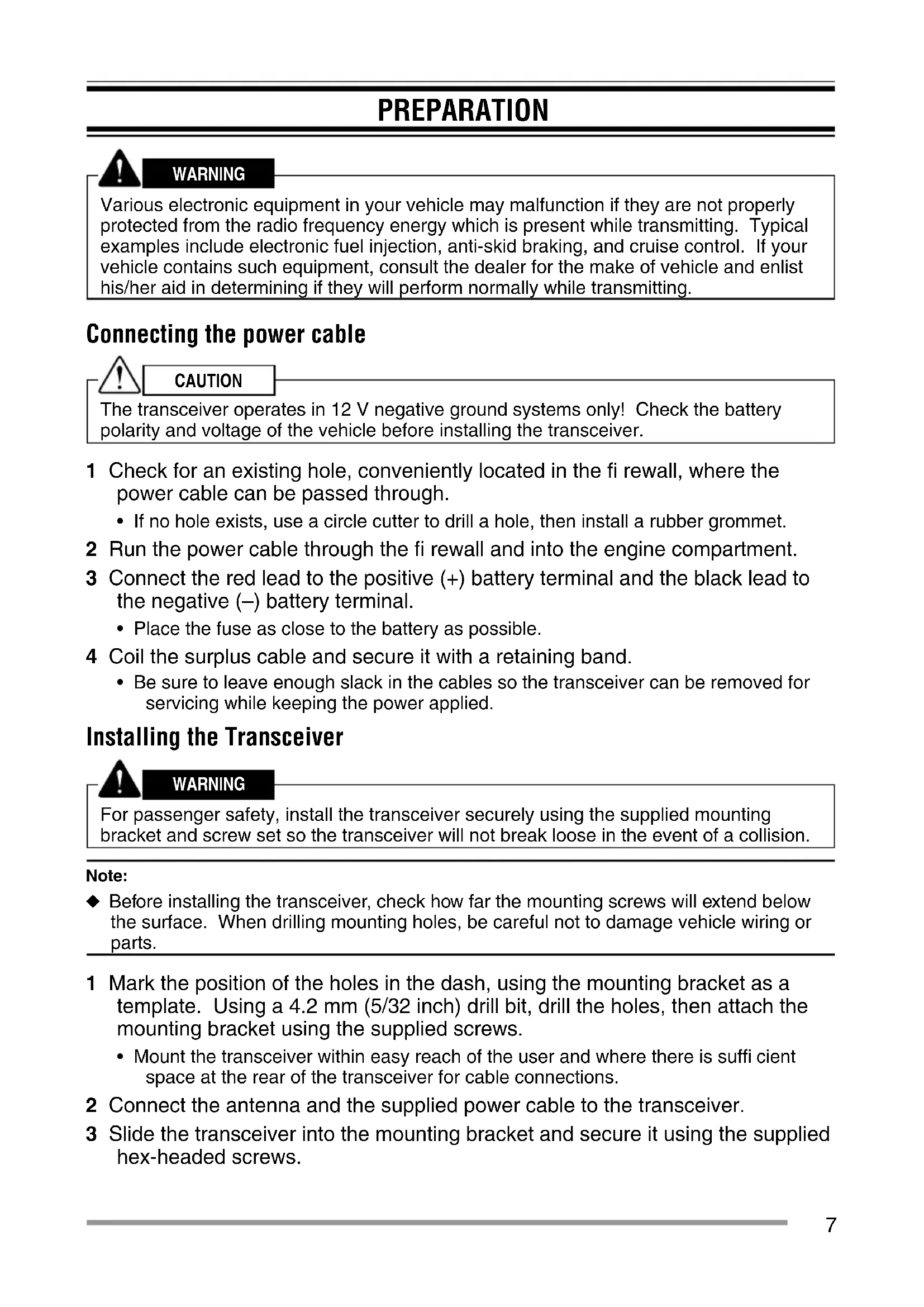
PREPARATION

WARNING
Various electronic equipment in your vehicle may malfunction if they are not properly protected from the radio frequency energy which is present while transmitting. Typical examples include electronic fuel injection, anti-skid braking, and cruise control. If your vehicle contains such equipment, consult the dealer for the make of vehicle and enlist his/her aid in determining if they will perform normally while transmitting.
Connecting the power cable

CAUTION
The transceiver operates in 12 V negative ground systems only! Check the battery polarity and voltage of the vehicle before installing the transceiver.
1 Check for an existing hole, conveniently located in the firewall, where the power cable can be passed through.
- If no hole exists, use a circle cutter to drill a hole, then install a rubber grommet.
2 Run the power cable through the fi rewall and into the engine compartment.
3 Connect the red lead to the positive (+) battery terminal and the black lead to the negative (−) battery terminal.
- Place the fuse as close to the battery as possible.
4 Coil the surplus cable and secure it with a retaining band.
- Be sure to leave enough slack in the cables so the transceiver can be removed for servicing while keeping the power applied.
Installing the Transceiver

WARNING
For passenger safety, install the transceiver securely using the supplied mounting bracket and screw set so the transceiver will not break loose in the event of a collision.
Note:
Before installing the transceiver, check how far the mounting screws will extend below the surface. When drilling mounting holes, be careful not to damage vehicle wiring or parts.
1 Mark the position of the holes in the dash, using the mounting bracket as a template. Using a 4.2 mm (5/32 inch) drill bit, drill the holes, then attach the mounting bracket using the supplied screws.
- Mount the transceiver within easy reach of the user and where there is sufficient space at the rear of the transceiver for cable connections.
2 Connect the antenna and the supplied power cable to the transceiver.
3 Slide the transceiver into the mounting bracket and secure it using the supplied hex-headed screws.
4 Mount the microphone hanger in a location where it will be within easy reach of the user.
- The microphone and microphone cable should be mounted in a place where they will not interfere with the safe operation of the vehicle.

CAUTION
When replacing the fuse in the DC power cable, be sure to replace it with a fuse of the same value. Never replace a fuse with one that is rated with a higher value.
text_image
Flat washer Spring washer M4 x 6 mm Hex-headed screw 5 x 16 mm Self-tapping screw Antenna connector Mounting bracket Power input connector Black (−) cable Red (+) cable DC power cable Fuse Microphone 12 V vehicle batteryORIENTATION
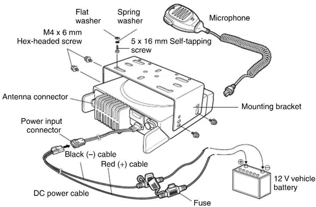
FRONT AND REAR VIEWS
text_image
1 2 3 4 8.8 S A KENood 11 12 13 ACC. SP 10 14① (Power) switch
Press to switch the transceiver ON or OFF.
② ↗ keys
Press to activate their programmable functions.
③ Display
Refer to page 10.
④ keys
Press to activate their programmable functions.
⑤ TX/RX Indicator
Lights red while transmitting. Lights green while receiving a signal. Flashes orange when receiving an optional signaling call.
⑥ Microphone jack
Insert the microphone plug into this jack.
⑦ Status Indicator
Lights during a specifi ed mode, based on dealer programming.
⑧ S / A / / △keys
Press to activate their programmable functions.
⑨ Speaker
Internal speaker.
⑩ PTT switch
Press this switch, then speak into the microphone to call a station.
⑪ Antenna connector
Connect the antenna to this connector.
⑫ ACC connector
Connect the ACC to this connector, via the KCT-60.
⑬ External speaker jack
Connect an external speaker to this jack.

Power input connector
Connect the DC Power Cable to this connector.
DISPLAY
The display shows the zone/ channel number and the 2 dots show various modes of operation.
| Display | Description Display Description | ||
 | Zone Display (Zone 1) |  | Appears when a channel is removed from the scan list. (cd) |
 | Channel Display (Channel 16) |  | Appears when the Lone Worker function is activated. (Ln) |
 | Appears during Scan. (Sc) Appears |  | ending data. (dt) |
 | Appears during the transceiver is stunned. (St) |  | Appears when the channel is busy. |
 | Appears when switch the transceiver ON.The Transceiver Password function is programmed. (PS) |  | The selected channel is the Priority channel. (P) |
 | Appears when the Squelch Level setting is activated. (SL) |  | Appears when the Scrambler function is activated. (Sr) |
 | Appears when the Talk Around function is activated. (tA) |  | Appears when the Scrambler code mode is activated. (co) |
 | Appears when the Horn Alert function is activated. (HA) |  | Appears when the Message is completed. (Ed) |
 | Appears when the Public Address function is activated. (PA) |  | Appears when the Call Interrupt function is activated. (It) |
 | Appears when the AUX function is activated. (AU) |  | Appears when the External Speaker is selected. (SP) |
 | Appears when a channel is added to the scan list. (cA) | ||
BASIC OPERATION
SWITCHING POWER ON/OFF
Press [∅] to switch the transceiver ON.
Press [⏻] again to switch the transceiver OFF.
ADJUSTING THE VOLUME
Press the key programmed as [Volume Up] to increase the volume. Press the key programmed as [Volume Down] to decrease the volume.
SELECTING A ZONE AND CHANNEL
Select the desired zone and channel using the keys programmed as [Zone Up]/[Zone Down] and [Channel Up]/[Channel Down].
- “G1” (Zone 1)/ “16” (Channel 16) appears on the display.
TRANSMITTING
1 Select the desired zone and channel.
2 Press the key programmed as [Monitor] or [Squelch Off] to check whether or not the channel is free.
- If the channel is busy, wait until it becomes free.
3 Press the PTT switch and speak into the microphone. Release the PTT switch to receive.
- For best sound quality at the receiving station, hold the microphone approximately 1.5 inches (3 cm to 4 cm) from your mouth.
RECEIVING
Select the desired zone and channel. If signaling has been programmed on the selected channel, you will hear a call only if the received signal matches your transceiver settings.
Receiving Group Calls
When you receive a group call and the received group ID matches the ID set up on your transceiver, you can hear the caller's voice.
Receiving Individual Calls
When you receive an individual call, a ringing tone will sound. To respond to the call, press and hold the PTT switch and speak into the transceiver as you would during a normal transmission.
ÉMETTEUR-RÉCEPTEUR NUMÉRIQUE VHF
TK-D740H TK-D740HV
ÉMETTEUR-RÉCEPTEUR NUMÉRIQUE UHF
TK-D840H TK-D840HU
GUIDE DE L'UTILISATEUR
MISE SOUS/ HORS TENSION 11
RÉGLAGE DU VOLUME 11
SÉLECTION D'UNE ZONE ET D'UN CANAL 11
TRANSMISSION....11
RÉCEPTION....11
AVIS AUX UTILISATEURS
Press to switch the transceiver ON or OFF.
② Touches ^/ √
Connect the antenna to this connector.
⑫ Connecteur ACC
MISE SOUS/ HORS TENSION
TRANSCEPTOR DIGITAL VHF
TK-D740H TK-D740HV
TRANSCEPTOR DIGITAL UHF
TK-D840H TK-D840HU
GUÍA DEL USUARIO
ACC (Conector D-SUB 15 pines)
text_image
Diagram of an electronic device front panel with labeled ports and connections, including a cable and power plug.© 2015 JVCKENWOOD Corporation