GSE 5500 DSG - Generator Güde - Free user manual and instructions
Find the device manual for free GSE 5500 DSG Güde in PDF.

User questions about GSE 5500 DSG Güde
0 question about this device. Answer the ones you know or ask your own.
Ask a new question about this device
Download the instructions for your Generator in PDF format for free! Find your manual GSE 5500 DSG - Güde and take your electronic device back in hand. On this page are published all the documents necessary for the use of your device. GSE 5500 DSG by Güde.
USER MANUAL GSE 5500 DSG Güde
natural_image
Icon of an open book inside a black circle (no text or symbols)natural_image
Interior view of a TOBO industrial machine with visible battery, motors, and wiring (no text or symbols on main components)Abb. 3
natural_image
Close-up of a mechanical assembly with a rotating component and directional arrow (no visible text or symbols)Abb. 5
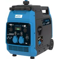
AVR (automatic voltage control to facilitate a stable output)
Generator to drive ohmic and induction appliance such as lighting chains, power hand tools (drills, chain saws, compressors). To be connected to stationary installations – heating, electric network, air conditioning – or to supply caravans – it is necessary to consult a specialised electrician.
We should not be held liable for any damage resulting from non-observance of these instructions.
Outfit (regular)
Socket with 230 V/CEE 16A 400 V 10 A protection pin, overloading fuse, oil shortage protection, transport wheels. Voltmeter

Caution! The critical point of induction appliances is the machine start up input. The input may be as much as a treble of nominal capacity. This should be always taken into account the data shown in the table are calculated values and may vary.
Guarantee
A warranty period of 12 months applies to commercial use and 24 months apply to private use and commences on the day of purchase of the device.
Warranty applies exclusively to failures due to defective material or workmanship. An original sale slip with indication of date of sale must be presented in case of claiming for the warranty rights.
Warranty does not cover unprofessional use such as device overload, violent use, damage caused by third party or foreign materials, failure to comply with operations and assembly manual, and normal wear and tear.
Scope of Delivery
GSE 5500 DSG # 40586
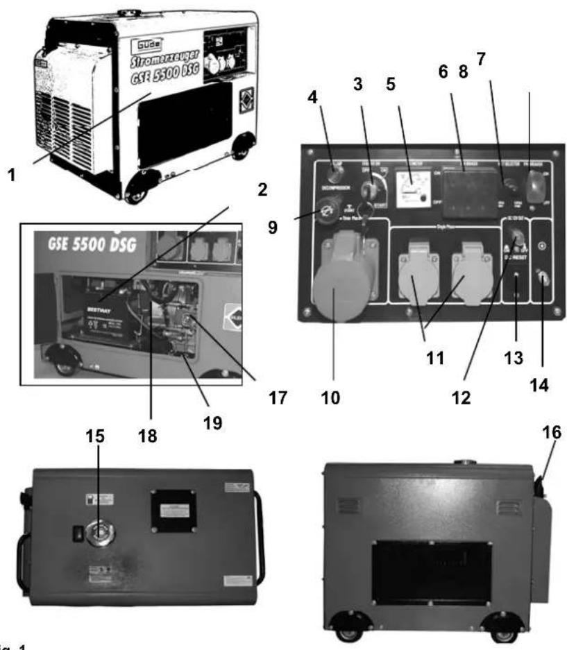
Fig. 1
- Generator
- Battery (not included in the supply – can be received in an authorised shop)
- On/off / Electric starting
- Oil replenishment plug
- Voltmeter
- Overloading protection 400 V
- 400 V / 230 V switch
- 230 V overheating fuse
- Decompression button
- 400 V CEE 16 connection
- 230 V Schuko connection
- 12 V overheating fuse
- 12 V connection
- Grounding terminal
- Tank lid
- Exhaust
- Diesel engine on/off
- Fuel tap with filter
- Earthing screw
General Safety Instructions
Prior to the initial use of the unit, the operating instructions should be read completely. If in doubt with regard to connection and operation of the unit, consult the manufacturer (servicing department).
FOLLOW THE INSTRUCTIONS BELOW CAREFULLY IN ORDER TO SECURE A HIGH DEGREE OF SAFETY:

CAUTION!
- Invite a professional electrician when connecting the generator to a house supply source to check the connection and grounding.
• Always place the generator on firm flat base! - Never use the generator in closed spaces. The flue gases may be fatal.
- Never cover up the generator.
- Never touch it with wet hands.
- Do not work in moist conditions.
- Never connect 2 generators together.
Use of the electric tools requires observance of the attached safety instructions and accessory safety instructions.

A risk of injury or damage of the electrical tool. The appliance technical data should match the safety instructions on the generator. (With start up output, 3-5 multiple of the connected unit nominal output should be observed).
Behaviour in case of emergency
Provide necessary first aid treatment corresponding to the injury nature and seek qualified medical help as soon as possible.
Protect the injured person from other injuries and calm him/her down.
First aid kit must always be available in the place of your work in case of accident in accordance with DIN 13164. Material taken out of the first aid kit needs to be supplemented right away.
If help is needed, please provide the following details:
- Place of accident
- Accident nature
- Number of injured persons
- Injury type
Signs on Unit
Meaning of Symbols
Symbols shown below are used throughout this manual and/or on the unit:
Product Safety:
 | |||||
| Product compliance with respective EU standards |
Bans:
 |  |  | |||
| General ban combined with another pictograph | No smoking, no fire, unprotected light | Do not use the unit in rain |
Warning:
 |  |  |  | ||
| Warning/Caution | Do not use the unit in closed operation spaces | Beware of health-hazardous gases | Beware of hot surface |
Commands:
 |  | ||||
| Use ear protectors | Read instruction manual carefully before use |
Environment Protection:
 |  |  | |||
| Wastes to be disposed of in a professional manner not to harm the environment. | Cardboard packaging to be collected for recycling. | Faulty and/or disposed of electrical/electronic appliances to be collected by authorised salvage places. |
Packaging:
 |  |  | |||
| Protect from moisture Keep Up Fragile | |||||
Technical Data:
 |  |  |  |  |  |
| Connection Tank volume Engine Acoustic power level Volume Weight | |||||
| IP 23 | |||||
| Protection | type | ||||
Product specific:
| Voltage automatic control | Caution!Diesel only! | Caution!Hot surface |
Assigned Use
This generator is exclusively designed for driving electric tools and machines, the maximum output of which is in rage of the generator output. The induction appliances higher start-up current must be accounted for.
The manufacturer shall not be held liable for any damage should the provision of general regulations and this instruction manual be not observed.
Residual Hazards and Protective Action
Electrical Residual Hazards
| Hazard Description Protective action Residual Hazard | |||
| Direct electrical contact Direct | contact with wet hands may result in electrical shocks | Avoid any contact with wet hands | |
Thermal Residual Hazards
| Hazard Description Protective action Residual hazard | |||
| Burns, frostbites Contact with the exhaust may result in burns. | After the operation, let the machines/tools cool down. | ||
Noise Nuisance Hazards
| Hazard Description Protective action Residual hazard | |||
| Hearing impairment Prolonged | stay in immediatevicinity of the unit may result inhearing impairment | Wear ear protectors. | |
Materials and Other Substances Hazards
| Hazard Description Protective action Residual hazard | |||
| Contact, aspiration Fumes aspiration may be fatal! Never operate in closed spaces | |||
| Fire or explosion | The unit fuel may ignite. | Never operate in the area where the fire is imminent Refuel with engine stopped. Do not smoke. | |
| Biologic / microbiologic hazard | Oil and fuel leakage is detrimental to the environment. | ||
Other Hazards
| Hazard Description Protective action Residual hazard | |||
| Damage in operation | If the unit is operated on an inclined base, lubrication is not guaranteed and the unit may get damaged | Always operate on a flat base. | |
Disposal
Disposal instructions are given by pictographs on the unit or packaging. For meaning of individual symbols refer to chapter "Symbols on Unit".
Operator Requirement
The operator shall read the instruction manual carefully before using the unit.
Qualification
No special qualification is required for use of the unit except for detailed direction by a professional.
Minimum Age
Only persons above 16 years of age are allowed to work with the unit. Exempted from the provision is the use of the juvenile trainees if they work in the course of their professional training with an aim to obtain the skill under trainer supervision.
Training
Use of the unit requires adequate lesson by a professional or the use of the manual only. Special training is not required.
Technical Data
| GSE 5500 DSG | |
| 230 V 400 V | |
| Max. output: | 4,4 kVA/3,5 kW 6,2 kVA/5,0 kW |
| Permanent output: | 4,0 kVA/3,2 kW 5,5 kVA/4,4 kW |
| Nominal voltage: | 230/400 V 1~ |
| Nominal current: | 19 A 1 ~ |
| Frequency /Protection type: | 50 Hz/IP 23 |
| Engine design: | 1-cylinder |
| Volume: | 418 ccm |
| Max. output: | 7,35 kW/10 PS |
| Fuel/ tank volume: | oil /16 l |
| Oil tank volume: | max. 1,65 l |
| Running time ca: | 7,3 h (tank volume) |
| Starting system: | Electric starter |
| Acoustic output level LWA: | 96 dB |
| Weight ca: | 141 kg |
| Dimensions L x W x H (mm): | 955 x 575 x 865 |
| Ordering No.: 40586 |
AVR (automatic voltage control)
The voltage automatic control provides for the generator voltage spikes to be within the range of values guaranteed by the power supplying company and not to expose the electronic instruments to any risk.

Caution: Check before use of the appliance its usability for operation with the generator.
Producer (HIFI, PC, TV, Camcorder, etc.) needs to be asked in advance as far as extremely sensitive electronics is concerned as the generator, due to the combustion engine, does not produce constant sinusoidal voltage.
Transportation and Storage

Caution: The unit should be operated in the working position only (flat base) since the fuel or oil could otherwise flow out and the lubrication is not guaranteed any more.
If the battery is employed, it should be taken out before any prolonged out-of-use period and stored at a safe dry place (a heated area for example).
Assembly and Initial Operation
CAUTION: The generator must be switched on for about 10 minutes every three months.
Attention, important notice: At appliances with electric starting system!

Insert a battery before you start the appliance for the first time. Appropriate battery type: 12V -
17Ah with flat pole connections, max. dimensions: w: 182 mm x h: 166,70 mm x d: 77,50 mm
ATTENTION, IMPORTANT OPERATING INSTRUCTION

You must make sure there is sufficient fuel in the generator and engine oil before every start.
Fuel pipe blow-through performed by an authorised service centre might be necessary when the fuel system is absolutely empty!
PREVENT EMPTYING OF THE FUEL TANK!
Oil Filling
As a principle, the generator is delivered without any oil in it. Check the ambient temperature and us one of oils listed below:
< 0°. SAE 10 or 10W30; 10W40
0°-25° SAE 20 or 10W30; 10W40
25°-35° SAE 30 or 10W30; 10W40
35° > SAE 40 or 10W30; 10W40
Amount of # 40586 filling: max. 1,65 l
natural_image
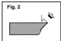
Simple line drawing of a 3D object with a small protrusion and label 'Fig. 2' (no text or symbols on the object itself)
Important notice: The generator has an oil shortage protection fitted. With a low oil level, the is impossible to be started up (when a start is attempted, the oil level indicator will light).

Always check the oil level before every use.
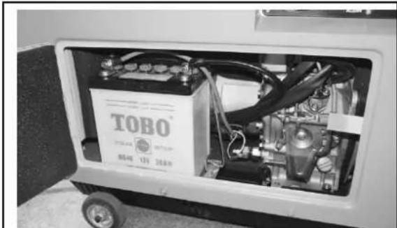
Electrical Start Battery on GSE 5500 D (# 40586) only
The battery is not included!
- Check the battery every 3 months!
- Download and check the battery in principle when removed.
- Remove the cord and insulate the contacts carefully to avoid a short circuit on.
If the generator is out of use for a longer time:
Remove the battery and store it in a safe and dry place (eg, wintering in the boiler room)
natural_image
Interior view of a TOBO industrial machine with visible battery, motors, and wiring (no readable text or symbols)Fig. 3
Refuelling
Never refuel while the unit is running. Let the unit cool down for 5 minutes at least, only then it is possible to refuel.
Fuel: Diesel

Never smoke close to the unit and fuel. Never refuel near sparkles, flames and open fire.
Important: Put away all the cables.
- Remove the cover from the filler hole.
- Pour the fuel in the filler hole carefully.
- Never fill the tank above the fuel filter upper edge.
- Place the cover back on the filler hole.
Initial Operation Safety Instructions
No sensitive electronic instruments and HI-FI, television sets, computers should be connected because of voltage spikes! These instruments could be damaged.
- Put the unit on a flat base. Do not put it on a metal base.
- Do not expose the unit to strong sunshine and temperatures above 40^ C. Do not store it in moist ambient conditions.
- Before using it, make sure that the input of the appliance to be connected to the unit is lower than the output of the generator.
- Do not connect the appliance to the generator before the later is running at full. Disconnect the appliance before switching the generator off.
- Do not connect other sources to the unit. Do not connect it to the mains.
- Immediately switch the generator off under conditions as follows:
- Unsteady or uneven engine run
- Electrical output decline
- connected appliance overheating
- Excessive generator vibrations
- Sparkling
- Smoke or fire
• Make sure that there is enough fuel before connecting the generator to the appliance - Never refuel while the unit is running. Before refuelling, let the unit cool down for 54 minutes as a minimum after any use.
- Never touch the unit hot parts.
- Do not store fuel near the unit.
- The silencer and the air filter work as flame trap. Make sure that the parts are installed correctly and in perfect condition.
Operation
Use of GSE 5500 DSG (# 40586) - Battery Starting
Make sure that no appliance is connected to the unit.
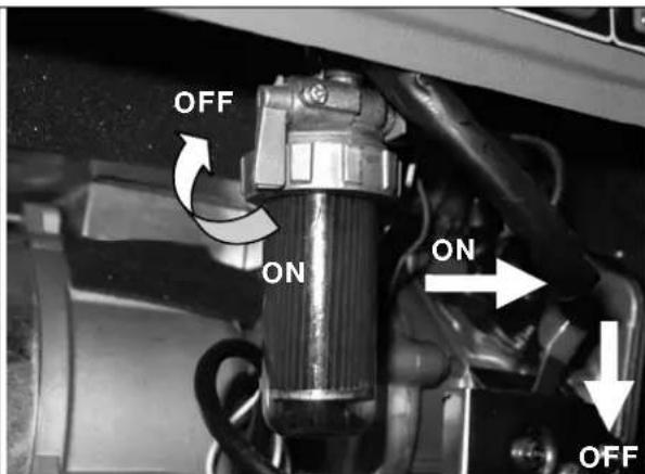
- Open the fuel cock by turning it ON
- Switch the engine by on/off.
- Turn the starting key to the "Start" position (pic. 4) and pull the decompression lever at the same time. The generator should start in a few seconds. With the ignition being on, release the decompression lever again to start the generator.

CAUTION! If the first starting attempt is unsuccessful, interrupt starting and make another attempt. Do not stay more than 5 second in the starting position!
Never remove the battery pole cable at operation. That could result in a strong electrical shock.
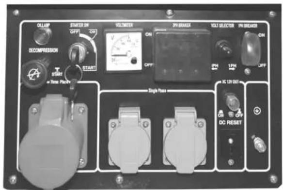
Fig. 4
If the generator is not working after several starting attempts, the oil pipeline must be manually blown through.
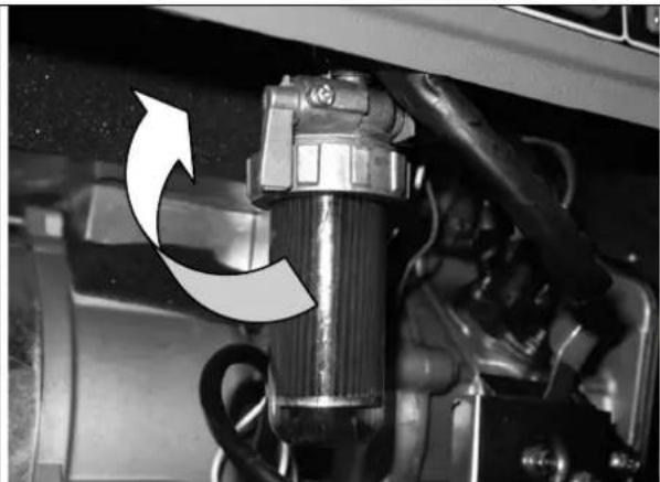
GSE 5500 DSG (#40586) Generator Turning Off
natural_image
Close-up of a mechanical assembly with a rotating component and curved arrow indicating rotation (no text or symbols visible)Fig. 5
- Disconnect the appliance from the unit before stopping the engine.
- Close the fuel tap (OFF).
- Turn the fuel cock in (OFF) position.

CAUTION! Always pill the key from the unit when the generator is out of use and keep it at a safe place. If the engine is not used for a longer period of time, it must be switched off, too.
Operator Safety Instructions
See General Safety Instructions and Initial Operation Safety Instructions.
- Do not use the machine until you have read the instruction manual carefully.
- Observe any safety instructions included in the manual.
- Be responsible to the others
Troubles – Causes – Troubleshooting
| Trouble | Cause | Troubleshooting |
| The engine will not start up. | Fuel cock closedNo fuelToo little oil in the tankAir in oil pipelineBattery too weak | Make sure that the fuel cock on/off switch are in on positionMake sure that there is enough fuel in the tank.Replenish the oilHave the oil pipeline blown throughCharge the battery with appropriate charger |
| Engine runs unevenly | Poor fuelAir in oil pipeline | Make sure that the used fuel is correct.Have the oil pipeline blown through |
| No current from generator. | Short circuitDefective cableLoose cable | If the light indicator is off, the defect is impossible to be cleared by yourself.. |
| If the light indicator is on:Press the overloading protection for the required output.Check the connection.Check whether a short circuit or overloading is not the cause. |
Inspections and Maintenance

Regular cleaning and maintenance is essential for perfect functioning and long service life of the unit.
No smoking in the course of the described jobs. Never work close to sparks, flames or open fire.
Scheduled Maintenance and Inspections
Air Filter
The air filter should be cleaned every 50 hrs of operation.
- Loosen the service cover screwing.
- Remove the cover.
- Remove the air filter.
- Clean the filter with spirit or ethanol
- Drop a small amount of oil on the air filter and compress it.
- Put the filtration cartridge back and put the housing on.
Fuel Screen
- Remove the lid from the filler hole.
- Pull the fuel screen from the filler hole.
- Clean the filter with spirit or ethanol
- Dry it with a soft cloth.
- Put the filter back in the filler.
- Replace the lid on the filler.
Oil Replacement
- Let the engine heat up.
- Unscrew the filler plug.
- Remove the discharge screw and drain the used oil into a suitable container.
- Check packing and replace it if necessary. Screw the discharge screw in and pour new oil in.
- Screw the filler neck again on.
Inspections and Maintenance Safety Instructions
The unit will serve as a sufficient aid only if maintained and cared for appropriately. Insufficient maintenance and care may result in accidents and injuries.
1.1 Inspections and Maintenance Schedule
| Time interval Description Other | details if necessary | |
| Before every use | Check the oil level | |
| After 1 month and after 6 months | Replace engine oil | |
| Every 3 months/50 hours of operation | Clean the air filter or replace it if necessary | |
| Every 6 months | Clean the fuel cock and filter, replace if necessary | |
| Every 12 months | Check the valves distance, adjust if necessary. | With the engine cooled down |
| Before every use | Check the fuel cock and hose for crack or other damages and replace if necessary | |
| Before every use | Check the exhaust system for holes, pack or replace as necessary | |
| Before very use | Check the noise silencer, clean or replace as necessary | |
| Every 12 months | Check the cooling fan | |
| Before every use | Check the Bowden starting cable, replace if necessary | |
| Every 6 months | Check screws and connecting elements and replace if necessary e | |
| Every 3 months | On battery starting units check the battery first. . | GSE 5500 D |
natural_image
Simple line drawing of a 3D object with a pointed tip and arrow, labeled 'Fig. 2' (no text or symbols on the object itself)
natural_image
Interior view of a TOBO electric vehicle battery pack with visible circuitry and wiring (no text or symbols on main body)Fig. 3
natural_image
Close-up of a mechanical assembly with a rotating component and directional arrow (no text or symbols visible)Fig. 5
natural_image
Simple line drawing of a boat with a small object on top, labeled 'Fig. 2' (no text or symbols on the boat itself)
natural_image
Interior view of a TOBO industrial machine with visible battery, motors, and wiring (no text or symbols on main components)Fig. 3
natural_image
Close-up of a mechanical component with a curved arrow indicating rotational motion (no text or symbols visible)Fig. 5
25°-35° SAE 30 of 10W30; 10W40
35^ > SAE 40 of 10W30; 10W40
natural_image
Interior view of a TOBO industrial machine with visible battery, motors, and wiring (no text or symbols on main components)natural_image
Close-up of a mechanical component with a curved arrow indicating rotation or motion (no text or symbols visible)Afb. 5
natural_image
Interior view of a TOBO electric vehicle battery pack with visible circuitry and wiring (no text or symbols on main body)Obr. 3
Doplňování paliva
natural_image
Close-up of a mechanical component with a curved arrow indicating rotational motion (no text or symbols visible)Obr. 5
natural_image
Interior view of a TOBO industrial machine with visible battery, motors, and wiring (no text or symbols on main components)Doplňovanie paliva
natural_image
Close-up of a mechanical component with a curved arrow indicating rotational motion (no text or symbols visible)Obr. 5
- Pred zastavením motora odpojte od prístroja spotrebič.
• Palivovým kohútikom otočte do polohy (OFF).
• Zavrite palivový kohút (OFF).

natural_image
Interior view of a TOBO electric vehicle battery pack with visible circuitry and wiring (no text or symbols on main body)3.ábra
Üzemanyag feltöltés
natural_image
Close-up of a mechanical component with a curved arrow indicating rotational motion (no text or symbols visible)5.ábra
natural_image
Close-up of a mechanical assembly with hoses and components, no visible text or symbols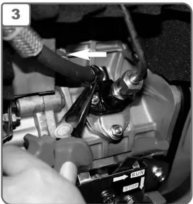
natural_image
Close-up of a mechanical assembly with visible components and a directional control switch (no text or symbols)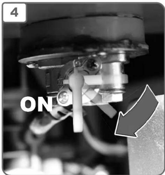


natural_image
White plastic water purifier with black handle and spool, no visible text or symbols
natural_image
Close-up of hands holding a cable with a connector, no visible text or symbols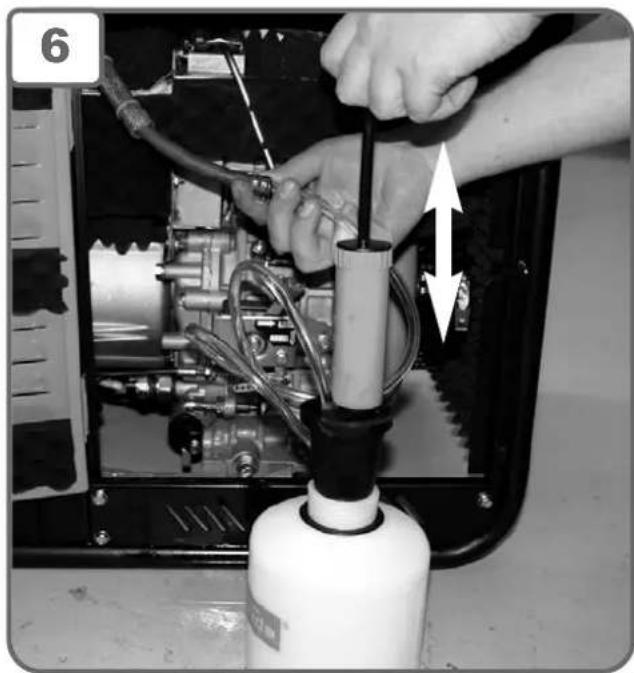
natural_image
Close-up of hands installing or adjusting a mechanical component with tubing and a bottle (no visible text or symbols)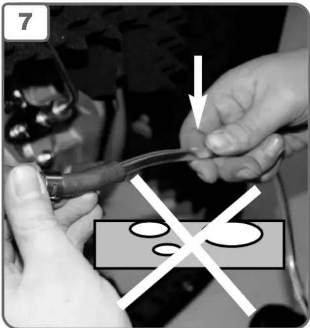

natural_image
Close-up of mechanical components with a white arrow pointing to a valve or actuator (no readable text or symbols)EC-DECLARATION OF CONFORMITY
We, hereby declare the conception and construction of the below mentioned appliances correspond - at the type of construction being launched - to appropriate basic safety and hygienic requirements of EC Directives. In case of any change to the appliance not discussed with us the Declaration expires.