
Z87 Extreme9/ac - Motherboard ASROCK - Free user manual and instructions
Find the device manual for free Z87 Extreme9/ac ASROCK in PDF.

| Product Type | ATX Motherboard |
| Socket | LGA1150 (Intel Core 4th Gen processors) |
| Chipset | Intel Z87 |
| Supported Memory | 4 x DDR3, max 32GB, up to 2933+ MHz (OC) |
| Expansion Slots | 5 x PCIe 3.0 x16, 1 x PCIe 2.0 x1, 1 x mini-PCIe |
| Integrated Graphics | HDMI, DisplayPort/Thunderbolt, triple monitor, 4K |
| Audio | Realtek ALC1150 7.1-channel HD, Purity Sound 115dB SNR DAC |
| Network | 2 x Intel Gigabit LAN, Wi-Fi 802.11ac (dual-band), Bluetooth 4.0 |
| Storage | 10 x SATA3 6Gb/s (6 Intel + 4 ASMedia), 1 x eSATA |
| USB | 6 x USB 3.0, 6 x USB 2.0 |
| Required Power | 24-pin ATX, 2 x 8-pin 12V |
| BIOS | Dual UEFI AMI 64Mb, BIOS selector |
| Dimensions (L x W) | 305 x 244 mm |
| Approximate Weight | 1.2 kg |
| Key Features | Supports up to 4-way SLI/CrossFire, Thunderbolt, Home Cloud, BCLK overclocking |
| Maintenance and Cleaning | Clean with a dry, lint-free cloth; avoid moisture |
| Safety | Dual BIOS for backup, Clear CMOS button/jumper, ESD protection |
| Spare Parts and Repairability | Contact ASRock support or an authorized reseller for replacement parts |
| General Information | Premium Japanese capacitors, Digi Power design, ASRock warranty |
Frequently Asked Questions - Z87 Extreme9/ac ASROCK
User questions about Z87 Extreme9/ac ASROCK
0 question about this device. Answer the ones you know or ask your own.
Ask a new question about this device
Download the instructions for your Motherboard in PDF format for free! Find your manual Z87 Extreme9/ac - ASROCK and take your electronic device back in hand. On this page are published all the documents necessary for the use of your device. Z87 Extreme9/ac by ASROCK.
USER MANUAL Z87 Extreme9/ac ASROCK
Copyright©2013 ASRock INC. All rights reserved.
Copyright Notice:
No part of this documentation may be reproduced, transcribed, transmitted, or translated in any language, in any form or by any means, except duplication of documentation by the purchaser for backup purpose, without written consent of ASRock Inc.
Products and corporate names appearing in this documentation may or may not be registered trademarks or copyrights of their respective companies, and are used only for identification or explanation and to the owners' benefit, without intent to infringe.
Disclaimer:
Specifications and information contained in this documentation are furnished for informational use only and subject to change without notice, and should not be constructed as a commitment by ASRock. ASRock assumes no responsibility for any errors or omissions that may appear in this documentation.
With respect to the contents of this documentation, ASRock does not provide warranty of any kind, either expressed or implied, including but not limited to the implied warranties or conditions of merchantability or fitness for a particular purpose.
In no event shall ASRock, its directors, officers, employees, or agents be liable for any indirect, special, incidental, or consequential damages (including damages for loss of profits, loss of business, loss of data, interruption of business and the like), even if ASRock has been advised of the possibility of such damages arising from any defect or error in the documentation or product.

This device complies with Part 15 of the FCC Rules. Operation is subject to the following two conditions:
(1) this device may not cause harmful interference, and
(2) this device must accept any interference received, including interference that may cause undesired operation.
CALIFORNIA, USA ONLY
The Lithium battery adopted on this motherboard contains Perchlorate, a toxic substance controlled in Perchlorate Best Management Practices (BMP) regulations passed by the California Legislature. When you discard the Lithium battery in California, USA, please follow the related regulations in advance.
"Perchlorate Material-special handling may apply, see www.dtsc.ca.gov/hazardouswaste/perchlorate"
ASRock Website: http://www.asrock.com

The terms HDMI ^™ and HDMI High-Definition Multimedia Interface, and the HDMI logo are trademarks or registered trademarks of HDMI Licensing LLC in the United States and other countries.

Manufactured under license under U.S. Patent Nos: 5,956,674; 5,974,380; 6,487,535; 7,003,467 & other U.S. and worldwide patents issued & pending. DTS, the Symbol, & DTS and the Symbol together is a registered trademark & DTS Connect, DTS Interactive, DTS Neo:PC are trademarks of DTS, Inc. Product includes software.
© DTS, Inc., All Rights Reserved.


Connect


Interactive

Neo:PC
Motherboard Layout
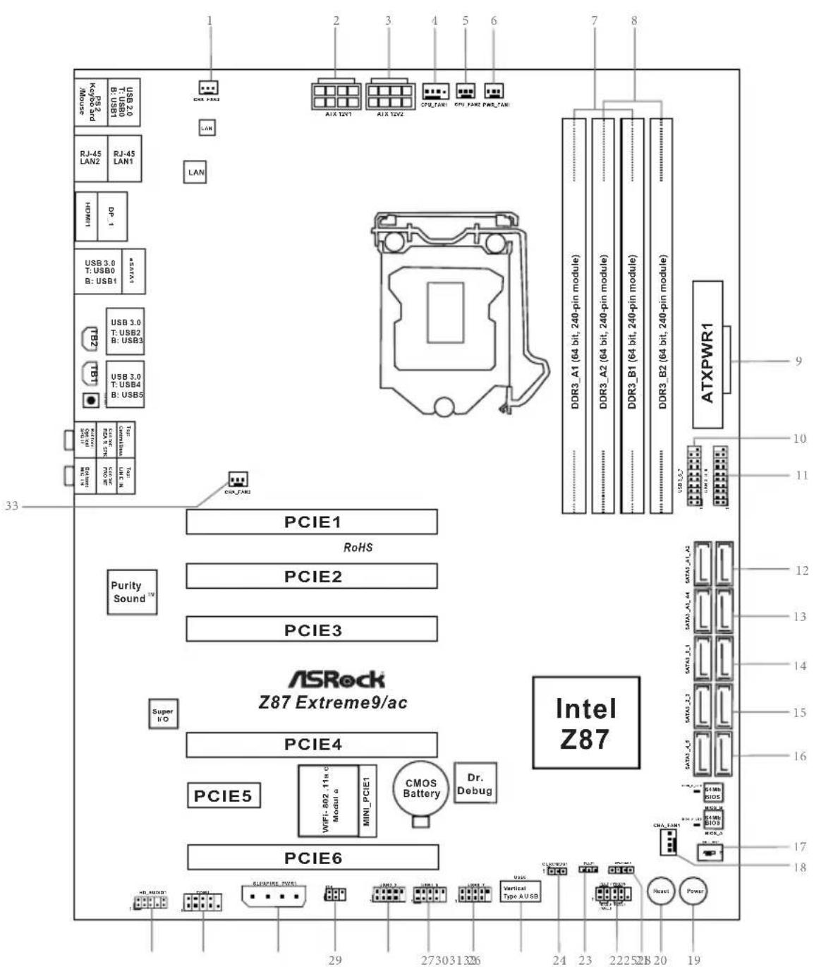
No. Description
| 1 Chassis Fan Connector (CHA_FAN3) |
| 2 ATX 12V Power Connector (ATX12V1) |
| 3 ATX 12V Power Connector (ATX12V2) |
| 4 CPU Fan Connector (CPU_FAN1) |
| 5 CPU Fan Connector (CPU_FAN2) |
| 6 Power Fan Connector (PWR_FAN1) |
| 7 2 x 240-pin DDR3 DIMM Slots (DDR3_A1, DDR3_B1) |
| 8 2 x 240-pin DDR3 DIMM Slots (DDR3_A2, DDR3_B2) |
| 9 ATX Power Connector (ATXPWR1) |
| 10 USB 3.0 Header (USB3_6_7) (ASMedia Hub) |
| 11 USB 3.0 Header (USB3_8_9) (ASMedia Hub) |
| 12 SATA3 Connectors (SATA3_A1_A2) |
| 13 SATA3 Connectors (SATA3_A3_A4) |
| 14 SATA3 Connectors (SATA3_0_1) |
| 15 SATA3 Connectors (SATA3_2_3) |
| 16 SATA3 Connectors (SATA3_4_5) |
| 17 BIOS Selection Switch (BIOS_SEL1) |
| 18 Chassis Fan Connector (CHA_FAN1) |
| 19 Power Switch (PWRBTN1) |
| 20 Reset Switch (RSTBTN1) |
| 21 Chassis Speaker Header (SPEAKER1) |
| 22 System Panel Header (PANEL1) |
| 23 Power LED Header (PLED1) |
| 24 Clear CMOS Jumper (CLRCMOS1) |
| 25 Vertical Type A USB 2.0 (USB8) |
| 26 USB 2.0 Header (USB_6_7) |
| 27 USB 2.0 Header (USB4_5) |
| 28 USB 2.0 Header (USB2_3) |
| 29 Infrared Module Header (IR1) |
| 30 SLI/XFIRE Power Connector (SLI/XFIRE_PWR1) |
| 31 COM Port Header (COM1) |
| 32 Front Panel Audio Header (HD_AUDIO1) |
| 33 Chassis Fan Connector (CHA_FAN2) |
* There are two LEDs on each LAN port. Please refer to the table below for the LAN port LED indications.
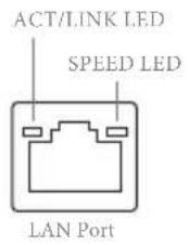
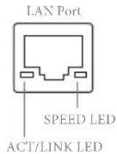
| Activity / Link LED Speed LED | |||
| Status Description Status Description | |||
| Off No Link Off | 10Mbps connection | ||
| Blinking | Data Activity | Orange | 100Mbps connection |
| On Link Green | Gbps connection | ||
** If you use a 2-channel speaker, please connect the speaker's plug into "Front Speaker Jack". See the table below for connection details in accordance with the type of speaker you use.
| Audio Output Channels | Front Speaker (No. 10) | Rear Speaker (No. 8) | Central / Bass (No. 7) | Line In (No. 9) |
| 2 V -- -- -- | ||||
| 4 V V -- -- | ||||
| 6 V V V -- | ||||
| 8 V V V V |

To enable Multi-Streaming, you need to connect a front panel audio cable to the front panel audio header. After restarting your computer, you will find the "Mixer" tool on your system. Please select "Mixer ToolBox", click "Enable playback multi-streaming", and click "ok". Choose "2CH", "4CH", "6CH", or "8CH" and then you are allowed to select "Realtek HDA Primary output" to use the Rear Speaker, Central/Bass, and Front Speaker, or select "Realtek HDA Audio 2nd output" to use the front panel audio.
*** The eSATA connector supports SATA with cables within 1 meters.
I/O Panel
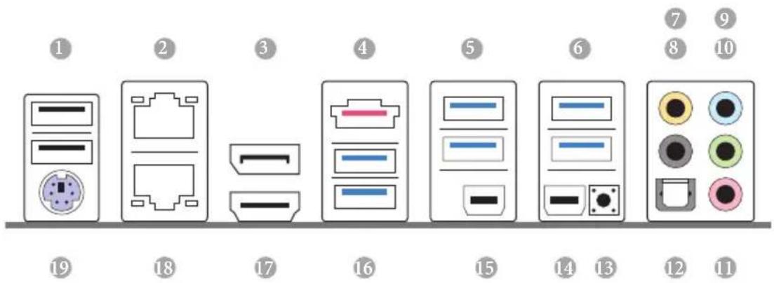
No. Description No. Description
| 1 USB 2.0 Ports (USB01) 11 Microphone (Pink) | |
| 2 LAN RJ-45 Port (Intel® I211AT)* 12 Optical SPDIF Out Port | |
| 3 Display Port Input (HDMI_DP_1) 13 | Clear CMOS Button |
| 4 eSATA Connector*** | 14 Thunderbolt Port (TBT1) |
| 5 USB 3.0 Ports (USB3_23) 15 Thunderbolt Port (TBT2)(ASMedia Hub) 16 USB 3.0 Ports (USB3_01) | |
| 6 USB 3.0 Ports (USB3_45) | (ASMedia Hub) |
| 7 Central / Bass (Orange) | 17 HDMI Port |
| 8 Rear Speaker (Black) | 18 LAN RJ-45 Port (Intel® I217V)* |
| 9 Line In (Light Blue) | 19 PS/2 Mouse/Keyboard Port |
| 10 Front Speaker (Lime)** | |
Chapter 1 Introduction
Thank you for purchasing ASRock Z87 Extreme9/ac motherboard, a reliable motherboard produced under ASRock's consistently stringent quality control. It delivers excellent performance with robust design conforming to ASRock's commitment to quality and endurance.

Because the motherboard specifications and the BIOS software might be updated, the content of this documentation will be subject to change without notice. In case any modifications of this documentation occur, the updated version will be available on ASRock's website without further notice. If you require technical support related to this motherboard, please visit our website for specific information about the model you are using. You may find the latest VGA cards and CPU support list on ASRock's website as well. ASRock website http://www.asrock.com.
1.1 Package Contents
ASRock Z87 Extreme9/ac Motherboard (ATX Form Factor)
ASRock Z87 Extreme9/ac Quick Installation Guide
ASRock Z87 Extreme9/ac Support CD
10 x Serial ATA (SATA) Data Cables (Optional)
1 x I/O Panel Shield
2 x ASRock SLI_Bridge Cards
1 x ASRock SLI_Bridge_3S Card
1 x ASRock 3-Way SLI Bridge Card
1 x ASRock Wi-SD Box
12 Screws (for Wi-SD Box)
1 x USB 3.0 Cable
1.2 Specifications
| Platform | ATX Form FactorPremium Gold Capacitor design (100% Japan-made high-quality Conductive Polymer Capacitors)Multiple Filter Cap (MFC) (Filter different noise by 3 different capacitors: DIP solid cap, POSCAP and MLCC) |
| A-Style | Home CloudPurity SoundTM802.11ac WiFi |
| CPU | Socket LGA1150 to support 4thGen Intel® CoreTM ProcessorDigi Power Design12 Power Phase DesignDual-Stack MOSFET (DSM)Supports Intel® Turbo Boost 2.0 TechnologySupports Intel® K-Series unlocked CPUSupportsASRock BCLK Full-range Overclocking |
| Chipset | Intel® Z87 |
| Memory | Dual Channel DDR3 Memory Technology4 x DDR3 DIMM slotsSupports DDR3 2933+(OC)/2800(OC)/2400(OC)/2133(OC)/1866(OC)/1600/1333/1066 non-ECC, un-buffered memoryMax. capacity of system memory: 32GB(see CAUTION)Supports Intel® Extreme Memory Profile (XMP)1.3/1.2Distortion-Free Slot |
Expansion Slot
5 x PCI Express 3.0 x16 slots (PCIE1/PCIE2/PCIE3/PCIE4/PCIE6: single at x16 (PCIE2); dual at x16 (PCIE1) / x16 (PCIE4); triple at x8 (PCIE1) / x8 (PCIE3) / x16 (PCIE4); quad at x8 (PCIE1) / x8 (PCIE3) / x8 (PCIE4) / x8 (PCIE6)) * PCIE1, PCIE3, PCIE4 and PCIE6 slots will be disabled if PCIE2 slot is occupied. 1 x PCI Express 2.0 x1 slot 1 x mini-PCI Express slot: For WiFi + BT module PLX PEX 8747 and PLX PEX 8608 embedded Supports AMD Quad CrossFireX ^TM , 4-Way CrossFireX ^TM , 3-Way CrossFireX ^TM and CrossFireX ^TM Supports NVIDIA ^TM Quad SLI ^TM , 4-Way SLI ^TM , 3-Way SLI ^TM and SLI ^TM
Graphics
Intel® HD Graphics Built-in Visuals and the VGA outputs can be supported only with processors which are GPU integrated. Supports Intel® HD Graphics Built-in Visuals : Intel® Quick Sync Video with AVC, MVC (S3D) and MPEG-2 Full HW Encode1, Intel® InTruTM 3D, Intel® Clear Video HD Technology, Intel® InsiderTM, Intel® HD Graphics 4400/4600 Pixel Shader 5.0, DirectX 11.1 Max. shared memory 1792MB Two VGA Output options: HDMI and DisplayPort/ Thunderbolt ports Supports Triple Monitors Supports HDMI Technology with max. resolution up to 4K × 2K (4096x2304) @ 24Hz Supports DisplayPort/Thunderbolt with max. resolution up to 4K x 2K (4096x2304) @ 24Hz Supports Auto Lip Sync, Deep Color (12bpc), xvYCC and HBR (High Bit Rate Audio) with HDMI (Compliant HDMI monitor is required) Supports HDCP function with HDMI and DisplayPort/ Thunderbolt ports Supports Full HD 1080p Blu-ray (BD) playback with HDMI and DisplayPort/Thunderbolt ports Supports data transfer rate up to 10Gbps with Thunderbolt port Supports Daisy-chain up to 6 Thunderbolt devices
| Audio | 7.1 CH HD Audio with Content Protection (Realtek ALC1150 Audio Codec)Premium Blu-ray audio supportSupports Purity SoundTM- 115dB SNR DAC with differential amplifier-TI® NE5532 Premium Headset Amplifier (supports up to 600 Ohms headsets)- Direct Drive Technology- EMI shielding cover- PCB isolate shieldingSupports DTS Connect |
| LAN | Gigabit LAN 10/100/1000 Mb/s1 x Giga PHY Intel® I217V, 1 x GigaLAN Intel® I211ATSupports Intel® Remote Wake Technology (on Intel® I217V)Supports Wake-On-LANSupports Dual LAN with TeamingSupports Energy Efficient Ethernet 802.3azSupports PXE |
| Wireless LAN | Supports IEEE 802.11a/b/g/n/acSupports Dual-Band (2.4/5 GHz)Supports High speed wireless connection up to 867Mbps2 antennas to support 2 (Transmit) x 2 (Receive) diversity technologySupports Bluetooth 4.0 / 3.0 + High speed class II |
| Rear Panel I/O | 1 x PS/2 Mouse/Keyboard Port1 x HDMI Port1 x DisplayPort Input for Thunderbolt port (TBT1 for test only)2 x Thunderbolt Ports (support Thunderbolt devices or DisplayPort Monitors)1 x Optical SPDIF Out Port1 x eSATA Connector2 x USB 2.0 Ports6 x USB 3.0 Ports2 x RJ-45 LAN Ports with LED (ACT/LINK LED and SPEED LED)1 x Clear CMOS SwitchHD Audio Jack: Rear Speaker / Central / Bass / Line in / Front Speaker / Microphone |
Storage
6 x SATA3 6.0 Gb/s connectors by Intel® Z87, support RAID (RAID 0, RAID 1, RAID 5, RAID 10, Intel Rapid Storage Technology 12 and Intel Smart Response Technology), NCQ, AHCI and Hot Plug
4 x SATA3 6.0 Gb/s connectors by ASMedia ASM1061, support NCQ, AHCI and Hot Plug (SATA3_A4 connector is shared with the eSATA port)
1 x eSATA connector by ASMedia ASM1061, supports NCQ, AHCI, Hot Plug and Port Multiplier
Connector
1 x IR header
1 x COM port header
1 x Power LED header
2 x CPU Fan connectors (1 x 4-pin, 1 x 3-pin)
3 x Chassis Fan connectors (1 x 4-pin, 2 x 3-pin)
1 x Power Fan connector (3-pin)
1 x 24 pin ATX power connector
2 x 8 pin 12V power connectors
(Hi-Density Power Connectors)
1 x SLI/XFire power connector
1 x Front panel audio connector
3 x USB 2.0 headers (support 6 USB 2.0 ports)
1 x Vertical Type A USB 2.0
2 x USB 3.0 headers (support 6 USB 3.0 ports)
* Wi-SD Box installation is required to support 6 USB3.0 ports.
1 x Dr. Debug with LED
1 x Power Switch with LED
1 x Reset Switch with LED
1 x BIOS Selection Switch
BIOS
2 x 64Mb AMI UEFI Legal BIOS with Multilingual GUI support (1 x Main BIOS and 1 x Backup BIOS)
Feature
Supports Secure Backup UEFI Technology
ACPI 1.1 Compliance Wake Up Events
SMBIOS 2.3.1 Support
CPU, DRAM, PCH 1.05V, PCH 1.5V Voltage Multi-adjustment
| Support CD | Drivers, Utilities, AntiVirus Software (Trial Version), Cyber-Link MediaEspresso 6.5 Trial, Google Chrome Browser and Toolbar, Start8, MeshCentral, Splashtop Streamer |
| Hardware | CPU/Chassis Temperature SensingCPU/Chassis/Power Fan TachometerCPU/Chassis Quiet Fan (Allow Chassis Fan Speed Auto-Adjust by CPU Temperature)CPU/Chassis Fan Multi-Speed ControlVoltage Monitoring: +12V, +5V, +3.3V, CPU Vcore |
| OS | Microsoft® Windows® 8 / 8 64-bit / 7 / 7 64-bit compliant |
| Certifications | FCC, CE, WHQLErP/EuP Ready (ErP/EuP ready power supply is required) |
* For detailed product information, please visit our website: http://www.asrock.com

Please realize that there is a certain risk involved with overclocking, including adjusting the setting in the BIOS, applying Untied Overclocking Technology, or using third-party overclocking tools. Overclocking may affect your system's stability, or even cause damage to the components and devices of your system. It should be done at your own risk and expense. We are not responsible for possible damage caused by overclocking.

Due to limitation, the actual memory size may be less than 4GB for the reservation for system usage under Windows ^® 32-bit operating systems. Windows ^® 64-bit operating systems do not have such limitations. You can use ASRock XFast RAM to utilize the memory that Windows ^® cannot use.
1.3 Unique Features

ASRock A-Tuning
A-Tuning is ASRock's multi purpose software suite with a new interface, more new features and improved utilities, including XFast RAM, Dehumidifier, Good Night LED, FAN-Tastic Tuning, OC Tweaker and a whole lot more.

ASRock Instant Flash
ASRock Instant Flash is a BIOS flash utility embedded in Flash ROM. This convenient BIOS update tool allows you to update the system BIOS in a few clicks without preparing an additional floppy diskette or other complicated flash utility. Just save the new BIOS file to your USB storage and launch this tool by pressing

ASRock APP Charger
Simply by installing the ASRock APP Charger makes your iPhone/iPad/iPod Touch charge up to 40% faster than before on your computer. ASRock APP Charger allows you to quickly charge many Apple devices simultaneously and even supports continuous charging when your PC enters into Standby mode (S1), Suspend to RAM (S3), hibernation mode (S4) or power off (S5).

ASRock XFast USB
ASRock XFast USB can boost the performance of your USB storage devices. The performance may depend on the properties of the device.

ASRock XFast LAN
ASRock XFast LAN provides faster internet access, which includes the benefits listed below. LAN Application Prioritization: You can configure your application's priority ideally and add new programs to the list. Lower Latency in Game: After setting online game's priority higher, it can lower the latency in games. Traffic Shaping: You can watch Youtube HD videos and download simultaneously. Real-Time Analysis of Your Data: With the status window, you can easily recognize which data streams you are currently transferring.

ASRock XFast RAM
ASRock XFast RAM is included in A-Tuning. It fully utilizes the memory space that cannot be used under Windows ^® 32-bit operating systems. ASRock XFast RAM shortens the loading time of previously visited websites, making web surfing faster than ever. And it also boosts the speed of Adobe Photoshop 5 times faster. Another advantage of ASRock XFast RAM is that it reduces the frequency of accessing your SSDs or HDDs in order to extend their lifespan.

ASRock Crashless BIOS
ASRock Crashless BIOS allows users to update their BIOS without fear of failing. If power loss occurs during the BIOS updating process, ASRock Crashless BIOS will automatically finish the BIOS update procedure after regaining power. Please note that BIOS files need to be placed in the root directory of your USB disk. Only USB 2.0 ports support this feature.

ASRock OMG (Online Management Guard)
Administrators are able to establish an internet curfew or restrict internet access at specified times via OMG. You may schedule the starting and ending hours of internet access granted to other users. In order to prevent users from bypassing OMG, guest accounts without permission to modify the system time are required.

ASRock Internet Flash
ASRock Internet Flash downloads and updates the latest UEFI firmware version from our servers for you without entering Windows OS. Please setup network configuration before using Internet Flash.

ASRock UEFI System Browser
ASRock System Browser shows the overview of your current PC and the devices connected.

ASRock Dehumidifier Function
Users may prevent motherboard damages due to dampness by enabling "Dehumidifier Function". When enabling Dehumidifier Function, the computer will power on automatically to dehumidify the system after entering S4/S5 state.

ASRock Easy RAID Installer
ASRock Easy RAID Installer can help you to copy the RAID driver from the support CD to your USB storage device. After copying the RAID driver to your USB storage device, please change "SATA Mode" to "RAID", then you can start installing the OS in RAID mode.

ASRock Easy Driver Installer
For users that don't have an optical disk drive to install the drivers from our support CD, Easy Driver Installer is a handy tool in the UEFI that installs the LAN driver to your system via an USB storage device, then downloads and installs the other required drivers automatically.
ASRock Interactive UEFI
ASRock Interactive UEFI is a blend of system configuration tools, cool sound effects and stunning visuals. The unprecedented UEFI provides a more attractive interface and more amusement.

ASRock Fast Boot
With ASRock's exclusive Fast Boot technology, it takes less than 1.5 seconds to logon to Windows 8 from a cold boot. No more waiting! The speedy boot will completely change your user experience and behavior.

ASRock Restart to UEFI
Windows® 8 brings the ultimate boot up experience. The lightning boot up speed makes it hard to access the UEFI setup. ASRock Restart to UEFI allows users to enter the UEFI automatically when turning on the PC. By enabling this function, the PC will enter the UEFI directly after you restart.

ASRock Good Night LED
ASRock Good Night LED technology offers you a better sleeping environment by extinguishing the unessential LEDs. By enabling Good Night LED in the BIOS, the Power/HDD LEDs will be switched off when the system is powered on. Good Night LED will automatically switch off the Power and Keyboard LEDs when the system enters into Standby/Hibernation mode as well.

ASRock USB Key
In a world where time is money, why waste precious time everyday typing usernames to log in to Windows? Why should we even bother memorizing those foot long passwords? Just plug in the USB Key and let your computer log in to windows automatically!

ASRock Home Cloud
This motherboard supports remote wake with the onboard Intel LAN, so you can connect with your PC from anywhere in the world. You will be able to power your PC on or turn it off, monitor and take control of it remotely with another smartphone, tablet or computer.
ASRock FAN-Tastic Tuning
ASRock FAN-Tastic Tuning is included in A-Tuning. Configure up to five different fan speeds using the graph. The fans will automatically shift to the next speed level when the assigned temperature is met.
ASRock Distortion-Free Slot
ASRock's new pin design for the memory slots may appear to be the same as former designs, but actually effectively reduces distortion and promotes performance, because we strive for perfection even in the most trivial details.
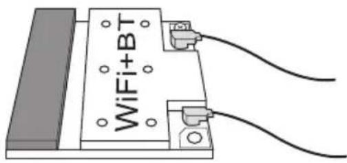
1.4 WiFi + BT Module and ASRock Wi-SD Box
WiFi + BT Module
This motherboard comes with an exclusive WiFi 802.11 a/b/g/n/ac + BT v4.0 module that offers support for WiFi 802.11 a/b/g/n/ac connectivity standards and Bluetooth v4.0. WiFi + BT module is an easy-to-use wireless local area network (WLAN) adapter to support WiFi + BT. Bluetooth v4.0 standard features Smart Ready technology that adds a whole new class of functionality into the mobile devices. BT 4.0 also includes Low Energy Technology and ensures extraordinary low power consumption for PCs. The 2T2R WiFi solution sets a WiFi high speed standard and offers max link rate up to 867Mbps.
* The transmission speed may vary according to the environment.
* The WiFi + BT module is supported under Windows ^® 8 / 8 64-bit / 7 / 7 64-bit only.
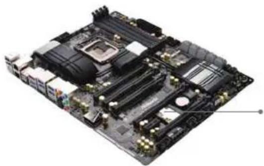
natural_image
Top-down view of a computer motherboard showing CPU socket, RAM slots, and heatsink (no text or labels visible)WiFi + BT Module
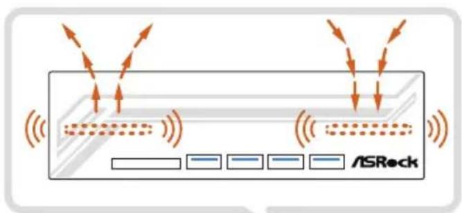
ASRock Wi-SD Box
Thanks to the excellent placement of antennas, ASRock Wi-SD Box comes with two invisible antennas (placed in a vertical/horizontal position), hidden inside the front panel that provides the most stable and unrestricted-direction wireless network coverage, optimized for maximum broadband network. Additionally, it provides four Front USB 3.0 ports for easier USB 3.0 device access, 1 SD Card slot and 1 rack for SSD placement.
ASRock Wi-SD Box
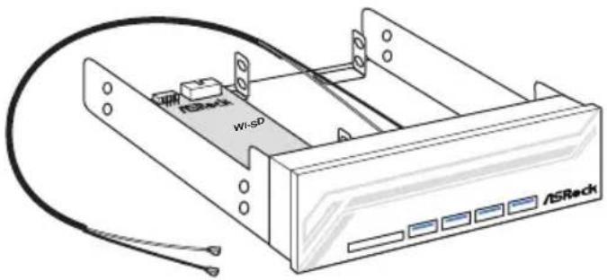
Installing the ASRock Wi-SD Box
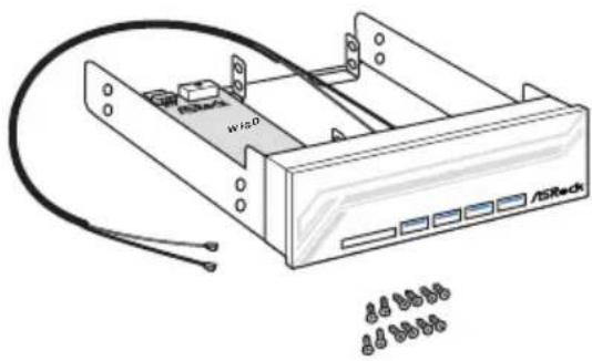
Step 1
Prepare the bundled ASRock Wi-SD Box and screws.

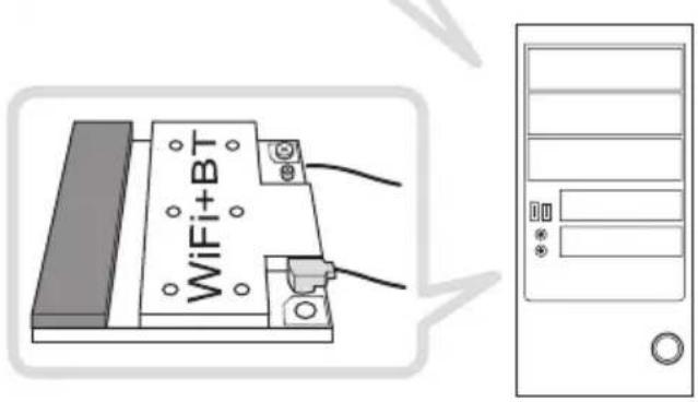
Step 2
Plug the Front USB 3.0 cable into the USB 3.0 header on the Wi-SD Box.
natural_image
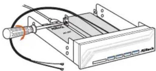
Illustration of an electronic device with labeled ports and cables (no readable text or symbols)Step 3
If you have 2.5" HDD/SSDs, you may insert up to two and secure them in ASRock Wi-SD Box with screws.
natural_image
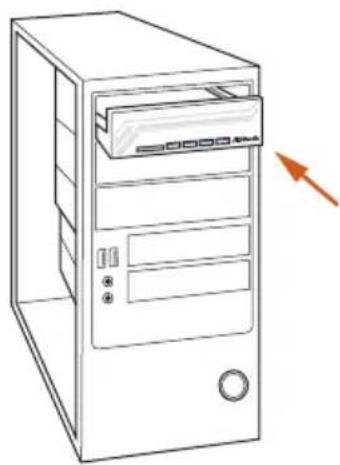
Line drawing of a desktop computer tower with an open door and ventilation slots (no text or symbols)Step4
Install ASRock Wi-SD Box into the drive bay of the chassis.
natural_image
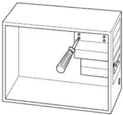
Line drawing of a rectangular enclosure with a screwdriver inserted into the internal compartment (no text or symbols)Step 5
Screw ASRock Wi-SD Box to the drive bay with screws.
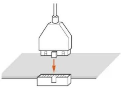
Step 6
Attach the cords to the WiFi + BT module on your motherboard.
natural_image
Diagram of a mechanical device with a downward arrow indicating compression or disassembly (no text or symbols present)Step 8
Plug the Front USB 3.0 cable into the USB 3.0 header on the motherboard.
Chapter 2 Installation
This is an ATX form factor motherboard. Before you install the motherboard, study the configuration of your chassis to ensure that the motherboard fits into it.
Pre-installation Precautions
Take note of the following precautions before you install motherboard components or change any motherboard settings.
Make sure to unplug the power cord before installing or removing the motherboard.
Failure to do so may cause physical injuries to you and damages to motherboard components.
In order to avoid damage from static electricity to the motherboard's components,
NEVER place your motherboard directly on a carpet. Also remember to use a grounded wrist strap or touch a safety grounded object before you handle the components.
Hold components by the edges and do not touch the ICs.
Whenever you uninstall any components, place them on a grounded anti-static pad or in the bag that comes with the components.
When placing screws to secure the motherboard to the chassis, please do not over-tighten the screws! Doing so may damage the motherboard.
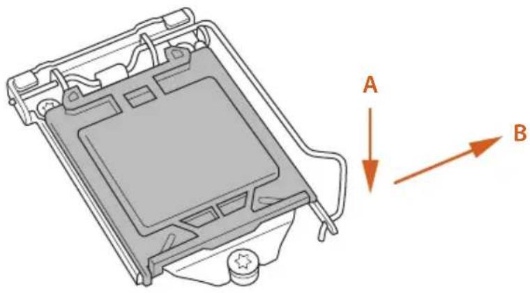
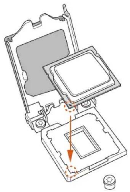
2.1 Installing the CPU

- Before you insert the 1150-Pin CPU into the socket, please check if the PnP cap is on the socket, if the CPU surface is unclean, or if there are any bent pins in the socket. Do not force to insert the CPU into the socket if above situation is found. Otherwise, the CPU will be seriously damaged.
- Unplug all power cables before installing the CPU.
1
natural_image
Technical diagram of a device casing with labeled directional arrows (A and B), no readable text or symbols present.2
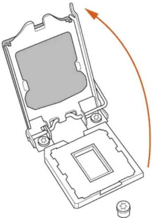
natural_image
Technical line drawing of a mechanical device with internal components and an orange curved arrow indicating rotation (no text or symbols)3
natural_image
Technical diagram of a computer processor internal structure showing mounting holes and internal components (no text or labels)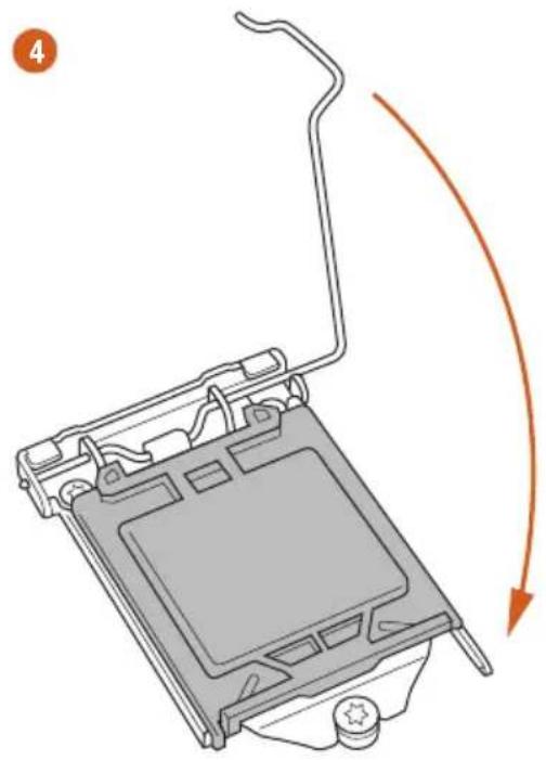
natural_image
Diagram of a computer monitor with an orange curved arrow indicating motion or rotation (no text or symbols present)5
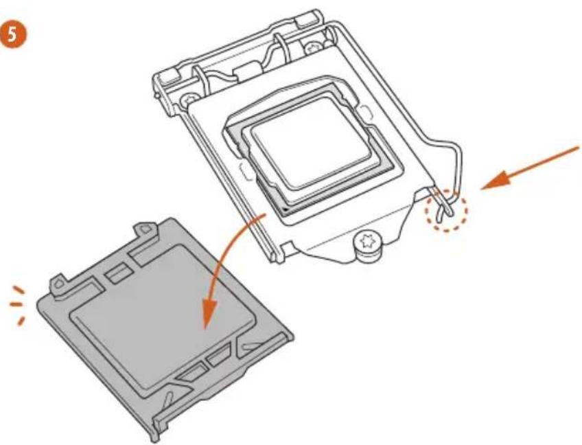
natural_image
Diagram showing a computer processor's internal structure and external casing, with no visible text or symbols.
Please save and replace the cover if the processor is removed. The cover must be placed if you wish to return the motherboard for after service.
2.2 Installing the CPU Fan and Heatsink
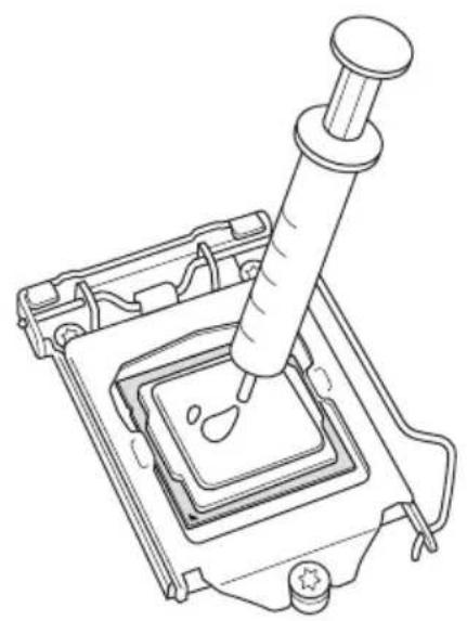
natural_image
Line drawing of a mechanical device with a pipette inserted into a square component (no text or symbols)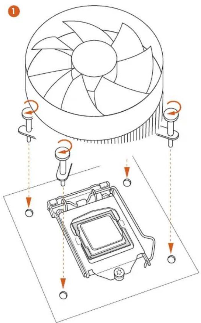

2.3 Installing Memory Modules (DIMM)
This motherboard provides four 240-pin DDR3 (Double Data Rate 3) DIMM slots, and supports Dual Channel Memory Technology.

- For dual channel configuration, you always need to install identical (the same brand, speed, size and chip-type) DDR3 DIMM pairs.
- It is unable to activate Dual Channel Memory Technology with only one or three memory module installed.
- It is not allowed to install a DDR or DDR2 memory module into a DDR3 slot; otherwise, this motherboard and DIMM may be damaged.
Dual Channel Memory Configuration
Priority DDR3_A1 DDR3_A2 DDR3_B1 DDR3_B2
| 1 Populated Populated | |||
| 2 Populated Populated | |||
| 3 Populated Populated Populated Populated |

The DIMM only fits in one correct orientation. It will cause permanent damage to the motherboard and the DIMM if you force the DIMM into the slot at incorrect orientation.
1
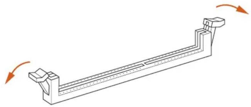
natural_image
Technical line drawing of a mechanical support structure with rotational arrows indicating motion (no text or symbols)2
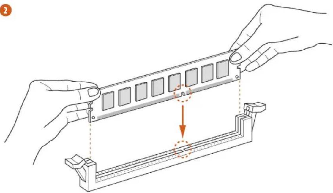
natural_image
Illustration of hands assembling a mechanical component with a highlighted section (no text or symbols)3

natural_image
Isometric line drawing of a rectangular structure with multiple square panels and directional arrows indicating rotation (no text or symbols)2.4 Expansion Slots (PCI and PCI Express Slots)
There are 6 PCI Express slots and 1 mini-PCI Express slot on the motherboard.

Before installing an expansion card, please make sure that the power supply is switched off or the power cord is unplugged. Please read the documentation of the expansion card and make necessary hardware settings for the card before you start the installation.
PCIe slots:
PCIE1 (PCIe 3.0 x16 slot) is used for PCI Express x16 lane width graphics cards. PCIE2 (PCIe 3.0 x16 slot) is used for PCI Express x16 lane width graphics cards. PCIE3 (PCIe 3.0 x16 slot) is used for PCI Express x8 lane width graphics cards. PCIE4 (PCIe 3.0 x16 slot) is used for PCI Express x8 lane width graphics cards. PCIE5 (PCIe 2.0 x1 slot) is used for PCI Express x1 lane width cards. PCIE6 (PCIe 3.0 x16 slot) is used for PCI Express x8 lane width graphics cards.
mini-PCIe slots:
MINI_PCIE1 (mini-PCIe slot) is used for WiFi + BT module.
PCIe Slot Configurations
Single Graphics Card N/A x16 N/AN/AN/A
Two Graphics Cards in
CrossFireX ^TM or SLI ^TM
x16 N/A N/A x16 N/A
Mode
Three Graphics Cards in
3-Way CrossFireX™ Mode
x16 N/A x8 x8 N/A
or 3-Way SLI ^TM Mode
Four Graphics Cards in
4-Way CrossFireX ^TM Mode
x8 N/A x8 x8 x8
or 4-Way SLI ^TM Mode

For a better thermal environment, please connect a chassis fan to the motherboard's chassis fan connector (CHA_FAN1, CHA_FAN2 or CHA_FAN3) when using multiple graphics cards.
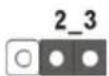
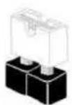
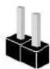
2.5 Jumpers Setup
The illustration shows how jumpers are setup. When the jumper cap is placed on the pins, the jumper is "Short". If no jumper cap is placed on the pins, the jumper is "Open". The illustration shows a 3-pin jumper whose pin1 and pin2 are "Short" when a jumper cap is placed on these 2 pins.
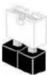
Short
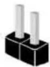
Open
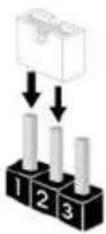
Clear CMOS Jumper (CLRCMOS1)
(see p.1, No. 24)
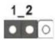
Clear CMOSDefault
CLRCMOS1 allows you to clear the data in CMOS. To clear and reset the system parameters to default setup, please turn off the computer and unplug the power cord from the power supply. After waiting for 15 seconds, use a jumper cap to short pin2 and pin3 on CLRCMOS1 for 5 seconds. However, please do not clear the CMOS right after you update the BIOS. If you need to clear the CMOS when you just finish updating the BIOS, you must boot up the system first, and then shut it down before you do the clear-CMOS action. Please be noted that the password, date, time, and user default profile will be cleared only if the CMOS battery is removed.

The Clear CMOS Button has the same function as the Clear CMOS jumper.
2.6 Onboard Headers and Connectors

Onboard headers and connectors are NOT jumpers. Do NOT place jumper caps over these headers and connectors. Placing jumper caps over the headers and connectors will cause permanent damage to the motherboard.
System Panel Header (9-pin PANEL1)
(see p.1, No. 22)

Connect the power switch, reset switch and system status indicator on the chassis to this header according to the pin assignments below. Note the positive and negative pins before connecting the cables.

PWRBTN (Power Switch):
Connect to the power switch on the chassis front panel. You may configure the way to turn off your system using the power switch.
RESET (Reset Switch):
Connect to the reset switch on the chassis front panel. Press the reset switch to restart the computer if the computer freezes and fails to perform a normal restart.
PLED (System Power LED):
Connect to the power status indicator on the chassis front panel. The LED is on when the system is operating. The LED keeps blinking when the system is in S1/S3 sleep state. The LED is off when the system is in S4 sleep state or powered off (S5).
HDLED (Hard Drive Activity LED):
Connect to the hard drive activity LED on the chassis front panel. The LED is on when the hard drive is reading or writing data.
The front panel design may differ by chassis. A front panel module mainly consists of power switch, reset switch, power LED, hard drive activity LED, speaker and etc. When connecting your chassis front panel module to this header, make sure the wire assignments and the pin assignments are matched correctly.
| Power LED Header(3-pin PLED1)(see p.1, No. 23) | 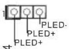 | Please connect the chassis power LED to this header to indicate the system's power status. |
| Serial ATA3 Connectors(SATA3_0_1:see p.1, No. 14)(SATA3_2_3:see p.1, No. 15)(SATA3_4_5:see p.1, No. 16)(SATA3_A1_A2:see p.1, No. 12)(SATA3_A3_A4:see p.1, No. 13) | [SATA3_0_1SATA3_4_5 SATA3_A3_A1_A2SATA3_A3_A3_A1_A2SATA3_A3_A3_A3_A3_A3_A3_A3_A3_A3_A3_A3_A3_A3_A3_A3_A3_A3_A3_A3_A3_A3_A3_A3_A3_A3_A3_A3_A3_A3_A3_A3_A3_A3_A3_A3_A3_A3_A3_A3_A3_A3_A3_A3_A3_A3_A3_A3_A3_A3_A3_BW3 | These ten SATA3 connectors support SATA data cables for internal storage devices with up to 6.0 Gb/s data transfer rate. If the eSATA port on the rear I/O has been connected, the internal SATA3_A4 will not function.To minimize the boot time, use Intel® Z87 SATA ports (SATA3_0) for your bootable devices. |
| [SATA3_0_1SATA3_4_5 SATA3_4_5 SATA3_4_5 SATA3_4_5 SATA3_4_5 SATA3_4_5 SATA3_4_5 SATA3_4_5 SATA3_4_5 SATA3_4_5 SATA3_4_5 SATA3_4_5 SATA3_4_5 SATA3_4_5 SATA3_4_5 SATA3_A4 |  | |
| [SATA3_0_1SATA3_4_5 SATA3_4_5 SATA3_4_5 SATA3_4_5 SATA3_4_5 SATA3_4_5 SATA3_4_5 SATA3_4_5 SATA3_4_5 SATA3_4_5 SATA3_4_5 SATA3_4_5 SATA3_ | ||
| [SATA3_0_1SATA3_4_5 SATA3_4_5 SATA3_4_5 SATA3_4_5 SATA3_4_5 SATA3_4_5 SATA3_4_5 SATA3_4_5 SATA3_4_5 SATA3_4_5 SATA3_4_5 SATA3_4_5 SATA3_ | ||
| [SATA3_0_1SATA3_4_5 SATA3_4_5 SATA3_4_5 SATA3_4_5 SATA3_4_5 SATA3_4_5 SATA3_4_5 SATA3_4_5 SATA3_4_5 SATA3_4_5 SATA3_4_5 SATA3_4_5 SATA3_ |  | |
| [SATA3_0_1SATA3_4_5 SATA3_4_5 SATA3_4_5 SATA3_4_5 SATA3_4_5 SATA3_4_5 SATA3_4_5 SATA3_4_5 SATA3_4_5 SATA3_4_5 SATA3_4_5 SATA3_4_5 SATA3 | ||
| [SATA3_0_1SATA3_4_5 SATA3_4_5 SATA3_4_5 SATA3_4_5 SATA3_4_5 SATA3_4_5 SATA3_4_5 SATA3_4_5 SATA3_4_5 SATA3_4_5 SATA3_4_5 SATA3_4_5 SATA3_5HC7 | To minimize the boot time, use Intel® Z87 SATA ports (SATA3_0) for your bootable devices. | |
| [SATA3_0_1SATA3_4_5 SATA3_4_5 SATA3_4_5 SATA3_4_5 SATA3_4_5 SATA3_4_5 SATA3_4_5 SATA3_4_5 SATA3_4_ |  | |
| USB 2.0 Headers(9-pin USB2_3)(see p.1, No. 28)(9-pin USB4_5)(see p.1, No. 27)(9-pin USB6_7)(see p.1, No. 26)(USB8)(see p.1, No. 25) | 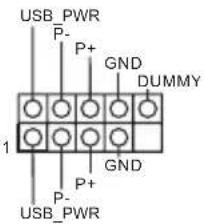 | Besides two USB 2.0 ports on the I/O panel, there are three headers and one port on this motherboard. Each USB 2.0 header can support two ports. |
| [SATA3_0_1SATA3_4_5 SATA3_4_5 SATA3_4_5 SATA3_4_5 SATA3_4_5 SATA3_4_5 SATA3_4_5 SATA3_4_5 SATA3_4_5 SATA3_4_5 SATA3_4_5 SATA3_4_5 SATA3 |
USB 3.0 Headers
(19-pin USB3_6_7)
(see p.1, No. 10)
(19-pin USB3_8_9)
(see p.1, No. 11)
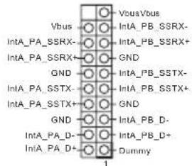
Besides six USB 3.0 ports on the I/O panel, there are two headers on this motherboard. Each USB 3.0 header can support two ports.
Front Panel Audio Header
(9-pin HD_AUDIO1)
(see p.1, No. 32)
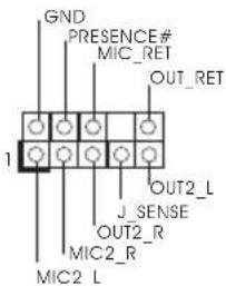
This header is for connecting audio devices to the front audio panel.

- High Definition Audio supports Jack Sensing, but the panel wire on the chassis must support HDA to function correctly. Please follow the instructions in our manual and chassis manual to install your system.
- If you use an AC'97 audio panel, please install it to the front panel audio header by the steps below:
A. Connect Mic_IN (MIC) to MIC2_L.
B. Connect Audio_R (RIN) to OUT2_R and Audio_L (LIN) to OUT2_L.
C. Connect Ground (GND) to Ground (GND).
D. MIC_RET and OUT_RET are for the HD audio panel only. You don't need to connect them for the AC'97 audio panel.
E. To activate the front mic, go to the "FrontMic" Tab in the Realtek Control panel and adjust "Recording Volume".
Chassis Speaker Header
(4-pin SPEAKER1)
(see p.1, No. 21)
DUMMY SPEAKER
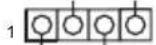
+5V
DUMMY
Please connect the chassis speaker to this header.
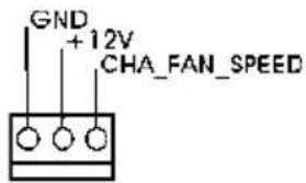
Chassis and Power Fan Connectors (4-pin CHA_FAN1) (see p.1, No. 18)
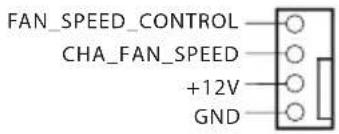
Please connect fan cables to the fan connectors and match the black wire to the ground pin.
(3-pin CHA_FAN2) (see p.1, No. 33) (3-pin CHA_FAN3) (see p.1, No. 1)
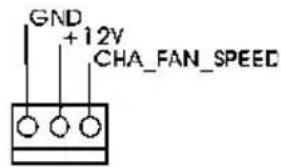
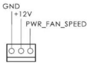
(3-pin PWR_FAN1) (see p.1, No. 6)
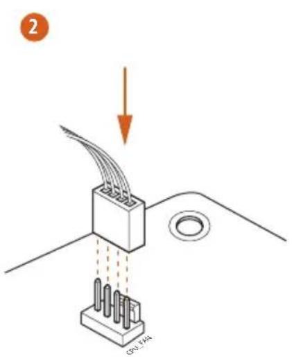
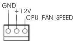
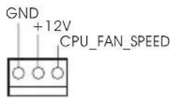
CPU Fan Connectors (4-pin CPU_FAN1) (see p.1, No. 4)
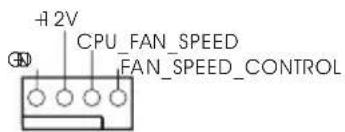
This motherboard provides a 4-Pin CPU fan (Quiet Fan) connector. If you plan to connect a 3-Pin CPU fan, please connect it to Pin 1-3.
(3-pin CPU_FAN2) (see p.1, No. 5)
ATX Power Connector (24-pin ATXPWR1) (see p.1, No. 9)
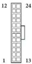
This motherboard provides a 24-pin ATX power connector. To use a 20-pin ATX power supply, please plug it along Pin 1 and Pin 13.
ATX 12V Power Connector (8-pin ATX12V1) (see p.1, No. 2) (8-pin ATX12V2) (see p.1, No. 3)
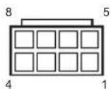
This motherboard provides two 8-pin ATX 12V power connectors. To use a 4-pin ATX power supply, please plug it along Pin 1 and Pin 5.
SLI/XFIRE Power
Connector
(4-pin SLI/XFIRE_ PWR1)
(see p.1, No. 30)
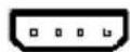
Please connect this connector with a hard disk power connector when two graphics cards are installed on this motherboard.
Infrared Module Header
(5-pin IR1)
(see p.1, No. 29)
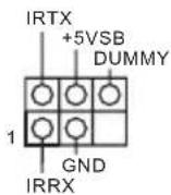
This header supports an optional wireless transmitting and receiving infrared module.
Serial Port Header
(9-pin COM1)
(see p.1, No. 31)
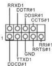
This COM1 header supports a serial port module.
2.7 Smart Switches
The motherboard has three smart switches: Power Switch, Reset Switch and Clear CMOS Button, allowing users to quickly turn on/off the system, reset the system or clear the CMOS values.
Power Switch
(PWRBTN)
(see p.1, No. 19)

Power Switch allows users to quickly turn on/off the system.
Reset Switch
(RSTBTN)
(see p.1, No. 20)

Reset Switch allows
users to quickly reset the system.
BIOS Selection Switch
(BIOS_SEL1)
(see p.1 No. 17)

BIOS Selection Switch allows the system to boot from either BIOS A or BIOS B.

This motherboard has two BIOS chips, a primary BIOS (BIOS_A) and a backup BIOS (BIOS_B), which enhances the safety and stability of your system. Normally, the system will work on the primary BIOS. However, if the primary BIOS is corrupted or damaged, just flip the BIOS Selection Switch to "B", then the backup BIOS will take over on the next system boot. After that, use "Secure Backup UEFI" in the UEFI Setup Utility to duplicate a working copy of the BIOS files to the primary BIOS to ensure normal system operation. For safety issues, users are not able to update the backup BIOS manually. Users may refer to the BIOS LEDs (BIOS_A_LED or BIOS_B_LED) to identify which BIOS is currently activated.
1 Einleitung
ASRock Z87 Extreme9/ac-Support-CD
10 x Serial-ATA- (SATA) Datenkabel (optional)
FCC, CE, WHQL ErP/EuP Ready (alimentation ErP/EuP ready requise)
1 x scheda ASRock SLI_Bridge_3S
1 x scheda ASRock a 3 vie SLI Bridge
1 x ASRock Wi-SD Box
12 viti (per Wi-SD Box)
1 x cavo USB 3.0
1.2 Specifiche
12 Power Phase Design
Dual-Stack MOSFET (DSM)
Supporta la tecnologia Intel Turbo Boost 2.0
Supporta Intel ^® K-Series unlocked CPU Supporta
l'overclocking ASRock BCLK completo
Chipset Intel ^* Z87
2133(OC)/1866(OC)/1600/1333/1066 non-ECC, un-buffered
Supporta Intel ^® Extreme Memory Profile (XMP)1.3/1.2
| Home CloudPurity SoundTM802.11ac WiFi |
4n
(3-pin CHA_FAN2) (bkz sf.1, No. 33) (3-pin CHA_FAN3) (bkz sf.1, No. 1)
(3-pin PWR_FAN1) (bkz sf.1, No. 6)

(3-pin CPU_FAN2) (bkz sf.1, No. 5)
natural_image
Simple graphic with a magnifying glass icon and a horizontal line, no text or symbols present.1.1 パッケージの内容
1.2 仕様
| TM | |
| CPU | TM |
| " Z87" | |
| TM | TM | ||
| CrossFireXTM | TM | ||
| TM | TM | TM | |
| SLITM | |||
(4096x2304) @ 24Hz
LAN
日本語
LAN
I/O
CD
Splashtop Streamer
os


1.3 ジャンパー設定
Short
Open

(CLRCMOS1)
1_2

2_3


Extreme Memory Profile (XMP)1.3/1.2
扩充槽
PCIE6:单 - x16 (PCIE2);双 - x16 (PCIE1) / x16 (PCIE4);三 - x8 (PCIE1) / x8 (PCIE3) / x16 (PCIE4);四 - x8 (PCIE1) / x8 (PCIE3) / x8 (PCIE4) / x8 (PCIE6))
*PCIE2 槽被占用时,PCIE1、PCIE3、PCIE4 和 PCIE6 槽将被禁用。
(Voltage Multi-adjustment)
支持光盘
MediaEspresso 6.5 试用版、Google Chrome 浏览器和工具栏、Start8、MeshCentral、Splashtop Streamer
硬件
扇速度)
操作系统
认证
K-Series unlocked CPU,支援
晶片組
Z87
記憶體
Extreme Memory Profile (XMP)1.3/1.2
擴充插槽
RESET (Switch Atur Ulang):
Tombol Atur Ulang (RSTBTN)
If you need to contact ASRock or want to know more about ASRock, you're welcome to visit ASRock's website at http://www.asrock.com; or you may contact your dealer for further information. For technical questions, please submit a support request form at http://www.asrock.com/support/tsd.asp
ASRock Incorporation
2F., No.37, Sec. 2, Jhongyang S. Rd., Beitou District,
Taipei City 112, Taiwan (R.O.C.)
ASRock EUROPE B.V.
Bijsterhuizen 3151
6604 LV Wijchen
The Netherlands
Phone: +31-24-345-44-33
Fax: +31-24-345-44-38
ASRock America, Inc.
13848 Magnolia Ave, Chino, CA91710
U.S.A.
Phone: +1-909-590-8308
Fax: +1-909-590-1026