441 - Water pump Liberty Pumps - Free user manual and instructions
Find the device manual for free 441 Liberty Pumps in PDF.
| Product Type | Battery Backup Sump Pump |
| Brand | Liberty Pumps |
| Model | 441 |
| Use | Backup sump pump for power outages |
| Power Supply | 12 VDC battery (deep cycle) |
| Charger | Input voltage 110-120 VAC, output 12 VDC 1 A |
| Max Discharge Head | 5.5 m (18 ft) |
| Max Flow (at 2.4 m) | 1500 GPH (5678 L/h) |
| Recommended Battery | 12 V deep cycle, size 27 or 31 (StormCell) |
| Runtime (with charged battery) | Up to 4.25 h continuous or 6 days cycling (4 times/h, 10 gal at 10 ft) |
| Switch Type | Vertical Float |
| Alarm | Audible and visual, with 24 h silence feature |
| Max Liquid Temperature | 40 °C (104 °F) |
| Operating Temperature (charger) | 0 to 45 °C |
| Charger Weight | 0.4 kg (0.9 lb) |
| Charger Dimensions (L × W × H) | 105 × 68 × 35 mm |
| Standards | UL / cUL, FCC, BC, DOE |
| Package Includes | Pump, check valve, tee, charger, terminal plate, 20 A fuse, wires, clamp, strap, tape, screws |
| Maintenance | Quarterly check: operation test, debris cleaning |
| Safety | Disconnect power before maintenance; use PPE; grounding required |
| Warranty | 3 years (excluding battery) |
Frequently Asked Questions - 441 Liberty Pumps
User questions about 441 Liberty Pumps
0 question about this device. Answer the ones you know or ask your own.
Ask a new question about this device
Download the instructions for your Water pump in PDF format for free! Find your manual 441 - Liberty Pumps and take your electronic device back in hand. On this page are published all the documents necessary for the use of your device. 441 by Liberty Pumps.
USER MANUAL 441 Liberty Pumps
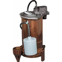
Model 441 Battery Back-up System
Features
-
Advanced charging system automatically recharges battery after use
• Audible alarm and light advises of emergency pump operation
• Works with marine-type deep cycle batteries -
StormCell® battery recommended
- Battery not included
natural_image
Product photo of a Liberty Pumps 12 Volt 1 AMP system with attached pump and charging unit (no visible text or symbols on main components)Contents
Safety Precautions 3
General Information 5
System Operation 5
Assembly Methods 6
Back-up Pump Preparation 7
Back-up Pump Assembly 8
Battery & Charger Connections 11
Charger Operation 13
Maintenance 14
Troubleshooting 15
Warranty 16
Safety Guidelines
| This safety alert symbol is used in the manual and on the pump to alert of potential risk for serious injury or death. | |
| This safety alert symbol identifiesrisk of electric shock. It is accompanied with an instruction intended to minimize potential risk of electric shock. | |
| This safety alert symbol identifiesrisk of fire. It is accompanied with an instruction intended to minimize potential risk of fire. | |
| This safety alert symbol identifiesrisk of serious injury or death. It is accompanied with an instruction intended to minimize potential risk of injury or death. | |
| This safety alert symbol identifiesbattery hazards. It is accompanied with an instruction intended to minimize potential risk from the battery. | |
| △DANGER | Warns of hazards that, if not avoided,willresult in serious injury or death. |
| △WARNING | Warns of hazards that, if not avoided,couldresult in serious injury or death. |
| △CAUTION | Warns of hazards that, if not avoided,couldresult in minor or moderate injury. |
| NOTICE | Signals an important instruction related to the pump. Failure to follow these instructions could result in pump failure or property damage. |
| ⚠WARNING | Read every supplied manual before using pump system. Follow all the safety instructions in manual(s) and on the pump. Failure to do so could result in serious injury or death. | |
| NOTICE | Installer: manual must remain with owner or system operator/maintainer. | |
| Record information from pump nameplate: | ||
| Keep this manual handy for future reference. | Pump Model #: | |
| For replacement manual, visit LibertyPumps.com, or contact Liberty Pumps at 1-800-543-2550. | Pump Serial #: | |
| Manufacture Date: | ||
| Retain dated sales receipt for warranty. | Install Date: | |
WARNING

RISK OF ELECTRIC SHOCK
■ Accidental contact with electrically live parts, items, fluid, or water can cause serious injury or death.
■ Always disconnect pump(s) from power source(s) before handling or making any adjustments to either the pump(s), the pump system, or the control panel.
■ All installation and maintenance of pumps, controls, protection devices, and general wiring shall be done by qualified personnel.
The pump shall be plugged into a properly fused electrical outlet with a ground fault circuit interrupter (GFCI) that conforms to current National Electric Code (NEC) and all applicable local codes. All wiring must be performed by qualified personnel.
All electrical and safety practices shall be in accordance with the National Electrical Code ^® , the Occupational Safety and Health Administration, or applicable local codes and ordinances.
Pump shall be properly grounded using its supplied grounding conductor. Do not bypass grounding wires or remove ground prong from attachment plugs. Failure to properly ground the pump system can cause all metal portions of the pump and its surroundings to become energized.
■ Do not handle or unplug the pump with wet hands, when standing on damp surface, or in water unless wearing Personal Protective Equipment.
■ Always wear dielectric rubber boots and other applicable Personal Protective Equipment (PPE) when water is on the floor and an energized pump system must be serviced, as submerged electrical connections can energize the water. Do not enter the water if the water level is higher than the PPE protection or if the PPE is not watertight.
- Do not lift or carry a pump or a float assembly by its power cord. This will damage the power cord, and could expose the electrically live wires inside the power cord.
■ The electrical power supply shall be located within the length limitations of the pump power cord, and for below grade installations, it shall be at least 4 ft (1.22 m) above floor level.
■ Do not use this product in applications where human contact with the pumped fluid is common (such as swimming pools, fountains, marine areas, etc.).
■ Protect the power and control cords from the environment. Unprotected power and control (switch) cords can allow water to wick through ends into pump or switch housings, causing surroundings to become energized.
■ Do not use metal or any other electrical conducting material to raise the float or contact anything inside an electrically live sump pit.
WARNING

RISK OF FIRE
- Use PVC cement in a well-ventilated area away from fire or flames. Follow the PVC cement and primer manufacturer's instructions.
■ Do not use an extension cord to power the product. Extension cords can overload both the product and extension cord supply wires. Overloaded wires will get very hot and can catch on fire.
This product requires a separate, properly fused and grounded branch circuit, sized for the voltage and amperage requirements of the pump, as noted on the nameplate. Overloaded branch circuit wires will get very hot and can catch on fire.
■ Do not use to pump flammable or explosive fluids such as gasoline, fuel oil, kerosene, etc. Do not use in flammable and/or explosive atmosphere. Sparks could ignite flammable liquids.
WARNING

RISK OF SERIOUS INJURY OR DEATH
■ Do not modify the pump/pump system in any way. Modifications may affect seals, change the electrical loading of the pump, or damage the pump and its components.
■ All pump/pump system installations shall be in compliance with all applicable Federal, State, and Local codes and ordinances.
■ Do not allow children to play with the pump system.
■ Do not allow any person who is unqualified, to have contact with this pump system. Any person who is unaware of the dangers of this pump system, or has not read this manual, can easily be injured by the pump system.
■ Wear adequate Personal Protective Equipment when working on pumps or piping that have been exposed to wastewater. Sump and sewage pumps often handle materials that can transmit illness or disease upon contact with skin and other tissues.
■ Do not remove any tags or labels from the pump or its cord.
- Keep clear of suction and discharge openings. To prevent injury, never insert fingers into pump while it is connected to a power source.
■ Do not use this product with flammable, explosive, or corrosive fluids. Do not use in a flammable and/or explosive atmosphere as serious injury or death could result.
This product contains chemicals known to the State of California to cause cancer and birth defects or other reproductive harm. www.p65warnings.ca.gov.
WARNING

BATTERY HAZARDS
Battery voltage can cause serious or fatal electrical shock. Follow the battery manufacturer's recommendations for maintenance and safe use of battery before using charger.
■ Explosive gases develop during normal battery operation. Keep sparks and flame (pilot light) away from battery. Never smoke in vicinity of battery.
■ Battery acid is corrosive. Wear adequate Personal Protective Equipment when working with the battery.
■ Never allow the battery DC terminals to touch each other. This can cause severe burns and start a fire. For added safety, protect the battery in provided battery box.
NOTICE
◆ Pump clear water only with this pump.
Do not dispose of materials such as paint thinner or other chemicals down drains. Doing so could chemically attack and damage pump system components and cause product malfunction or failure.
Do not use pumps with fluid over 104°F (40°C). Operating the pump in fluid above this temperature can overheat the pump, resulting in pump failure.
Do not use pump system with mud, sand, cement, hydrocarbons, grease, or chemicals. Pump and system components can be damaged from these items causing product malfunction or failure. Additionally, flooding can occur if these items jam the impeller or piping.
Do not run dry.
- Do not expose pump or discharge to freezing temperatures.
◆ Maximum vertical pumping distance is 18 feet (5.5 m).
If a Carbon Monoxide (CO) sensor is installed, it must be at least 15 feet away from the battery charger in order to avoid nuisance CO alarms. Refer to the CO detector's installation guidelines for more information.
◆ Locate charger as far away from battery as DC cables permit. - Never place charger directly above battery being charged as gases from battery will corrode and damage charger.
- Never allow battery acid to drip on charger when reading gravity or filling battery.
- Do not operate charger in a closed-in area or restrict ventilation in any way.
Do not operate charger if it has received a sharp blow, been dropped, or otherwise damaged in any way; take it to a qualified service professional.
Use charger only for charging a 12 V Lead Acid Battery. It is not intended to supply power to a low voltage electrical system as the battery may burst and cause injury and property damage.
◆ Never charge a frozen battery.
◆ A size 27 battery will provide the same performance as a size 31 battery, but for a shorter length of time.
To protect battery box from chipping and gouging, do not let the battery box sit on a concrete floor. Install the battery box on a shelf or a protective pad (plywood, 2x4s, etc.).
◆ Always install the battery box in a dry location that is protected from flooding.
The Model 441 battery back-up sump pump system is not a substitute for a primary sump pump. It is designed to
temporarily provide backup to a primary sump pump during a power outage or other problem that prevents normal operation of the primary pump.
Install this system during a time when the primary pump will not be needed. If this is not possible and water will enter the sump pit during the installation process, an additional pump may be required to keep the pit dry.
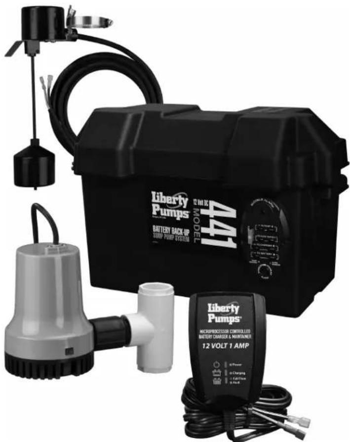
Included Parts
-
12 V Battery Back-up Sump Pump
-
Check Valve
-
Reducer Tee with Pipe Nipple and (2) Reducer Bushings
-
Back-up Switch
- Hose Clamp
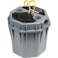
- Battery Box
- Battery Box Strap
- Charger Kit
- Terminal Block
- Battery Charger & Maintainer
-Battery Leads (Black & Red)
- Fuse
- Double-Sided Tape
– (2) Screws (for optional mounting)
- Installation Manual
text_image
Technical diagram of a battery backup system with labeled components and a version of the installed model.Syst em Oper a tion
The Model 441 back-up pump will activate when the sump water triggers the back-up pump's float switch. The system will continue to operate automatically until the issue with the primary pump is corrected, and for as long as the charge in the battery installed with the system lasts.
Charger
The charger is designed to continuously charge, maintain peak charge, and monitor battery health. With AC power applied, the charger can be left unattended and will not overcharge or damage the battery. It will also monitor and notify the user via an alarm if the battery is no longer suitable for use.
The time the charger takes to recharge a battery depends on the battery's reserve capacity and its current state of discharge. The charger may take as long as 10 days to charge the battery to a maintenance charging point. For more detailed information, refer to Charger Operation on page 13.
Battery
The total time the battery back-up can operate in standby while the AC power is off greatly depends on the battery installed with the system. Liberty Pumps recommends using a Liberty Pumps StormCell size 27 or 31 Deep Cycle Battery with the 441 system. The StormCell batteries have been specifically designed to maximize reserve capacity time (the time the battery can operate continuously before it needs to be recharged). Additionally, StormCell batteries have been modified to provide the highest resistance to battery plate degradation due to repeated charging and continuous maintenance charging. With a charged 27 or 31 deep cycle battery, this back-up system can expect to operate for 4.25 hours continuously or up to 6 days cycling on 4 times an hour, moving 10 gallons of water at 10 feet of vertical lift.
Note: In an emergency when the system's deep cycle battery has been depleted, any 12 V automobile battery, or other lead acid battery, may be used to keep the back-up pump operational. Be sure to replace the deep cycle battery back into the system as soon as possible. Automobile batteries have much lower reserve capacities and require frequent, repeated charging that will result in early battery failure.
Battery Back-up Pump
The Model 441 back-up pump system flow rates are directly tied to the voltage the battery supplies to the pump while it is running. The flow rates shown in Table 1 were generated by supplying the 441 pump with 12.1 V at the battery terminals. When the battery supplies the pump with more than 12.1 V, the pump's flow rate will be greater than in Table 1; likewise, flow rates will be less when the voltage is less than 12.1 V.
Table 1. Back-up Pump Flow Rates
| Vertical Pumping Head (ft) | 8 10 | 12 16 18 | |||
| Gallons Per Hour | 500 1300 | 1050 450 | 0 |
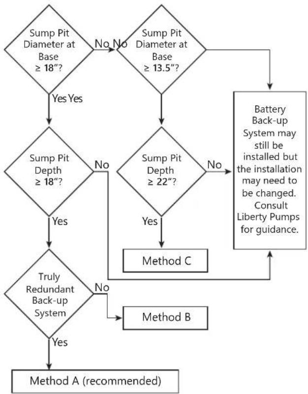
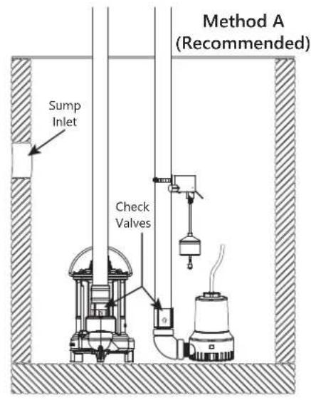
There are three ways to assemble and install the battery back-up pump, depending on sump pit diameter/depth and desire for a truly redundant back-up system. Select appropriate method by referring to Figure 1. Any method is acceptable, but Method A is recommended. Examples are shown in Figure 2 as a visual aid.
Note: Always install the back-up sump pump as close to the bottom of the sump pit as possible.
Note: All assembly methods require the back-up pump switch to have free movement.
flowchart
graph TD
    A["Sump Pit Diameter at Base ≥ 18""] -->|Yes Yes| B["Sump Pit Depth ≥ 18""]
    A -->|No No| C["Sump Pit Diameter at Base ≥ 13.5""]
    B -->|Yes| D["Truly Redundant Backup System"]
    B -->|No| E["Sump Pit Depth ≥ 22""]
    C --> F["Battery Back-up System may still be installed but the installation may need to be changed. Consult Liberty Pumps for guidance."]
    D -->|Yes| G["Method A (recommended)"]
    D -->|No| H["Method B"]
    E --> I["Method C"]
    F --> I
    G --> I
    H --> I
    I --> J["Method A (recommended)"]
Figure 1. Method Decision
text_image
Method A (Recommended) Sump Inlet Check Valves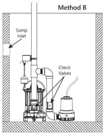
text_image
Method B Sump Inlet Check Valves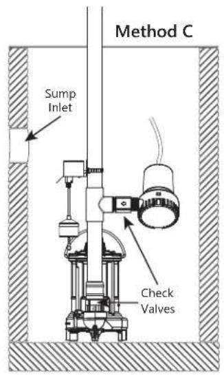
text_image
Method C Sump Inlet Check ValvesFigure 2. Assembly Methods
Basic Tools and Materials Needed
Methods A, B & C
• Primary pump check valve (if not already installed)
• Additional pump to keep well dry (as needed)
- Size 27 or 31 Deep Cycle Battery
(Liberty Pumps StormCell® Battery recommended)
- Channel locks or pliers
- Tape measure
- 5/16" socket wrench or nut driver
• Hacksaw or other pipe cutter
- Pencil/marker
- Thread seal tape
• PVC cement (solvent weld)
- PVC primer
- Cloth towel
Additional Tools and Material for Method A
• Additional PVC pipe for separate discharge line
- Rubber coupling with clamps to fit the discharge pipe diameter (if check valve not installed)
• (1) 1-1/4" 90° elbow
Additional Tools and Material for Method B
• Additional PVC pipe for connecting back-up pump between elbows
- Rubber coupling with clamps to fit the discharge pipe diameter
• (2) 1-1/4" 90° elbows
• (1) 1-1/4" close pipe nipple
Additional Tools and Material for Method C
- Rubber coupling with clamps to fit the discharge pipe diameter
B a ck-up P um p P repa ration
WARNING

RISK OF ELECTRIC SHOCK
- Do not lift or carry a pump or a float assembly by its power cord. This will damage the power cord, and could expose the electrically live wires inside the power cord.
■ Do not use metal or any other electrical conducting material to raise the float or contact anything inside an electrically live sump pit.
CAUTION
Do not turn the pumps ON until all the fittings are connected with PVC cement and the cement has dried. Loose fittings can unexpectedly disconnect from pipes and cause personal injury and flooding.
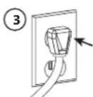
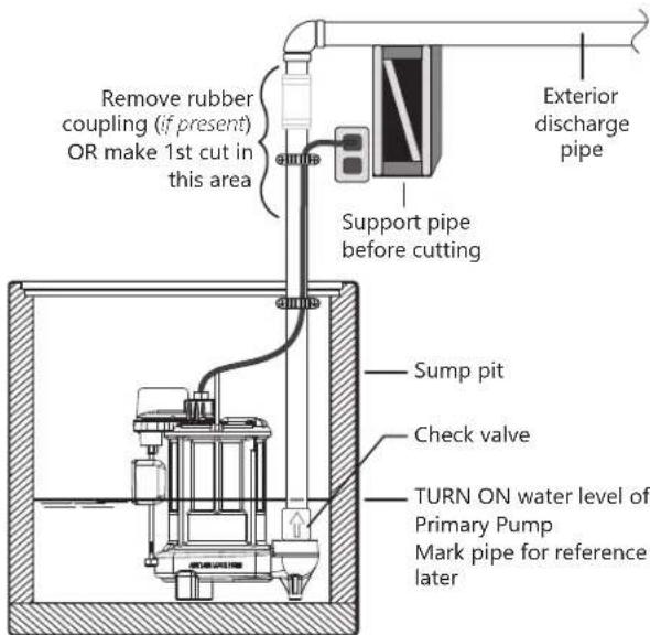
To avoid an injury from a collapse of plumbing, support the pipe above the separation before cutting or disassembly. See Figure 3.
NOTICE
- Be prepared for water to leak from the coupling or piping when disassembling or cutting the discharge pipe. Protect system components, tools, and supplies from getting wet. Dry any work areas that get wet immediately.
For assembly Method A, a primary pump check valve is recommended as an advisable plumbing practice.
For assembly Methods B and C, a primary sump pump check valve is required in the back-up sump pump system. Verify the presence of a check valve in the primary sump pump. If no check valve is in place, one will need to be installed during the assembly process.
- Locate the TURN ON water level of the primary sump pump. Mark this location on the discharge pipe. See Figure 3.
- Drain the sump pit. The water level must be pumped down as low as possible before going on to the next step.
To drain the sump pit:
a. Raise the float on the float switch until the pump turns on. Use a wooden broom handle or stick to do this.
OR
b. If the sump pump has a piggyback-type power cord, remove the float switch/power cord plug from the outlet and plug the pump power cord plug directly into the outlet.
- Confirm sump pit has been drained but do not let the pump run dry as this will damage the pump.
Note: A second pump may be required to keep the well dry during installation of the back-up pump.
-
Unplug the primary pump and any other electrical equipment in the sump (i.e., alarm).
-
Method A: The primary pump will stay in the pit with the discharge pipe intact, unless a check valve is to be installed. Continue to Assembly Method A. If installing a check valve, continue to Step 6.
-
Methods B and C: The primary sump pump will need to be separated from the discharge pipe and removed from pit. To separate the primary pump from the discharge pipe:
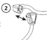
a. For applications with rubber couplings, remove the coupling clamp with a nut driver.
b. For applications without rubber couplings, cut the PVC discharge pipe above the basement floor, at a comfortable level. A new rubber coupling is needed for reassembly. See Figure 3.
Note: The discharge pipe will be filled with water. Drain the water from the discharge pipe assembly. Keep the work area dry.
c. Use handle to lift the primary pump and discharge pipe assembly out of the sump.
- Continue to Back-up Pump Assembly.
text_image
Remove rubber coupling (if present) OR make 1st cut in this area Support pipe before cutting Exterior discharge pipe Sump pit Check valve TURN ON water level of Primary Pump Mark pipe for reference laterFigure 3. Mark and Cut Pipe
B a ck-up P ump A ssembly
WARNING

RISK OF FIRE
■ Use PVC cement in a well-ventilated area away from fire or flames. Follow the PVC cement and primer manufacturer's instructions.
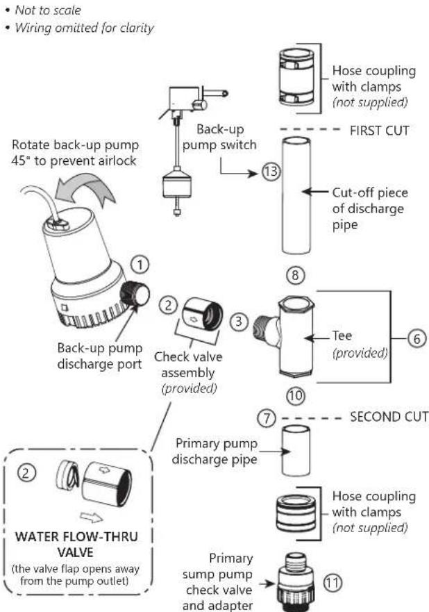
Assembly Method A
Liberty Pumps recommends Method A for the most fail-safe back-up pump system. The back-up pump is plumbed with a separate discharge line. The minimum required sump basin diameter is 18" at the bottom of the pit, and the minimum recommended depth of the sump basin is 18".
IMPORTANT: A primary pump check valve is recommended.
Back-up Pump Installation (Method A)
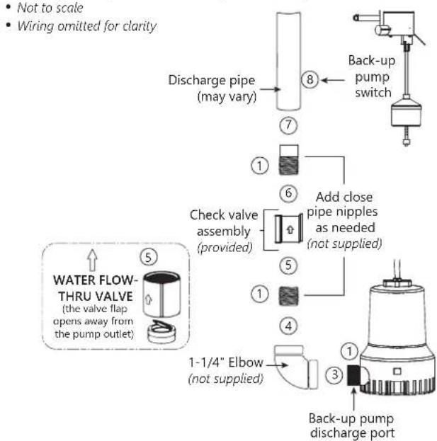
flowchart
graph TD
    A["Water Flow-THRU VALVE (the valve flap opens away from the pump outlet)"] --> B["Check valve assembly (provided)"]
    B --> C["Add close pipe nipples as needed (not supplied)"]
    C --> D["1-1/4" Elbow (not supplied)"]
    D --> E["Back-up pump discharge port"]
    E --> F["Discharge pipe (may vary)"]
    F --> G["Back-up pump switch"]
    G --> H["Not to scale"]
    G --> I["Wiring omitted for clarity"]
Figure 4. Installation Method A
- Apply (2) wraps of thread seal tape to all threads.
- If primary pump does not have a check valve, install one now. Make sure the check valve is installed in the correct direction.
- Thread a 90° elbow onto the discharge of the back-up pump. Take care not to overtighten and strip threads.
- Thread one of the close pipe nipples into the elbow.
- Thread the check valve assembly onto the close pipe nipple. IMPORTANT: Make sure the check valve is installed in the correct direction. See the inset drawing in Figure 4.
- Thread a close pipe nipple into the other end of the check valve.
-
Connect a length of pipe into the top of the check valve in the back-up pump discharge.
-
Mount the pre-assembled vertical pump switch to the new discharge pipe with the provided clamp. Adjustments may be needed later and can be achieved by loosening the clamp and sliding the switch bracket up or down on the discharge pipe to attain the desired activation level.
- Continue to Final Assembly (Method A) on page 11.
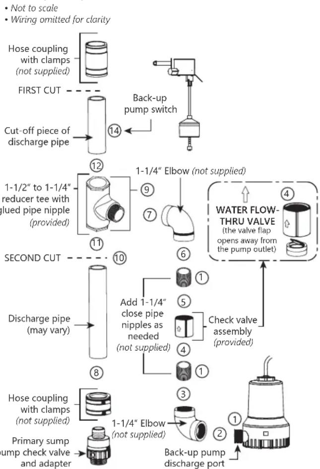
Assembly Method B
For Method B, both pumps are installed on the floor of the sump pit. The minimum required sump basin diameter is 18" at the bottom of the pit, and the minimum recommended depth of the sump basin is 18".
IMPORTANT: There must be a check valve installed in the primary sump pump discharge pipe between the tee and the primary sump pump. This will prevent water from recirculating back into the pit through the primary pump when the back-up sump pump turns on.
Back-up Pump Installation (Method B)
flowchart
graph TD
    A["Primary sump pump check valve and adapter"] --> B["Hose coupling with clamps (not supplied)"]
    B --> C["Add 1-1/4" close pipe nipples as needed (not supplied)"]
    C --> D["Check valve assembly (provided)"]
    D --> E["WATER FLOW-THRU VALVE (the valve flap opens away from the pump outlet)"]
    E --> F["Back-up pump discharge port"]
    F --> G["1-1/4" Elbow (not supplied)"]
    G --> H["1-1/2" to 1-1/4" reducer tee with lued pipe nipple (provided)"]
    H --> I["SECOND CUT"]
    I --> J["1-1/4" Elbow (not supplied)"]
    J --> K["Back-up pump switch"]
    K --> L["1-1/4" Elbow (not supplied)"]
    L --> M["1-1/2" to 1-1/4" reducer tee with lued pipe nipple (provided)"]
    M --> N["SECOND CUT"]
    N --> O["Hose coupling with clamps (not supplied)"]
    O --> P["Add 1-1/4" close pipe nipples as needed (not supplied)"]
    P --> Q["Check valve assembly (provided)"]
    Q --> R["WATER FLOW-THRU VALVE (the valve flap opens away from the pump outlet)"]
    R --> S["Back-up pump discharge port"]
    S --> T["1-1/4" Elbow (not supplied)"]
    T --> U["Add 1-1/4" close pipe nipples as needed (not supplied)"]
    U --> V["Check valve assembly (provided)"]
    V --> W["WATER FLOW-THRU VALVE (the valve flap opens away from the pump outlet)"]
    W --> X["Back-up pump discharge port"]
    X --> Y["1-1/4" Elbow (not supplied)"]
    Y --> Z["Add 1-1/4" close pipe nipples as needed (not supplied)"]
    Z --> AA["Check valve assembly (provided)"]
    AA --> AB["WATER FLOW-THRU VALVE (the valve flap opens away from the pump outlet)"]
    AB --> AC["Back-up pump discharge port"]
Figure 5. Installation Method B
- Apply (2) wraps of thread seal tape to all threads.
- Thread a 90° elbow onto the discharge of the back-up pump. Take care not to overtighten and strip threads.
- Thread one of the close pipe nipples into the elbow.
- Thread the check valve assembly onto the close pipe nipple. IMPORTANT: Make sure the check valve is installed in the correct direction. See the inset drawing in Figure 5.
- Thread a close pipe nipple into the other end of the check valve.
- Thread the second 90° elbow onto the pipe nipple.
- Thread the tee pipe nipple into the elbow and set this assembly aside.
- Install a short length of pipe into the top of the check valve in the primary pump discharge. If there is no check valve on the primary pump, install now.
- If the discharge pipe is 1-1/2", the reducer bushings are not needed and should be removed. If the discharge pipe diameter is 1-1/4", remove the reducer bushings. Position (will be cemented later) them into the tee.
- Using the assembled back-up pump, mark a line on the primary discharge where the tee sits. Measure the socket depth (interior ridge) inside the tee. Add that amount over the line and make a cut.
- Slip the tee and the back-up pump subassembly onto the short pipe exiting the primary pump.
- Position (will be cemented later) the cut-off piece of pipe into the top of the tee (with reducer bushing if 1-1/4" pipe).
- Clean the pipe ends with a cloth towel and set the cut-off piece of discharge pipe aside.
- Mount the pre-assembled vertical pump switch to the discharge pipe above the tee with the provided clamp. Adjustments may be needed later and can be achieved by loosening the clamp and sliding the switch bracket up or down on the discharge pipe to attain the desired activation level.
- Continue to Cut the Discharge Pipe (Methods B & C) on page 11.
Assembly Method C
For Method C, the back-up pump is installed above the primary sump pump. The minimum required sump basin diameter for this type of installation is 13.5" at the bottom of the pit, and the minimum recommended depth of the basin is 22".
IMPORTANT: There must be a check valve installed in the primary sump pump discharge pipe between the tee and the primary sump pump. This will prevent water from recirculating back into the pit through the primary pump when the back-up sump pump turns on.
Back-up Pump Installation (Method C)
flowchart
graph TD
    A["Rotate back-up pump 45° to prevent airlock"] --> B["Back-up pump discharge port"]
    B --> C["Check valve assembly (provided)"]
    C --> D["Check valve with clamps (not supplied)"]
    D --> E["Hose coupling with clamps (not supplied)"]
    E --> F["FIRST CUT"]
    F --> G["Cut-off piece of discharge pipe"]
    G --> H["Tee (provided)"]
    H --> I["SECOND CUT"]
    I --> J["Primary pump discharge pipe"]
    J --> K["Hose coupling with clamps (not supplied)"]
    K --> L["Primary sump pump check valve and adapter"]
    L --> M["WATER FLOW-THRU VALVE (the valve flap opens away from the pump outlet)"]
Figure 6. Installation Method C
-
Apply (2) wraps of thread seal tape to all threads.
-
Thread the check valve onto the back-up pump discharge ensuring that the valve housing and inner valve flap are oriented correctly. Refer to inset in Figure 6.
-
Thread the tee/nipple assembly into the check valve.
-
Tighten the tee into the close nipple. If needed, hold the check valve with the channel locks, insert the screwdriver into the tee for leverage, and tighten the tee with the screwdriver. Finish with the tee in a straight up and down (vertical) position and the pump oriented at a 45^ angle to prevent airlock.
-
Clean the pipe ends with the cloth towel.
-
If the discharge pipe is 1-1/4", prime and cement the reducer bushings into the tee. Position (will be cemented later) the pipe into the bushing.
-
Using the assembled back-up pump, mark a line on the primary discharge where the tee sits. Measure the socket depth (interior ridge) inside the tee. Add that amount over the line and make a cut.
-
Position (will be cemented later) the cut-off piece of discharge pipe into the top of the tee.
-
Clean the pipe ends with a cloth towel and set the cut-off piece of discharge pipe aside.
-
Slip the tee and the back-up pump assembly onto the short pipe exiting the primary pump.
-
If there is no check valve on the primary pump, install now in the primary sump pump discharge pipe between the tee and the pump.
-
Position (will be cemented later) the assembly onto the primary discharge pipe.
-
Mount the back-up pump float switch assembly loosely to the discharge pipe per Figure 7. Do not fully tighten the clamp at this time as adjustments may be needed later.
-
Continue to Cut the Discharge Pipe (Methods B & C).
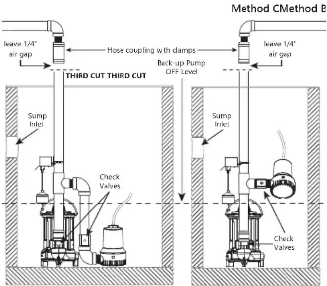
Cut the Discharge Pipe (Methods B & C)
NOTICE
- Be prepared for water to leak from the coupling or piping when disassembling or cutting the discharge pipe. Protect system components, tools, and supplies from getting wet. Dry any work areas that get wet immediately.
- Put the newly assembled dual pump back-up system into the sump pit.
The discharge pipe now overlaps the discharge pipe that leads outside.
- Mark the discharge pipe where it should be cut.
Be sure to leave a 1/4" air gap between the ends of the pipes. This gap will absorb the noise from vibration and allow for flexibility.
- Make the third cut as shown in Figure 7.
Back-up Pump Installation
text_image
Method CMethod B leave 1/4" air gap Hose coupling with clamps back-up Pump OFF Level leave 1/4" air gap THIRD CUT THIRD CUT Sump Inlet Check Valves Sump Inlet Check ValvesFigure 7. Remove Excess Discharge Pipe
Trial Assembly (Methods B & C)
- Connect the pump discharge pipe to the exterior discharge pipe with a rubber coupling and clamps.
Do not tighten the clamps until all the final adjustments are complete.
- Make the final adjustments. Make sure the pumps and the switches do not interfere with each other. Make sure there is plenty of room for the float switches to either swing or to move up and down from their "off" to their "on" positions.
Preliminary Assembly (Methods B & C)
- Mark the pipe and fittings at all connections with a pencil. These marks will be used as a reassembly guide when joining with primer and cement to be sure everything is still in the right place and nothing has moved.
- Loosen the rubber coupling and clamp connection.
- Carefully pull the dual pump back-up system out of the pit.
- Take the tee assembly off the primary discharge pipe. Do not unscrew any of the thread seal taped fittings.
- Prepare all unconnected PVC pipe ends with primer.
- Apply cement to these PVC fittings where indicated by the marks.
Final Assembly (Method A)
- Position the back-up pump into the pit.
- Complete the back-up pump separate discharge line.
- Make the final float switch adjustments, tighten the mounting clamp, and secure wires as needed.
Final Assembly (Methods B & C)
- Position the dual pump back-up system back into the pit.
- Install and tighten the rubber coupling and clamps.
- Make the final float switch adjustments, tighten the mounting clamp, and secure wires as needed.
B a tter y & Charger Connections
Follow the battery manufacturer's recommendations for maintenance and safe use of battery.
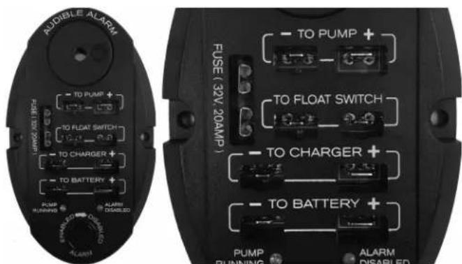
Terminal Block Connection
- Apply the double-sided tape to back of the terminal block (Figure 8).
- Press the terminal block onto the battery box where it will be accessible.
Alternately, two screws are provided for optional mounting away from battery box. - Complete wiring connections as directed in Table 2.
- Install 20 Amp fuse (provided) in terminal block.
text_image
AUDIBLE ALARM FUSE LOW (20AMP) TO PUMP + TO FLOAT SWITCH TO CHARGER + TO BATTERY + PUMP RUNNING ALARM DISABLED ALARM FUSE (32V 20AMP) TO PUMP + TO FLOAT SWITCH TO CHARGER + TO BATTERY + PUMP RUNNING ALARM DISABLEDFigure 8. Terminal Block
Table 2. Wiring Connections
| Connect Terminal Block | |
| Positive lead from Charger TO | CHARGER [+] connection |
| Negative lead from Charger TO | CHARGER [-] connection |
| Back-up pump Float Switch (2 wires) | TO FLOAT SWITCH connection (2 wires) |
| Positive lead from Pump TO PUMP | [+] connection |
| Negative lead from Pump TO PUMP | [-] connection |
Battery Connection
WARNING

RISK OF SERIOUS INJURY OR DEATH
■ Do not allow any person who is unqualified, to have contact with this pump system. Any person who is unaware of the dangers of this pump system, or has not read this manual, can easily be injured by the pump system.
WARNING

BATTERY HAZARDS
■ Never allow the battery DC terminals to touch each other. This can cause severe burns and start a fire. For added safety, protect the battery in provided battery box.

text_image
Liberty Pumps® MICROPROCESSOR CONTROLLED BATTERY CHARGER & MAINTAINER 12 VOLT 1 AMP Power Charging Ruff/Heat RustFigure 9. Battery Charger
- Install battery into the battery box.
-
Check polarity of battery posts. POSITIVE (POS.,P,+) battery post usually has a larger diameter than NEGATIVE (NEG.,N,-) post. Some batteries are equipped with 'Wing-Nut' terminals allowing for easy placement of the terminals to these posts.
-
Connect POSITIVE (RED) charger terminal lead to POSITIVE (POS.,P,+) battery post via access hole in battery box cover.
-
Tighten connection securely.
-
Connect the NEGATIVE (BLACK) charger terminal lead to NEGATIVE (NEG.,N,−) battery post via access hole in battery box cover.
-
Tighten connection securely. IMPORTANT: Do not face battery when making final connection.
-
Plug the charger into a 115/120 VAC electric outlet. IMPORTANT: Do not use a switch-controlled outlet.
-
Mark circuit in main power panel "Back-up sump pump power. supply; do not turn off".
-
With the charger properly connected and plugged in, the panel on the front of the charger will show the power and battery status.
Note: An alarm, located in the terminal block, automatically sounds when the system runs if the alarm is enabled. The alarm is silenced for 24 hrs when the ALARM DISABLED button is pressed.
-
Secure the battery in the box with the provided hold-down strap to prevent unwanted access to the battery.
-
When disconnecting charger, always do so in reverse sequence of connecting procedure and break first connection while as far away from battery as practical.
text_image
Not to ScaleFigure 10. Complete Back-up Pump System Example
The charger circuitry opens under severe overload. This condition may occur if attempting to charge any severely discharged or heavily sulfated battery. Once opened, the charger stops charging for a short period and then automatically resumes charging. The AMBER LED (Charging) will be OFF until charging resumes. Overloading could be due to an external load; remove the load condition prior to attempting to recharge the battery.
The charger has reverse battery and short circuit protection. If a reverse battery condition exists, unplug charger from AC power and reverse the connections.
The unit will automatically detect the battery internal cells condition as well as battery sulfated conditions.
The charger has internal overheat protection. The charger will turn off power until the temperature is down to a safe level, then automatically start charging again. All LEDs will be off.
The charger is designed to charge 12 V lead acid batteries.
- Never charge lithium ion batteries on this charger.
- The charge time is dependent on the Ah rating of the individual battery. See chart below.
line
| VOLTAGE | % OF CHARGE (%) | | :--- | :--- | | 11.5 V | 0 | | 11.9 V | 25 | | 12.3 V | 50 | | 12.7 V | 75 | | 13 V | 100 | *Approximate charge time 3–6 hours 5–11 hours 13–20 hours*Approximate charge time using a constant current charger at standard amps as specified on the battery. Charging times may vary depending on the Ah rating of the battery.
Charger Details
| Specifications | |
| Input Voltage 110–120 VAC | |
| Input Frequency | 50/60 Hz |
| Output | 1 A @ 12 VDC |
| Size without CableL x W x H | 3.9 x 2.7 x 1.4 in[105 x 68 x 35 mm] |
| Weight | 0.9 lbs [0.4 Kg] |
| Approvals | UL/cUL/FCC/BC/DOE |
| Environmental Characteristics | |
| Operating Temperature | 0 to 113°F [0 to 45°C] |
| Storage Temperature | -13 to 185°F [-25 to 85°C] |
| Operating Humidity Range | 0 to 90% RH |
| Cooling | Passive/Natural |
Charger Stages
| Stages | Explanation | LED Indication |
| Soft Start Change | Gently charges the battery using a reduced charge output until the battery voltages reaches 11.0 V. | Amber flashing |
| Bulk Charge | Charges using a constant maximum current (1 A) until the battery reaches 14.4 V. | Amber |
| Absorption Charge | Uses a constant voltage while reducing the charging output current to ensure the battery receives a full charge without overcharging the battery. | Amber |
| Full/Float | Battery is fully charged and is being maintained. | Green |
| Explanation | Power Charging | Full/Float | Fault | |
| Red LED | Amber LED | Green LED | Red LED | |
| AC Power connected, battery disconnected | ON OFF | OFF OFF | ||
| Soft Start Charge | ON FLASH OFF OFF | |||
| Bulk Charging | ON ON | OFF OFF | ||
| Absorption Charge | ON ON | OFF OFF | ||
| Fully Charged | ON OFF | ON OFF | ||
| Battery in reverse polarity connection | ON OFF | OFF ON | ||
| Battery Cells Shorted | ON OFF | OFF FLASH | ||
| Battery Bad Cells Detection | ON OFF | OFF FLASH | ||
| Battery Weak or Sulfated | ON OFF | FLASH OFF | ||
| AC Power OFF OFF OFF | OFF OFF | |||
Pump Maintenance
The pump should be checked frequently for debris and/or build-up that may interfere with pump or float switch operation. The float must be free to move without any restriction through its complete travel.
Periodically (at least every three months) test the pump to ensure proper function. This may be done by disconnecting power to the primary pump so that the water level rises to activate the back-up pump. Be sure to follow all safety precautions and remember to reconnect power to the primary pump and verify proper operation after conclusion of the test.
Charger Maintenance
To reduce risk of electric shock, unplug charger from AC outlet before attempting any maintenance or cleaning. Turning off controls will not reduce this risk.
Store in clean, dry place. Occasionally clean the case and cords with a dry cloth. No other maintenance is required. Do not disassemble charger, cord, or any associated part. Take it to a qualified service center when service or repair is required. Incorrect reassembly may result in a risk of electric shock or fire.
Battery Maintenance
Follow the battery manufacturer's recommendations for maintenance and safe use of battery.
Pump Troubleshooting
| Symptom Suggested Solution | |
| Pump will not run. | Check all wiring connections. |
| Check for low or defective battery. | |
| Confirm that the automatic switch is free to move up and down. | |
| Verify back-up switch is working properly. | |
| Check for a blown fuse in the terminal block. | |
| Pump cycles too frequently. | Improper float switch setting. Adjust distance between rubber stoppers on float rod to achieve desired pump cycle. |
| Main check valve located between discharge of primary pump and the back-up sump pump tee is not installed or is not working properly. Check all valves. Install or repair as required. | |
| Motor hums but pump will not run. | Check for low or defective battery. |
| Pump runs but pumps very little or no water. | Make sure a check valve is installed and functioning between the primary pump discharge and the back-up sump pump tee. Check all valves. Install or repair as required. |
| Check for obstruction in discharge pipe. | |
| Discharge pipe length and/or height exceeds capacity of pump. See Table 1 for pump capacity. | |
| Check for low or defective battery. | |
| Positive (+) and negative (−) battery wires are reversed. | |
| Ensure pump is not airlocked by orienting it at a 45° angle (Method C only). | |
Charger Troubleshooting
| Symptom/ LED Indication | Possible Causes | Suggested Solution | |
| Charger does not work | No LEDs ON | No AC power. Check AC connections and make sure power is switched ON. | |
| Charger has no DC output | Fault ON | Reverse polarity connection to battery. | Check that the spade terminals haven't fallen off the battery. |
| Check that the spade terminals are connected to the correct polarity. | |||
| No charging current | Fault flashing | Battery is severely sulfated or cannot hold a charge. | Replace battery. |
| Battery has a damaged cell. | Battery cannot be charged and must be replaced. | ||
| Full/ Float flashing | Battery is severely sulfated. | Check the battery condition, age, etc. Battery may need replacement. | |
Liberty Pumps Wholesale Products Limited Warranty
Liberty Pumps, Inc. warrants that Liberty Pumps wholesale products are free from all factory defects in material and workmanship for a period of three (3) years from the date of purchase (excluding batteries). The date of purchase shall be determined by a dated sales receipt noting the model and serial number of the pump. The dated sales receipt must accompany the returned pump if the date of return is more than three years from the date of manufacture noted on the pump nameplate.
The manufacturer's sole obligation under this Warranty shall be limited to the repair or replacement of any parts found by the manufacturer to be defective, provided the part or assembly is returned freight prepaid to the manufacturer or its authorized service center, and provided that none of the following warranty-voiding characteristics are evident:
The manufacturer shall not be liable under this Warranty if the product has not been properly installed, operated, or maintained per manufacturer instructions; if it has been disassembled, modified, abused, or tampered with; if the electrical cord has been cut, damaged, or spliced; if the pump discharge has been reduced in size; if the pump has been used in water temperatures above the advertised rating; if the pump has been used in water containing sand, lime, cement, gravel, or other abrasives; if the product has been used to pump chemicals, grease, or hydrocarbons; if a non-submersible motor has been subjected to moisture; or if the label bearing the model and serial number has been removed.
Liberty Pumps, Inc. shall not be liable for any loss, damage, or expenses resulting from installation or use of its products, or for indirect, incidental, and consequential damages, including costs of removal, reinstallation or transportation.
There is no other express warranty. All implied warranties, including those of merchantability and fitness for a particular purpose, are limited to three years from the date of purchase. This Warranty contains the exclusive remedy of the purchaser, and, where permitted, liability for consequential or incidental damages under any and all warranties are excluded.

7000 Apple Tree Avenue
Bergen, NY 14416
ph: 800-543-2550
fax: 585-494-1839
www.LibertyPumps.com