DCS690 - Saw DEWALT - Free user manual and instructions
Find the device manual for free DCS690 DEWALT in PDF.
Download the instructions for your Saw in PDF format for free! Find your manual DCS690 - DEWALT and take your electronic device back in hand. On this page are published all the documents necessary for the use of your device. DCS690 by DEWALT.
USER MANUAL DCS690 DEWALT
English (original instructions) Definitions: Safety Alert Symbols and Words This instruction manual uses the following safety alert symbols and words to alert you to hazardous situations and your risk of personal injury or property damage.
DANGER: Indicates an imminently hazardous situation which, if not avoided, will result in death or seriousinjury.
WARNING: Indicates a potentially hazardous situation which, if not avoided, could result in death or seriousinjury.
CAUTION: Indicates a potentially hazardous situation which, if not avoided, may result in minor or moderateinjury.
(Used without word) Indicates a safety related message. NOTICE: Indicates a practice not related to personal injury which, if not avoided, may result in propertydamage.
WARNING! Read all safety warnings and all instructions. Failure to follow the warnings and instructions may result in electric shock, fire and/or seriousinjury.
WARNING: To reduce the risk of injury, read the
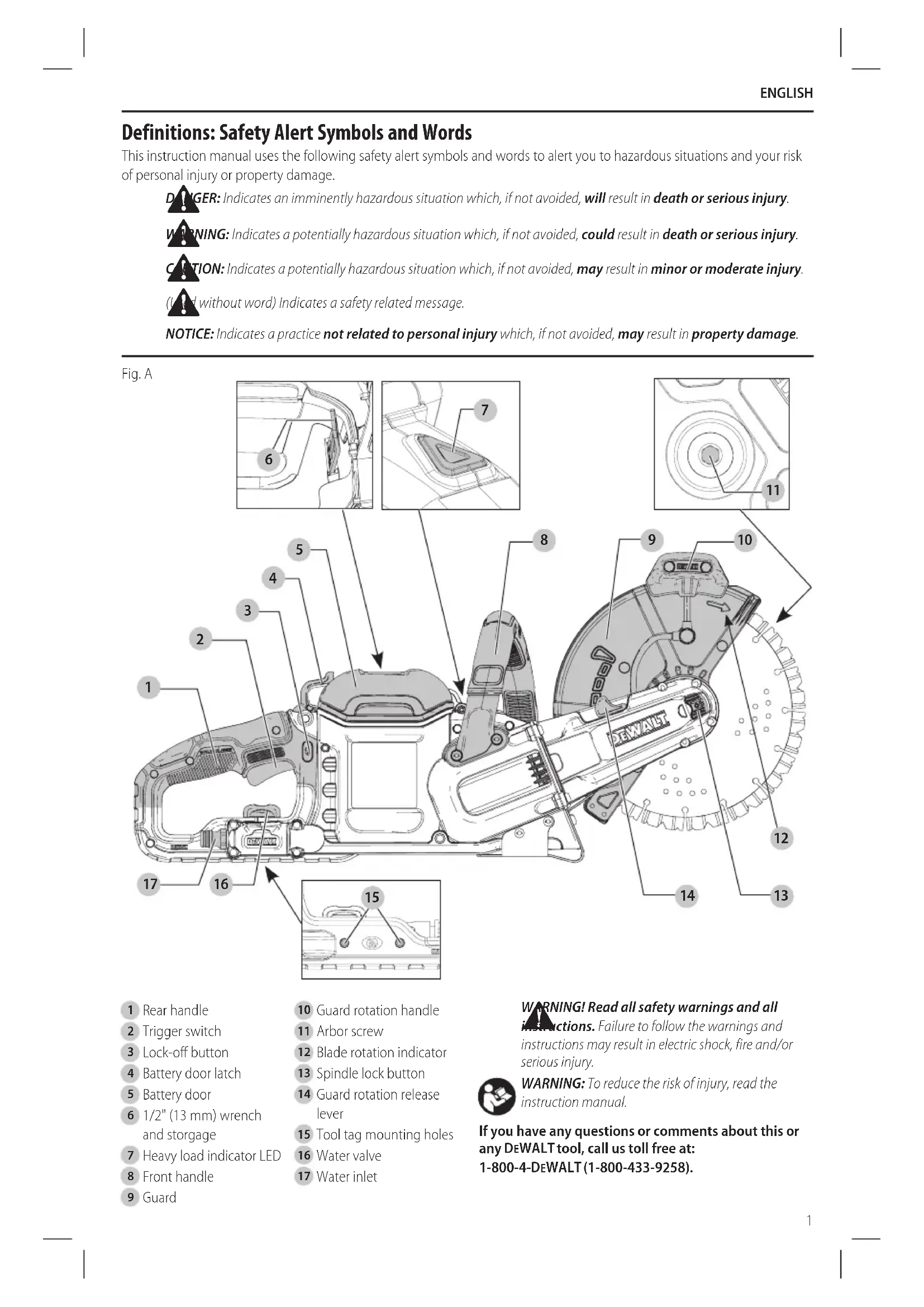
1/2" (13mm) wrench and storgage
Guard rotation release lever
Tool tag mounting holes
WARNING! Read all safety warnings and all instructions. Failure to follow the warnings and instructions may result in electric shock, fire and/or seriousinjury.
REFERENCE The term “power tool” in the warnings refers to your mains- operated (corded) power tool or battery-operated (cordless) powertool.
a ) Keep work area clean and well lit. Cluttered or dark areas inviteaccidents. b ) Do not operate power tools in explosive atmospheres, such as in the presence of flammable liquids, gases or dust. Power tools create sparks which may ignite the dust orfumes. c ) Keep children and bystanders away while operating a power tool. Distractions can cause you to losecontrol.
2) Electrical Safety
a ) Power tool plugs must match the outlet. Never modify the plug in any way. Do not use any adapter plugs with earthed (grounded) power tools. Unmodified plugs and matching outlets will reduce risk of electricshock. b ) Avoid body contact with earthed or grounded surfaces such as pipes, radiators, ranges and refrigerators. There is an increased risk of electric shock if your body is earthed orgrounded. c ) Do not expose power tools to rain or wet conditions. Water entering a power tool will increase the risk of electricshock. d ) Do not abuse the cord. Never use the cord for carrying, pulling or unplugging the power tool. Keep cord away from heat, oil, sharp edges or moving parts. Damaged or entangled cords increase the risk of electricshock. e ) When operating a power tool outdoors, use an extension cord suitable for outdoor use. Use of a cord suitable for outdoor use reduces the risk of electricshock. f ) If operating a power tool in a damp location is unavoidable, use a ground fault circuit interrupter (GFCI) protected supply. Use of a GFCI reduces the risk of electricshock.
a ) Stay alert, watch what you are doing and use common sense when operating a power tool. Do not use a power tool while you are tired or under the influence of drugs, alcohol or medication. A moment of inattention while operating power tools may result in serious personalinjury. b ) Use personal protective equipment. Always wear eye protection. Protective equipment such as dust mask, non-skid safety shoes, hard hat, or hearing protection used for appropriate conditions will reduce personalinjuries. c ) Prevent unintentional starting. Ensure the switch is in the off position before connecting to power source and/or battery pack, picking up or carrying the tool. Carrying power tools with your finger on the switch or energizing power tools that have the switch on invitesaccidents. d ) Remove any adjusting key or wrench before turning the power tool on. A wrench or a key left attached to a rotating part of the power tool may result in personalinjury. e ) Do not overreach. Keep proper footing and balance at all times. This enables better control of the power tool in unexpectedsituations. f ) Dress properly. Do not wear loose clothing or jewelry. Keep your hair, clothing and gloves away from moving parts. Loose clothes, jewelry or long hair can be caught in movingparts. g ) If devices are provided for the connection of dust extraction and collection facilities, ensure these are connected and properly used. Use of dust collection can reduce dust-relatedhazards.
4) Power Tool Use and Care
a ) Do not force the power tool. Use the correct power tool for your application. The correct power tool will do the job better and safer at the rate for which it wasdesigned. b ) Do not use the power tool if the switch does not turn it on and off. Any power tool that cannot be controlled with the switch is dangerous and must berepaired. c ) Disconnect the plug from the power source and/ or the battery pack from the power tool before making any adjustments, changing accessories, or storing power tools. Such preventive safety measures reduce the risk of starting the power toolaccidentally. d ) Store idle power tools out of the reach of children and do not allow persons unfamiliar with the power tool or these instructions to operate the power tool. Power tools are dangerous in the hands of untrainedusers. e ) Maintain power tools. Check for misalignment or binding of moving parts, breakage of parts and any other condition that may affect the power tool’s operation. If damaged, have the power tool repaired before use. Many accidents are caused by poorly maintained powertools. f ) Keep cutting tools sharp and clean. Properly maintained cutting tools with sharp cutting edges are less likely to bind and are easier tocontrol. g ) Use the power tool, accessories and tool bits, etc. in accordance with these instructions, takingEnglish
into account the working conditions and the work to be performed. Use of the power tool for operations different from those intended could result in a hazardoussituation.
5) Battery Tool Use and Care
a ) Recharge only with the charger specified by the manufacturer. A charger that is suitable for one type of battery pack may create a risk of fire when used with another batterypack. b ) Use power tools only with specifically designated battery packs. Use of any other battery packs may create a risk of injury andfire. c ) When battery pack is not in use, keep it away from other metal objects, like paper clips, coins, keys, nails, screws, or other small metal objects, that can make a connection from one terminal to another. Shorting the battery terminals together may cause burns or afire. d ) Under abusive conditions, liquid may be ejected from the battery; avoid contact. If contact accidentally occurs, flush with water. If liquid contacts eyes, additionally seek medical help. Liquid ejected from the battery may cause irritation orburns.
a ) Have your power tool serviced by a qualified repair person using only identical replacement parts. This will ensure that the safety of the power tool ismaintained. Additional Specific Safety Instructions for Cut-Off Machines a ) The guard provided with the tool must be securely attached to the power tool and positioned for maximum safety, so the least amount of wheel is exposed towards the operator. Position yourself and bystanders away from the plane of the rotating wheel. The guard helps to protect operator from broken wheel fragments and accidental contact withwheel. b ) Use only bonded reinforced wheels or diamond blades for your power tool. Just because an accessory can be attached to your power tool, it does not assure safeoperation. c ) The rated speed of the accessory must be at least equal to the maximum speed marked on the power tool. Accessories running faster than their rated speed can break and flyapart. d ) Wheels must be used only for recommended applications. For example: do not grind with the side of cut-off wheel. Abrasive cut-off wheels are intended for peripheral grinding, side forces applied to these wheels may cause them toshatter. e ) Always use undamaged wheel flanges that are of correct diameter for your selected wheel. Proper wheel flanges support the wheel thus reducing the possibility of wheelbreakage. f ) Do not use worn down reinforced wheels from larger power tools. Wheels intended for a larger power tool are not suitable for the higher speed of a smaller tool and mayburst. g ) The outside diameter and the thickness of your accessory must be within the capacity rating of your power tool. Incorrectly sized accessories cannot be adequately guarded orcontrolled. h ) The arbor size of wheels and flanges must properly fit the spindle of the power tool. Wheels and flanges with arbour holes that do not match the mounting hardware of the power tool will run out of balance, vibrate excessively and may cause loss ofcontrol. i ) Do not use damaged wheels. Before each use, inspect the wheels for chips and cracks. If power tool or wheel is dropped, inspect for damage or install an undamaged wheel. After inspecting and installing the wheel, position yourself and bystanders away from the plane of the rotating wheel and run the power tool at maximum no load speed for one minute. Damaged wheels will normally break apart during this testtime. j ) Wear personal protective equipment. Depending on application, use face shield, safety goggles or safety glasses. As appropriate, wear dust mask, hearing protectors, gloves and shop apron capable of stopping small abrasive or workpiece fragments. The eye protection must be capable of stopping flying debris generated by various operations. The dust mask or respirator must be capable of filtering particles generated by your operation. Prolonged exposure to high intensity noise may cause hearingloss. k ) Keep bystanders a safe distance away from work area. Anyone entering the work area must wear personal protective equipment. Fragments of workpiece or of a broken wheel may fly away and cause injury beyond immediate area ofoperation. l ) Hold the power tool by insulated gripping surfaces only, when performing an operation where the cutting accessory may contact hidden wiring. Cutting accessory contacting a "live" wire may make exposed metal parts of the power tool "live" and could give the operator an electricshock. m ) Never lay the power tool down until the accessory has come to a complete stop. The spinning wheel may grab the surface and pull the power tool out of yourcontrol. n ) Do not run the power tool while carrying it at your side. Accidental contact with the spinning accessory could snag your clothing, pulling the accessory into yourbody. o ) Regularly clean the power tool’s air vents. The motor’s fan will draw the dust inside the housing and excessive accumulation of powdered metal may cause electricalhazards.English
p ) Do not operate the power tool near flammable materials. Sparks could ignite thesematerials. Kickback and Related Warnings Kickback is a sudden reaction to a pinched or snagged rotating wheel. Pinching or snagging causes rapid stalling of the rotating wheel which in turn causes the uncontrolled power tool to be forced in the direction opposite of the wheel’s rotation at the point of thebinding. For example, if an abrasive wheel is snagged or pinched by the workpiece, the edge of the wheel that is entering into the pinch point can dig into the surface of the material causing the wheel to climb out or kick out. The wheel may either jump toward or away from the operator, depending on direction of the wheel’s movement at the point of pinching. Abrasive wheels may also break under theseconditions. Kickback is the result of power tool misuse and/or incorrect operating procedures or conditions and can be avoided by taking proper precautions as givenbelow. a ) Maintain a firm grip on the power tool and position your body and arm to allow you to resist kickback forces. Always hold front and rear handle for maximum control over kickback or torque reaction during start-up. The operator can control torque reactions or kickback forces, if proper precautions aretaken. b ) Never place your hand near the rotating accessory. Accessory may kickback over yourhand. c ) Do not position your body in line with the rotating wheel. Kickback will propel the tool in direction opposite to the wheel’s movement at the point ofsnagging. d ) Use special care when working corners, sharp edges etc. Avoid bouncing and snagging the accessory. Corners, sharp edges or bouncing have a tendency to snag the rotating accessory and cause loss of control orkickback. e ) Do not attach a saw chain, woodcarving blade or toothed saw blade on the saw. Such blades cause frequent kickback and loss ofcontrol. f ) Do not use a segmented wheel with a peripheral gap greater than 3/8" (10mm). g ) Do not "jam" the wheel or apply excessive pressure. Do not attempt to make an excessive depth of cut. Overstressing the wheel increases the loading and susceptibility to twisting or binding of the wheel in the cut and the possibility of kickback or wheelbreakage. h ) When wheel is binding or when interrupting a cut for any reason, switch off the power tool and hold the power tool motionless until the wheel comes to a complete stop. Never attempt to remove the wheel from the cut while the wheel is in motion otherwise kickback may occur. Investigate and take corrective action to eliminate the cause of wheelbinding. i ) Do not restart the cutting operation in the workpiece. Let the wheel reach full speed and carefully re-enter the cut. The wheel may bind, walk up or kickback if the power tool is restarted in theworkpiece. j ) Support panels or any oversized workpiece to minimize the risk of wheel pinching and kickback. Large workpieces tend to sag under their own weight. Supports must be placed under the workpiece near the line of cut and near the edge of the workpiece on both sides of thewheel. k ) Use extra caution when making a “pocket cut” into existing walls or other blind areas. The protruding wheel may cut gas or water pipes, electrical wiring or objects that can causekickback. Additional Safety Information
- Use of accessories not specified in this manual is not recommended and may be hazardous. Use of power boosters that would cause the tool to be driven at speeds greater than its rated speed constitutesmisuse.
- Do not use circular saw blades with this tool. Serious injury mayresult.
- Avoid bouncing the wheel or giving it rough treatment. If this occurs, stop the tool and inspect the wheel for cracks orflaws.
- Direct sparks away from operator, bystanders or flammable materials. Sparks may be produced while using a cut-off tool. Sparks may cause burns or startfires.
- Always use front handle. Make sure the front handle is securely tightened before use. The front handle should always be used to maintain control of the tool at alltimes.
- Never cut into area that may contain electrical wiring or piping. Serious injury mayresult.
- Clean out your tool often, especially after heavy use. Dust and grit containing metal particles often accumulate on interior surfaces and could create an electric shockhazard.
- Do not operate this tool for long periods of time. Vibration caused by tool action may be harmful to your hands and arms. Use gloves to provide extra cushion and limit exposure by taking frequent restperiods.
- Never use the weight of the tool to stop bladerotation.
- Never leave your cut-off machine unattended if it is in operating mode. When your cut-off machine is not in use, remove the battery pack, make sure the trigger switch is in the OFF position and lock-off button isengaged.
- Always wear sturdy boots with non-slip soles and heavy-duty work gloves when operating your cut-off machine. Heavy-duty gloves improve your grip and protect yourhands.
- Always use NIOSH/OSHA approved respiratory protection when wet cutting below the recommended flowrate.
- Consult and follow any federal, state or local laws or regulations with respect to dry and wetcutting.English
- Never touch the rotating wheel with any part of yourbody.
- When transporting the machine always make sure the lock-off button is in the lockedposition.
- Remove the cutting wheel after use. The cutting wheel may suffer damage duringtransport.
- Never use a cutting wheel that is damaged, is untrue orvibrates.
- Never use your cut-off machine while standing on a ladder orscaffolding.
- Never cut above your shoulderheight.
- Do not cut wood or any material from which the cutting wheel is notrated.
- Use the wet cut method when using a diamond blade whenever possible. The water can act as a lubricant and reduce the risk reactiveforces.
- Use caution when reentering a cut. Do not push the cutting wheel into the cut at an angle as this can increase the risk onbinding.
- Always be alert of anything that could cause the workpiece to close at the cut and pinch the cutting wheel. Always support the workpiece in a manner that results in the cut remaining open. Never make a cut that could result in binding of the cuttingwheel.
WARNING: ALWAYS use safety glasses. Everyday
eyeglasses are NOT safety glasses. Also use face or dust mask if cutting operation is dusty. ALWAYS WEAR CERTIFIED SAFETYEQUIPMENT:
WARNING: Some dust created by power sanding,
sawing, grinding, drilling, and other construction activities contains chemicals known to the State of California to cause cancer, birth defects or other reproductive harm. Some examples of these chemicalsare:
- lead from lead-based paints,
- crystalline silica from bricks and cement and other masonry products, and
- arsenic and chromium from chemically- treatedlumber. Your risk from these exposures varies, depending on how often you do this type of work. To reduce your exposure to these chemicals: work in a well ventilated area, and work with approved safety equipment, such as those dust masks that are specially designed to filter out microscopicparticles.
- Avoid prolonged contact with dust from power sanding, sawing, grinding, drilling, and other construction activities. Wear protective clothing and wash exposed areas with soap and water. Allowing dust to get into your mouth, eyes, or lay on the skin may promote absorption of harmfulchemicals.
WARNING: Use of this tool can generate and/
or disperse dust, which may cause serious and permanent respiratory or other injury. Always use NIOSH/OSHA approved respiratory protection appropriate for the dust exposure. Direct particles away from face andbody.
WARNING: Always wear proper personal hearing
protection that conforms to ANSI S12.6 (S3.19) during use. Under some conditions and duration of use, noise from this product may contribute to hearingloss.
CAUTION: When not in use, place tool on its side on a stable surface where it will not cause a tripping or falling hazard. Some tools with large battery packs will stand upright on the battery pack but may be easily knockedover.
- Air vents often cover moving parts and should be avoided. Loose clothes, jewelry or long hair can be caught in movingparts. The label on your tool may include the following symbols. The symbols and their definitions are asfollows: V ......................... volts Hz .......................hertz min ..................... minutes or DC ......direct current ...................... Class I Construction (grounded) …/min ..............per minute BPM .................... beats per minute IPM ..................... impacts per minute RPM .................... revolutions per minute sfpm ................... surface feet per minute SPM .................... strokes per minute A ......................... amperes W ........................watts or AC ...........alternating current or AC/DC .... alternating or direct current ...................... Class II Construction (double insulated)
The battery pack is not fully charged out of the carton. Before using the battery pack and charger, read the safety instructions below and then follow charging proceduresoutlined. When ordering replacement battery packs, be sure to include the catalog number andvoltage. Your tool uses a DeWALT charger. Be sure to read all safety instructions before using your charger. Consult the chart at the end of this manual for compatibility of chargers and batterypacks.
READ ALL INSTRUCTIONS
Important Safety Instructions for All Battery Packs
WARNING: Read all safety warnings and all
instructions for the battery pack, charger and power tool. Failure to follow the warnings and instructions may result in electric shock, fire and/ or seriousinjury.ENGLISH
- Do not charge or use the battery pack in explosive atmospheres, such as in the presence of flammable liquids, gases or dust. Inserting or removing the battery pack from the charger may ignite the dust orfumes.
- NEVER force the battery pack into the charger. DO NOT modify the battery pack in any way to fit into a non-compatible charger as battery pack may rupture causing serious personal injury. Consult the chart at the end of this manual for compatibility of batteries andchargers.
- Charge the battery packs only in designated DeWALT chargers.
- DO NOT splash or immerse in water or otherliquids.
- Do not store or use the tool and battery pack in locations where the temperature may reach or exceed 104°F (40°C) (such as outside sheds or metal buildings in summer). For best life store battery packs in a cool, drylocation. NOTE: Do not store the battery packs in a tool with the trigger switch locked on. Never tape the trigger switch in the ONposition.
- Do not incinerate the battery pack even if it is severely damaged or is completely worn out. The battery pack can explode in a fire. Toxic fumes and materials are created when lithium ion battery packs areburned.
- If battery contents come into contact with the skin, immediately wash area with mild soap and water. If battery liquid gets into the eye, rinse water over the open eye for 15 minutes or until irritation ceases. If medical attention is needed, the battery electrolyte is composed of a mixture of liquid organic carbonates and lithiumsalts.
- Contents of opened battery cells may cause respiratory irritation. Provide fresh air. If symptoms persist, seek medicalattention.
WARNING: Burn hazard. Battery liquid may be
flammable if exposed to spark orflame.
WARNING: Fire hazard. Never attempt to open the
battery pack for any reason. If the battery pack case is cracked or damaged, do not insert into the charger. Do not crush, drop or damage the battery pack. Do not use a battery pack or charger that has received a sharp blow, been dropped, run over or damaged in any way (e.g., pierced with a nail, hit with a hammer, stepped on). Damaged battery packs should be returned to the service center forrecycling. Transportation
WARNING: Fire hazard. Do not store or carry the
battery pack so that metal objects can contact exposed battery terminals. For example, do not place the battery pack in aprons, pockets, tool boxes, product kit boxes, drawers, etc., with loose nails, screws, keys, etc. Transporting batteries can possibly cause fires if the battery terminals inadvertently come in contact with conductive materials such as keys, coins, hand tools and the like. The US Department of Transportation Hazardous Material Regulations (HMR) actually prohibit transporting batteries in commerce or on airplanes in carry-on baggage UNLESS they are properly protected from short circuits. So when transporting individual battery packs, make sure that the battery terminals are protected and well insulated from materials that could contact them and cause a shortcircuit. Shipping the DeWALT FLEXVOLT™ Battery The D
WALT FLEXVOLT™ battery has two modes: Use andShipping. Use Mode: When the FLEXVOLT™ battery stands alone or is in a D
WALT 20V Max* product, it will operate as a 20V Max* battery. When the FLEXVOLT™ battery is in a 60V Max* or a 120V Max* (two 60V Max* batteries) product, it will operate as a 60V Max* battery. Shipping Mode: When the cap is attached to the FLEXVOLT™ battery, the battery is in Shipping Mode. Strings of cells are electrically disconnected within the pack resulting in three batteries with a lower Watt hour (Wh) rating as compared to one battery with a higher Watt hour rating. This increased quantity of three batteries with the lower Watt hour rating can exempt the pack from certain shipping regulations that are imposed upon the higher Watt hourbatteries. The battery label indicates two Watt hour ratings (see example). Depending on how the battery is shipped, the appropriate Watt hour rating must be used to determine the applicable shipping requirements. If utilizing the shipping cap, the pack will be considered 3 batteries at the Watt hour rating indicated for “Shipping”. If shipping without the cap or in a tool, the pack will be considered one battery at the Watt hour rating indicated next to “Use”. USE: 120 Wh Shipping: 3 x 40 Wh Example of Use and Shipping Label Marking For example, Shipping Wh rating might indicate 3 x 40 Wh, meaning 3 batteries of 40 Watt hours each. The Use Wh rating might indicate 120 Wh (1 batteryimplied). Fuel Gauge Battery Packs (Fig. B) Some DeWALT battery packs include a fuel gauge which consists of three green LED lights that indicate the level of charge remaining in the batterypack. The fuel gauge is an indication of approximate levels of charge remaining in the battery pack according to the followingindicators: 75–100% charged 51–74% charged < 50% charged Pack needs to be charged To actuate the fuel gauge, press and hold the fuel gauge button. A combination of the three green LED lights will illuminate designating the level of charge left. When theENGLISH
level of charge in the battery is below the usable limit, the fuel gauge will not illuminate and the battery will need to berecharged. Fig. B NOTE: The fuel gauge is only an indication of the charge left on the battery pack. It does not indicate tool functionality and is subject to variation based on product components, temperature and end-userapplication. For more information regarding fuel gauge battery packs, please contact call 1-800-4- DeWALT (1-800-433-9258) or visit our website www.dewalt.com. The RBRC® Seal The RBRC® (Rechargeable Battery Recycling Corporation) Seal on the nickel cadmium, nickel metal hydride or lithium- ion batteries (or battery packs) indicates that the costs to recycle these batteries (or battery packs) at the end of their useful life have already been paid by DeWALT . In some areas, it is illegal to place spent nickel cadmium, nickel metal hydride or lithium-ion batteries in the trash or municipal solid waste stream and the Call2Recycle® program provides an environmentally consciousalternative. Call 2 Recycle, Inc., in cooperation with DeWALT and other battery users, has established the program in the United States and Canada to facilitate the collection of spent nickel cadmium, nickel metal hydride or lithium-ion batteries. Help protect our environment and conserve natural resources by returning the spent nickel cadmium, nickel metal hydride or lithium-ion batteries to an authorized DeWALT service center or to your local retailer for recycling. You may also contact your local recycling center for information on where to drop off the spent battery. RBRC® is a registered trademark of Call 2 Recycle,Inc. Important Safety Instructions for All Battery Chargers
WARNING: Read all safety warnings and all
instructions for the battery pack, charger and power tool. Failure to follow the warnings and instructions may result in electric shock, fire and/ or seriousinjury.
- DO NOT attempt to charge the battery pack with any chargers other than the ones in this manual. The charger and battery pack are specifically designed to worktogether.
- These chargers are not intended for any uses other than charging DeWALT rechargeable batteries. Any other uses may result in risk of fire, electric shock orelectrocution.
- Do not expose the charger to rain orsnow.
- Pull by the plug rather than the cord when disconnecting the charger. This will reduce the risk of damage to the electric plug andcord.
- Make sure that the cord is located so that it will not be stepped on, tripped over or otherwise subjected to damage orstress.
- Do not use an extension cord unless it is absolutely necessary. Use of improper extension cord could result in risk of fire, electric shock orelectrocution.
- When operating a charger outdoors, always provide a dry location and use an extension cord suitable for outdoor use. Use of a cord suitable for outdoor use reduces the risk of electricshock.
- An extension cord must have adequate wire size (AWG or American Wire Gauge) for safety. The smaller the gauge number of the wire, the greater the capacity of the cable, that is, 16 gauge has more capacity than 18 gauge. An undersized cord will cause a drop in line voltage resulting in loss of power and overheating. When using more than one extension to make up the total length, be sure each individual extension contains at least the minimum wire size. The following table shows the correct size to use depending on cord length and nameplate ampere rating. If in doubt, use the next heavier gauge. The lower the gauge number, the heavier thecord. Minimum Gauge for Cord Sets Volts Total Length of Cord in Feet (meters) 120 V 25 (7.6) 50 (15.2) 100 (30.5) 150 (45.7) 240 V 50 (15.2) 100 (30.5) 200 (61.0) 300 (91.4) Ampere Rating American Wire Gauge More Than Not More Than
- Do not place any object on top of the charger or place the charger on a soft surface that might block the ventilation slots and result in excessive internal heat. Place the charger in a position away from any heat source. The charger is ventilated through slots in the top and the bottom of thehousing.
- Do not operate the charger with a damaged cord orplug.
- Do not operate the charger if it has received a sharp blow, been dropped or otherwise damaged in any way. Take it to an authorized servicecenter.
- Do not disassemble the charger; take it to an authorized service center when service or repair is required. Incorrect reassembly may result in a risk of electric shock, electrocution orfire.
- Disconnect the charger from the outlet before attempting any cleaning. This will reduce the risk of electric shock. Removing the battery pack will not reduce thisrisk.
- NEVER attempt to connect 2 chargerstogether.
- The charger is designed to operate on standard 120V household electrical power. Do not attempt toENGLISH
use it on any other voltage. This does not apply to the vehicularcharger.
WARNING: Shock hazard. Do not allow any liquid to
WARNING: Burn hazard. Do not submerge the
battery pack in any liquid or allow any liquid to enter the battery pack. Never attempt to open the battery pack for any reason. If the plastic housing of the battery pack breaks or cracks, return to a service center forrecycling.
CAUTION: Burn hazard. To reduce the risk of injury, charge only DeWALT rechargeable battery packs. Other types of batteries may overheat and burst resulting in personal injury and propertydamage. NOTICE: Under certain conditions, with the charger plugged into the power supply, the charger can be shorted by foreign material. Foreign materials of a conductive nature, such as, but not limited to, grinding dust, metal chips, steel wool, aluminum foil or any buildup of metallic particles should be kept away from the charger cavities. Always unplug the charger from the power supply when there is no battery pack in the cavity. Unplug the charger before attempting toclean. Charging a Battery (Fig. C)
1. Plug the charger into an appropriate outlet before
inserting batterypack.
into the charger, making sure the battery pack is fully seated in the charger. The red (charging) light will blink continuously indicating that the charging process hasstarted.
3. The completion of charge will be indicated by the red
light remaining ON continuously. The battery pack is fully charged and may be used at this time or left in the charger. To remove the battery pack from the charger, push the battery release button
on the batterypack. NOTE: To ensure maximum performance and life of lithium- ion battery packs, charge the battery pack fully before firstuse. Charger Operation Refer to the indicators below for the charge status of the batterypack.
DCB107, DCB112, DCB113, DCB115, DCB118, DCB132
Charging Fully Charged Hot/Cold Pack Delay*
- DCB107, DCB112, DCB113, DCB115, DCB118, DCB132: The red light will continue to blink, but a yellow indicator light will be illuminated during this operation. Once the battery pack has reached an appropriate temperature, the yellow light will turn off and the charger will resume the chargingprocedure. The compatible charger(s) will not charge a faulty battery pack. The charger will indicate faulty battery pack by refusing to light or by displaying a problem pack or charger blinkpattern. NOTE: This could also mean a problem with acharger. If the charger indicates a problem, take the charger and battery pack to be tested at an authorized servicecenter. Hot/Cold Pack Delay When the charger detects a battery pack that is too hot or too cold, it automatically starts a Hot/Cold Pack Delay, suspending charging until the battery pack has reached an appropriate temperature. The charger then automatically switches to the pack charging mode. This feature ensures maximum battery packlife. A cold battery pack will charge at a slower rate than a warm battery pack. The battery pack will charge at that slower rate throughout the entire charging cycle and will not return to maximum charge rate even if the battery packwarms. The DCB118 charger is equipped with an internal fan designed to cool the battery pack. The fan will turn on automatically when the battery pack needs to becooled. Never operate the charger if the fan does not operate properly or if ventilation slots are blocked. Do not permit foreign objects to enter the interior of thecharger. Electronic Protection System Li-Ion tools are designed with an Electronic Protection System that will protect the battery pack against overloading, overheating or deepdischarge. The tool will automatically turn off if the Electronic Protection System engages. If this occurs, place the lithium- ion battery pack on the charger until it is fullycharged. Wall Mounting
DCB107, DCB112, DCB113, DCB115, DCB118, DCB132
These chargers are designed to be wall mountable or to sit upright on a table or work surface. If wall mounting, locate the charger within reach of an electrical outlet, and away from a corner or other obstructions which may impede air flow. Use the back of the charger as a template for the location of the mounting screws on the wall. Mount the charger securely using drywall screws (purchasedEnglish
separately) at least 1" (25.4 mm) long, with a screw head diameter of 0.28–0.35" (7–9mm), screwed into wood to an optimal depth leaving approximately 7/32" (5.5 mm) of the screw exposed. Align the slots on the back of the charger with the exposed screws and fully engage them in theslots. Charger Cleaning Instructions
WARNING: Shock hazard. Disconnect the charger
from the AC outlet before cleaning. Dirt and grease may be removed from the exterior of the charger using a cloth or soft non-metallic brush. Do not use water or any cleaningsolutions. Important Charging Notes
1. Longest life and best performance can be obtained if
the battery pack is charged when the air temperature is between 65°F and 75°F (18° – 24°C). DO NOT charge the battery pack in an air temperature below +40°F (+4.5°C), or above +104°F (+40°C). This is important and will prevent serious damage to the batterypack.
2. The charger and battery pack may become warm to the
touch while charging. This is a normal condition, and does not indicate a problem. To facilitate the cooling of the battery pack after use, avoid placing the charger or battery pack in a warm environment such as in a metal shed or an uninsulatedtrailer.
3. If the battery pack does not charge properly:
a. Check operation of receptacle by plugging in a lamp or other appliance; b. Check to see if receptacle is connected to a light switch which turns power off when you turn out the lights; c. Move the charger and battery pack to a location where the surrounding air temperature is approximately 65°F – 75°F (18° – 24°C); d. If charging problems persist, take the tool, battery pack and charger to your local servicecenter.
4. The battery pack should be recharged when it fails to
produce sufficient power on jobs which were easily done previously. DO NOT CONTINUE to use under these conditions. Follow the charging procedure. You may also charge a partially used pack whenever you desire with no adverse effect on the batterypack.
5. Foreign materials of a conductive nature such as, but
not limited to, grinding dust, metal chips, steel wool, aluminum foil, or any buildup of metallic particles should be kept away from charger cavities. Always unplug the charger from the power supply when there is no battery pack in the cavity. Unplug the charger before attempting toclean.
6. Do not freeze or immerse the charger in water or any
otherliquid. Storage Recommendations
1. The best storage place is one that is cool and dry, away
from direct sunlight and excess heat orcold.
2. For long storage, it is recommended to store a fully
charged battery pack in a cool dry place out of the charger for optimalresults. nOTE: Battery packs should not be stored completely depleted of charge. The battery pack will need to be recharged beforeuse.
SAVE THESE INSTRUCTIONS FOR
of it. Damage or personal injury couldresult. Refer to Figure A at the beginning of this manual for a complete list ofcomponents. Intended Use This cut off tool is designed for professional cuttingapplications. DO nOT use under wet conditions or in presence of flammable liquids orgases. This cut off tool is a professional power tool. DO nOT let children come into contact with the tool. Supervision is required when inexperienced operators use thistool. SPECIFICATIONS DCs690 Blade diameter 9" (230 mm) Arbor size 7/8" (22.2 mm) RPM 6600 Lock-Off Button (Fig. A) Your cut-off tool is equipped with a lock-off button
To lock the trigger switch in the OFF postition, push the lock-off button from the left side of the tool. To unlock the trigger switch, push the lock-off button from the right side of thetool.
ASSEMBLY AND ADJUSTMENTS
WARNING: To reduce the risk of serious personal
injury, turn unit off and remove the battery pack before making any adjustments or removing/ installing attachments or accessories. Make sure the trigger switch is in the OFFposition. An accidental start-up can causeinjury. Spindle Lock Button (Fig. A) The spindle lock button
is used to lock the arbor screw
when changingaccessories.
1. To engage the spindle lock button, remove the battery
pack and make sure trigger switch is in the OFF position and lock-off button isengaged.
2. Depress the spindle lock button and turn the wheel and
spindle until the lock button engages thespindle.
to unscrew the arbor screw
and remove or mount accessories. Spindle threads are righthand.English
Installing Abrasive and Diamond Wheels (Fig. A, D)
WARNING: Install only oneblade.1. Lay unit on a firm surface, with the arbor screw
facingupward.2. Using supplied 1/2" (13mm) open end wrench
(located in the battery compartment), remove arbor screw , outer clamp washer and used wheel
if one is installed. Hold arbor screw from turning with spindle lock button . Spindle threads are righthand.3. The inner clamp washer is held in place with a double D shaft and retainingring.4. Slip wheel over spindle . Slip on outer clamp washer. Start threading on arbor screw which will self align outer clampwasher. iMPORTAnT: Make sure the diamond blade is installed with the correct rotation, as marked on the blade rotation indicator
5. Engage spindle lock button and tighten screw firmly with wrench. Do not over-tighten arborscrew.6. Turn wheel by hand to ensure it is properly centered. The wheel should not hit the shoe or guard. The screw and flanges should betight. CAUTION: Only use 9" (230mm) Type 1/41 wheels with 7/8" (22.2mm) arbor hole with this tool. Never force a wheel onto the machine or alter the size of the arborhole.
WARNING: Replace clamp washers as they wear. They may become sharp with extendeduse.1. Remove the arbor screw
, outer clamp washer
and used wheel if one is installed as described in Installing Abrasive and DiamondWheels.2. To remove the inner clamp washer , first remove the retainingring that holds the inner clamp washer to the double Dshaft.3. Remove the inner clamp washer and replace with a new one. Orient the inner clamp washer with the depressed center section toward the blade. Make sure the new inner clamp washer is secure with the retaining ring inplace.4. Install the wheel , new outer clamp washer , and arbor screw as described in Installing Abrasive and DiamondWheels. Adjusting the Guard Angle (Fig. E)
WARNING: Do not use guard rotation handle to hold tool while cutting. Guard rotation handle is only used for adjustment of the guard while tool is not inuse. CAUTION: Guard may be hot. Use guard handle to rotateguard. WARNING: Always make sure the guard is properly engaged before starting themachine.You can adjust the angle of theguard.1. To adjust the angle of the guard, pull back the guard rotation release lever and holdit.2. Grasp the guard firmly by guard rotation handle
and rotate to desiredangle.3. Release the guard rotation release lever and make sure it engages, locking the guard in place. If the guard rotation release lever doesn't engage, rotate the guard slightly until the guard rotation release lever returns to the lockedposition. Fig. E
DeWALT Tool Tag Ready (Fig. F) Optional Accessory Your cut-off saw comes with mounting holes and fasteners for installing a DeWALT Tool Tag. You will need a T15 bit tip to install the tag. The DeWALT Tool Tag is designed for tracking and locating professional power tools, equipment, and machines using the DeWALT Tool Connect™ app. For proper installation of the DeWALT Tool Tag refer to the DeWALT Tool Tagmanual.English
WARNING: To reduce the risk of serious personal
injury, turn unit off and remove the battery pack before making any adjustments or removing/ installing attachments or accessories. Make sure the trigger switch is in the OFFposition. An accidental start-up can causeinjury. Installing and Removing the Battery Pack (Fig. G) nOTE: For best results, make sure your battery pack is fullycharged. Use only DeWALT FLEXVOLT™ batteries with this cut-offmachine. Unlock battery door
by moving battery door latch
towards the rear of the tool and open as shown in Figure G. To install the battery pack
into the tool, align the battery pack with the rails inside the tool and slide it in until the battery pack is firmly seated. Ensure that it does notdisengage. Close the battery door
, and push the battery door latch
forward towards the front of the tool to lock the batterydoor. To remove the battery pack from the tool, unlatch and open the battery door. Then press the battery release button
and firmly pull the battery pack out of the tool. Insert it into the charger as described in Charging aBattery. Do not leave the battery dooropen.
WARNING: To reduce the risk of serious personal injury,
WARNING: To reduce the risk of serious personal
injury, ALWAYS hold securely in anticipation of a suddenreaction.
WARNING: Never use the cut-off machine with one
hand. Always grip the cut-off machine firmly with bothhands.
WARNING: Make sure the handles and grips of
your cut-off machine are secure and free of grease and/ormoisture. Proper hand position for both left- and right-handed users requires your right hand on the rear handle
and your left hand on the front handle
will illuminate as a warning when the tool is being pushed too hard. Continuing to use the tool after the LED is lit could cause the tool to shut down or reduce runtime. Reducing the Risk of Kickback (Fig. I)
WARNING: Reactive forces may occur at any time
the cutting wheel is inmotion.
WARNING: To reduce the risk of kickback, avoid
cutting with the upper quadrant of the cutting wheel whenever possible. Be extremely mindful of binding or pinching of the cutting wheel in this area as it can cause severe reactive forces resulting inkickback.
- Always be alert to any potential movement that could cause the material being cut to close and pinch the cuttingwheel.
- Proper support of the material will ensure the cut stays open during the cut. If you cannot properly support the material, do not use a cut-off machine to make yourcut. Fig. I
- Always support exposed pipe in the ground so that it is stable and is able to support weight. Use additionalENGLISH
support closer to the area to be cut to prevent the pipe from sagging and pinching the cuttingwheel.
- Material that is under stress could shift when it is cut. Uneven pipe beds could exertstress.
- Always make sure the section of material being removed is also supported. After the first cut is made you may have to move supports or add additional support to ensure both sides of the material are evenlysupported.
- Be aware of weakened work areas that could shift or slide causing your supports tomove. Making Cuts with a Cut-Off Machine
CAUTION: Before attempting to start, grasp tool firmly with both hands beforelifting.
WARNING: Cut-off saw not intended for surface
grinding or other applications where side loading of the blade isencountered.
WARNING: Edge cutting can be performed only
with wheels that are designed and specified for this purpose. Protect yourself during edge cutting by directing the open side of the guard away from you, theoperator.
WARNING: Wheels used for cutting may break or kick
back if they bend or twist while the tool is being used to do cut-offwork.
WARNING: Always be alert for gyroscopic forces that
can be generated by a rapidly spinning cutting wheel. Moving the cut-off machine sideways can create a gyroscopic force, causing the operator to experience an unexpected perpendicular change indirection. Wet Cut Method (Fig. A, J, K)
CAUTION: Close battery door and securely latch it closed before using anywater.
CAUTION: Never use the saw over head. When using water, limit cutting to the horizontal position to reduce the risk of water entering thetool.
WARNING: Wet cut method is to be used only with
WARNING: The recommended flow rate should be at
least 20 fl. oz. (0.6 liters) per minute. Cutting at a flow rate less than recommended or cutting for more than two consecutive hours requires use of NIOSH/OSHA approved respiratory protection for the operator and anybystanders.
WARNING: Maximum supplied water pressure not to
WARNING: Makes sure that water does not flow onto
the abrasive wheel while the cut-off machine is not in use. The cutting wheel will absorb water which will affect thebalance. NOTICE: Before using the wet cut method, make sure water will not damage the material being cut or surroundingproperty. Attaching the Water Supply
1. Attach the water supply to the quick water
2. Attach the quick water connector to the water inlet
3. To regulate the water flow, slowly rotate the water
towards to open position until desired flow is reached as shown in Figure K. To stop the flow of water, rotate the water valve to the closedpostion.
4. Proceed to cut as described in Making a Cutbelow.
5. After finishing your cuts, run the machine for
3–5seconds with the water valve closed to remove any residual water from the cuttingwheel. OPEN CLOSED Fig. K
Removing the Water Supply
1. Turn off and depressurize watersystem.
2. Make sure the trigger switch
is in the OFF position and lock-off button
3. Close the water valve
4. Disconnect the quick water connector
from the water inlet
WARNING: Always make sure the guard is in place
and set for the type of cut you are making.
WARNING: Always use your cut-off machine so that
the operator and bystanders are not endangered by potential airborne particles of material being cut, sparks, or pieces of damaged cuttingwheels.
DANGER: To reduce the risk of serious or fatal injury,
DO NOT change direction during the cut. A change in direction may produce a high torsional load on the cutting wheel and cause it to bind or break.
1. Mark a cutting line on the material to becut.
2. Grasp rear handle
3. Line up wheel with cutting line. Be sure nothing is near
or in line with thewheel.
4. Depress and hold trigger switch
, wait for the blade to reach full speed, then slowly feed wheel into work with firm pressure, working along the cutting line. Do not force the tool. Cut only as deep as needed to reduce the amount of dust produced. For maximum efficiency and wheel life, keep the wheel speedhigh. To maintain control of the cut-off machine, release pressure as you near the end of yourcut.
5. To stop tool, release trigger switch
6. Set the lock-off button
to the locked postion and make sure the cutting wheel has come to a complete stop before setting the cut-off machinedown. NOTE: Denser and thicker material should be cut in several passes. The maximum depth of cut of each pass should not exceed 1.0" (25.4mm). Cutting Slabs (Fig. L, M)
WARNING: Before making any cuts, make sure the
slab is properly secured on a non-slipsurface.
1. Cut a guiding groove along a marked cuttingline.
2. Cut deeper into the slab, never exceeding the maximum
depth of cut of 3.25" (83mm), and leaving a ridge of uncut material
as shown on Fig.L. Fig. L
3. Cut through the slab at each end to ensure the slab
NOTE: Curves must be made into the slab using several straight cuts as shown in Fig. M, always making sure that the cutting wheel does not becomewedged. Fig. M Cutting Pipe (Fig. N, O)
WARNING: Before making any cuts, make sure the
pipe is properly secured on a non-slipsurface.
WARNING: Pipe may break at any time during the
cut. Take precautions to maintain control of the tool and avoid fallingdebris. If the outer diameter of the pipe is smaller than the maximum cutting depth
- Make one cut straight down, starting at the top of the pipe through to the bottom of thepipe. If the outer diameter of the pipe is larger than the maximum cutting depth Several cuts are needed on larger pipes and it is important to make the cuts in the propersequence. If the pipe is in-ground and can not be rolled, make the following sequence of cuts
1. Cut a guiding groove along a marked cutting line
making sure to avoid any metal reinforcements ifpossible.
2. Start at the bottom of the pipe and use only the front
and upper part of the cutting wheel. This will reduce the risk of kickback orpinching.
3. Using only the front and upper part of the cutting
wheel, make a cut on the oppsite lower side of thepipe.
4. Make a lateral cut on the top half of thepipe.
5. Make a second lateral cut on the opposite side of the
top half. IMPORTANT: To keep the pipe from pinching the cutting wheel, make sure not to cut into the area of the finalcut.
6. Make sure all the top and bottom cuts are complete
when making the final topcut. IMPORTANT: Always make the final cut from the top of the pipe. If the pipe is properly supported, this will reduce the risk of pinching the cutting wheel. If any pinching does occur it will be at the bottom of the cutting wheel resulting in pull-away but notkickback.
Fig. N If the pipe is free and can be rolled, make the following sequence ofcuts
1. Secure the pipe on a non-slipsurface.
2. Using only the bottom part of the cutting wheel, make a
cut in the upper part of thepipe.
3. Roll the pipe and repeat steps 1 and 2 until the cut
Fig. O Cutting a Recess in Concrete Pipe (Fig. P)
WARNING: Before making any cuts, make sure the
pipe is properly secured on a non-slipsurface. Several cuts are needed to make a recess cut in concrete pipe and it is important to make the cuts in the propersequence.
1. First make two cuts along the length of the pipe.
Always make an axial cut to avoid pinching of the cuttingwheel.
2. Insert wedges into thecuts.
3. Make the third and fourth cuts to complete therecess.
4. If the severed part remains after all four cuts are made,
do not make any more cuts. Break the severed partout.
WARNING: NEVER cut magnesium with this
tool. Magnesium particles may ignite causing personalinjury.
- 1/8" (3mm) max. gauge sheet metal
- Concrete, cinder blocks and bricks
- Reinforcing rod; generally under 1" (25.4mm) diameter
- 1/8" (3mm) diameter concrete wire mesh
- Corrugated floor and ceiling form (concrete forms)
- Electrical conduit 1/8" (3mm) wall thickness
- 1/8" (3mm) max. thick structural forms such as channel, angles, plate,etc. nOTE: The cutting of materials heavier than those listed above are not recommended due to the possibility of tooldamage. MAINTENANCE
WARNING: To reduce the risk of serious personal
injury, turn unit off and remove the battery pack before making any adjustments or removing/ installing attachments or accessories. Make sure the trigger switch is in the OFFposition. An accidental start-up can causeinjury. Maintenance Schedule Before use Daily/After work Clean machine X Check/clean handles X Check intake port X Check battery X Check battery compartment X Check water intake X Check cutting wheel X Check guide plate X Cleaning
WARNING: Blow dirt and dust out of all air vents with
clean, dry air at least once a week. To minimize the risk of eye injury, always wear ANSI Z87.1 approved eye protection when performingthis.
WARNING: Never use solvents or other harsh
chemicals for cleaning the non-metallic parts of the tool. These chemicals may weaken the plastic materials used in these parts. Use a cloth dampened only with water and mild soap. Never let any liquid get inside the tool; never immerse any part of the tool into aliquid.
WARNING: Do not use pressurized water to
clean your machine. This may damage parts of themachine. Accessories
WARNING: Since accessories, other than those
offered by DeWALT , have not been tested with this product, use of such accessories with this tool could be hazardous. To reduce the risk of injury, only DeWALT
recommended accessories should be used with thisproduct.
WARNING: Accessories must be rated for at least
the speed recom mended on the tool warning label. Wheels and other accessories running over rated speed can fly apart and cause injury. Accessory ratings must always be above tool speed as shown on toolnameplate.English
WARNING: Handle and store all abrasive wheels
carefully to prevent damage from thermal shock, heat, mechanical damage, etc. Store in a dry protected area free from high humidity, freezing temperatures or extreme temperaturechanges. Recommended accessories for use with your tool are available at extra cost from your local dealer or authorized service center. If you need assistance in locating any accessory, please contact DeWALT Industrial Tool Co., 701East Joppa Road, Towson, MD 21286, call 1-800-4- DeWALT (1-800-433-9258) or visit our website: www.dewalt.com. Repairs The charger and battery pack are notserviceable.
WARNING: To assure product SAFETY and
RELIABILITY, repairs, maintenance and adjustment (including brush inspection and replacement, when applicable) should be performed by a DeWALT factory service center or a DeWALT authorized service center. Always use identical replacementparts. Register Online Thank you for your purchase. Register your product nowfor:
- WARRAnTY sERViCE: Registering your product will help you obtain more efficient warranty service in case there is a problem with yourproduct.
- COnFiRMATiOn OF OWnERshiP: In case of an insurance loss, such as fire, flood or theft, your registration of ownership will serve as your proof ofpurchase.
- FOR YOUR sAFETY: Registering your product will allow us to contact you in the unlikely event a safety notification is required under the Federal Consumer SafetyAct. Register online at www.dewalt.com/register. Three Year Limited Warranty DeWALT will repair, without charge, any defects due to faulty materials or workmanship for three years from the date of purchase. This warranty does not cover part failure due to normal wear or tool abuse. For further detail of warranty coverage and warranty repair information, visit www.dewalt.com or call 1-800-4- DeWALT (1-800- 433-9258). This warranty does not apply to accessories or damage caused where repairs have been made or attempted by others. THIS LIMITED WARRANTY IS GIVEN IN LIEU OF ALL OTHERS, INCLUDING THE IMPLIED WARRANTY OF MERCHANTABILITY AND FITNESS FOR A
PARTICULAR PURPOSE, AND EXCLUDES ALL INCIDENTAL
OR CONSEQUENTIAL DAMAGES. Some states do not allow limitations on how long an implied warranty lasts or the exclusion or limitation of incidental or consequential damages, so these limitations may not apply to you. This warranty gives you specific legal rights and you may have other rights which vary in certain states orprovinces. In addition to the warranty, DeWALT tools are covered byour: 1 YEAR FREE sERViCE DeWALT will maintain the tool and replace worn parts caused by normal use, for free, any time during the first year afterpurchase. 2 YEARs FREE sERViCE On DEWAlT BATTERY PACKs DC9071, DC9091, DC9096, DC9182, DC9280, DC9360, DCB120, DCB127, DCB201, DCB203, DCB203BT, DCB207, DCB361 3 YEARs FREE sERViCE On DEWAlT BATTERY PACKs DCB200, DCB204, DCB204BT, DCB205, DCB205BT, DCB206, DCB606, DCB609 nOTE: Battery warranty voided if the battery pack is tampered with in any way. DeWALT is not responsible for any injury caused by tampering and may prosecute warranty fraud to the fullest extent permitted bylaw. 90 DAY MOnEY BACK gUARAnTEE If you are not completely satisfied with the performance of your DeWALT Power Tool, Laser, or Nailer for any reason, you can return it within 90 days from the date of purchase with a receipt for a full refund – no questionsasked. lATin AMERiCA: This warranty does not apply to products sold in Latin America. For products sold in Latin America, see country specific warranty information contained in the packaging, call the local company or see website for warrantyinformation. FREE WARning lABEl REPlACEMEnT: If your warning labels become illegible or are missing, call 1-800-4- DeWALT
TROUBLESHOOTING BE sURE TO FOllOW sAFETY RUlEs AnD insTRUCTiOns For assistance with your product, visit our website at www.dewalt.com for a list of service centers, or call DeWALT
1-800-4- DeWALT (1-800-433-9258). PROBlEM POssiBlE CAUsE sOlUTiOn Machine will not start. Battery pack not installed properly. Check battery pack installation. Battery pack not charged. Check battery pack charging requirements. Battery pack too hot/cold. Allow battery to cool down or warm up. Internal components too hot. Allow machine to cool down. Machine shuts off abruptly. Battery pack has reached its maximum thermal limit. Allow battery pack to cool down. Out of charge. (To maximize the life of the battery pack it is designed to shut off abruptly when the charge is depleted.) Place on charger and allow to charge. Reduced run time. Battery is not completely charged. Charge battery. Life of the battery has been reached. Replace with a new D
WALT FLEXVOLT™ battery. Battery pack will not charge. Battery pack not inserted into charger. Insert battery pack into charger until LED illuminates. Charger not plugged in. Plug charger into a working outlet. Refer to Important Charging Notes for more details. Surrounding air temperature too hot or too cold. Move charger and battery pack to a surrounding air temperature of approximately 65 °F – 75 °F (18 °C– 24 °C). Frayed edges or tears on the cutting wheel. Cutting wheel wobbling. Replace with a new cutting wheel. Cutting wheel is blunt. Replace with a new cutting wheel. Built-up edges on the cutting wheel. Dress the cutting wheel by briefly cutting in abrasive material. Cutting wheel wanders off the cutting line. Cutting wheel wobbling. Replace with a new cutting wheel. Cutting wheel is blunt. Replace with a new cutting wheel. Cutting wheel is not properly installed. Mount cutting wheel correctly. Refer to Installing Abrasive and Diamond Wheels. Wear on the side of the cutting wheel. Surface grinding. Do not surface grind with the cutting wheel. Reduced or no cutting performance. Cutting wheel is blunt. Replace with a new cutting wheel. Built-up edges on the cutting wheel for stone. Dress the cutting wheel for stone by briefly cutting in abrasive material. Use a new cutting wheel for cutting asphalt. Cutting wheel is not properly installed. Mount cutting wheel correctly. Refer to Installing Abrasive and Diamond Wheels. Cutting material for which the cutting wheel is not rated. Use the proper cutting wheel. Chipping or cracking in the wheel core. Overload. Replace with a new cutting wheel. Sparking. Built-up edges on the cutting wheel for stone. Dress the cutting wheel for stone by briefly cutting in abrasive material. Use a new cutting wheel for cutting asphalt. Heavy load indicator LED illuminated. Too much force on the tool. Reduce force.FRANÇAIS
WALT Industrial Tool Co., 701 East Joppa Road, Towson, MD 21286 (FEB18) Part No. N530673 DCS690 Copyright © 2018 D
WALT The following are trademarks for one or more D
WALT power tools: the yellow and black color scheme, the “D” shaped air intake grill, the array of pyramids on the handgrip, the kit box configuration, and the array of lozenge-shaped humps on the surface of thetool.
- Maximum initial battery voltage (measured without a workload) is 20, 60 or 120 volts. Nominal voltage is 18, 54 or 108. (120V Max* is based on using 2 D