
R6791 - Screwdriver RIDGID - Free user manual and instructions
Find the device manual for free R6791 RIDGID in PDF.
| Product Type | Collated Screw Gun |
| Brand | RIDGID |
| Model | R6791 |
| Power | 120 V, AC, 60 Hz, 6.5 A |
| No-Load Speed | 3,700 rpm |
| Net Weight | 2.3 kg (5 lb) |
| Compatible Screw Length | 25.4 mm to 76.2 mm (1 in to 3 in) |
| Switch Type | Single Speed, Reversible |
| Double Insulation | Yes |
| Main Functions | Automatic collated screw feeding, depth adjustment, forward/reverse, trigger lock for continuous operation |
| Adjustable Nose Pieces Included | Wood nose, drywall nose |
| Bits Included | Phillips bit, square bit |
| Accessories Included | Hex key, nose pads (x2), carrying case, user manual |
| Belt Hook | Reversible, left or right side mounting |
| Maintenance and Cleaning | Clean with a dry cloth; do not use solvents; no lubrication required |
| Safety | Read the manual before use; wear eye protection; disconnect before adjustments; use appropriate extension cords |
| Repairability | Repairs by a qualified technician using genuine RIDGID parts |
| Warranty | Limited 3-year warranty; 90-day satisfaction guarantee policy |
| Customer Service | Call 1-866-539-1710 or visit www.ridgid.com |
| Intended Use | Driving screws into wood and drywall |
Frequently Asked Questions - R6791 RIDGID
User questions about R6791 RIDGID
0 question about this device. Answer the ones you know or ask your own.
Ask a new question about this device
Download the instructions for your Screwdriver in PDF format for free! Find your manual R6791 - RIDGID and take your electronic device back in hand. On this page are published all the documents necessary for the use of your device. R6791 by RIDGID.
USER MANUAL R6791 RIDGID
COLLATED SCREWDRIVER
DOUBLE INSULATED
MANUEL D'UTILISATION
TOURNEVIS A CHARGEUR DE VIS EN BANDE
DOUBLE ISOLATION
MANUAL DEL OPERADOR
R6791
To register your RIDGID
product, please visit:
http://register.RIDGID.com
Your screwdriver has been engineered and manufactured to our high standard for dependability, ease of operation and operator safety. When properly cared for, it will give you years of rugged, trouble-free performance.

WARNING:
To reduce the risk of injury, the user must read and understand the operator's manual before using this product.
Thank you for buying a RIDGID® product.
SAVE THIS MANUAL FOR FUTURE REFERENCE
This product has many features for making its use more pleasant and enjoyable. Safety, performance, and dependability have been given top priority in the design of this product making it easy to maintain and operate.
* * *
Read all safety warnings and all instructions.
Failure to follow the warnings and instructions may result in electric shock, fire and/or serious injury.
Save all warnings and instructions for future reference.
The term “power tool” in the warnings refers to your mains-operated (corded) power tool or battery-operated (cordless) power tool.
SAVE THESE INSTRUCTIONS
WORK AREA SAFETY
- Keep work area clean and well lit. Cluttered or dark areas invite accidents.
- Do not operate power tools in explosive atmospheres, such as in the presence of flammable liquids, gases or dust. Power tools create sparks which may ignite the dust or fumes.
- Keep children and bystanders away while operating a power tool. Distractions can cause you to lose control.
ELECTRICAL SAFETY
■ Power tool plugs must match the outlet. Never modify the plug in any way. Do not use any adapter plugs with earthed (grounded) power tools. Unmodified plugs and matching outlets will reduce risk of electric shock.
■ Avoid body contact with earthed or grounded surfaces such as pipes, radiators, ranges and refrigerators. There is an increased risk of electric shock if your body is earthed or grounded.
■ Do not expose power tools to rain or wet conditions. Water entering a power tool will increase the risk of electric shock.
- Do not abuse the cord. Never use the cord for carrying, pulling or unplugging the power tool. Keep cord away from heat, oil, sharp edges or moving parts. Damaged or entangled cords increase the risk of electric shock.
■ When operating a power tool outdoors, use an extension cord suitable for outdoor use. Use of a cord suitable for outdoor use reduces the risk of electric shock.
If operating a power tool in a damp location is unavoidable, use a ground fault circuit interrupter (GFCI) protected supply. Use of a GFCI reduces the risk of electric shock.
PERSONAL SAFETY
■ Stay alert, watch what you are doing and use common sense when operating a power tool. Do not use a power tool while you are tired or under the influence of drugs, alcohol or medication. A moment of inattention while operating power tools may result in serious personal injury.
■ Use personal protective equipment. Always wear eye protection. Protective equipment such as dust mask, non-skid safety shoes, hard hat, or hearing protection used for appropriate conditions will reduce personal injuries.
■ Prevent unintentional starting. Ensure the switch is in the off-position before connecting to power source and/or battery pack, picking up or carrying the tool. Carrying power tools with your finger on the switch or energising power tools that have the switch on invites accidents.
■ Remove any adjusting key or wrench before turning the power tool on. A wrench or a key left attached to a rotating part of the power tool may result in personal injury.
- Do not overreach. Keep proper footing and balance at all times. This enables better control of the power tool in unexpected situations.
■ Dress properly. Do not wear loose clothing or jewellery. Keep your hair, clothing and gloves away from moving parts. Loose clothes, jewellery or long hair can be caught in moving parts.
If devices are provided for the connection of dust extraction and collection facilities, ensure these are connected and properly used. Use of dust collection can reduce dust-related hazards.
- Do not wear loose clothing or jewelry. Contain long hair. Loose clothes, jewelry, or long hair can be drawn into air vents.
■ Do not use on a ladder or unstable support. Stable footing on a solid surface enables better control of the power tool in unexpected situations.
POWER TOOL USE AND CARE
- Do not force the power tool. Use the correct power tool for your application. The correct power tool will do the job better and safer at the rate for which it was designed.
■ Do not use the power tool if the switch does not turn it on and off. Any power tool that cannot be controlled with the switch is dangerous and must be repaired.
■ Disconnect the plug from the power source and/or the battery pack from the power tool before making any adjustments, changing accessories, or storing power tools. Such preventive safety measures reduce the risk of starting the power tool accidentally.
■ Store idle power tools out of the reach of children and do not allow persons unfamiliar with the power tool or these instructions to operate the power tool. Power tools are dangerous in the hands of untrained users. - Maintain power tools. Check for misalignment or binding of moving parts, breakage of parts and any other condition that may affect the power tool's operation. If damaged, have the power tool repaired before use. Many accidents are caused by poorly maintained power tools.
GENERAL POWER TOOL SAFETY WARNINGS AND INSTRUCTIONS
- Keep cutting tools sharp and clean. Properly maintained cutting tools with sharp cutting edges are less likely to bind and are easier to control.
■ Use the power tool, accessories and tool bits etc. in accordance with these instructions, taking into account the working conditions and the work to be performed. Use of the power tool for operations different from those intended could result in a hazardous situation.
SERVICE
■ Have your power tool serviced by a qualified repair person using only identical replacement parts. This will ensure that the safety of the power tool is maintained.
■ When servicing a power tool, use only identical replacement parts. Follow instructions in the Maintenance section of this manual. Use of unauthorized parts or failure to follow Maintenance instructions may create a risk of shock or injury.
SCREWDRIVER SAFETY WARNINGS AND INSTRUCTIONS
- Hold power tool by insulated gripping surfaces, when performing an operation where the fastener may contact hidden wiring or its own cord. Fasteners contacting a “live” wire may make exposed metal parts of the power tool “live” and could give the operator an electric shock.
- Know your power tool. Read operator's manual carefully. Learn its applications and limitations, as well as the specific potential hazards related to this tool. Following this rule will reduce the risk of electric shock, fire, or serious injury.
■ Always wear eye protection with side shields marked to comply with ANSI Z87.1. Following this rule will reduce the risk of serious personal injury.
■ Protect your lungs. Wear a face or dust mask if the operation is dusty. Following this rule will reduce the risk of serious personal injury.
■ Protect your hearing. Wear hearing protection during extended periods of operation. Following this rule will reduce the risk of serious personal injury.
■ Inspect tool cords periodically and, if damaged, have repaired at your nearest authorized service center. Constantly stay aware of cord location. Following this rule will reduce the risk of electric shock or fire. - Check damaged parts. Before further use of the tool, a guard or other part that is damaged should be carefully checked to determine that it will operate
properly and perform its intended function. Check for alignment of moving parts, binding of moving parts, breakage of parts, mounting, and any other conditions that may affect its operation. A guard or other part that is damaged should be properly repaired or replaced by an authorized service center. Following this rule will reduce the risk of shock, fire, or serious injury.
■ Make sure your extension cord is in good condition. When using an extension cord, be sure to use one heavy enough to carry the current your product will draw. A wire gauge size (A.W.G.) of at least 14 is recommended for an extension cord 50 feet or less in length. A cord exceeding 100 feet is not recommended. If in doubt, use the next heavier gauge. The smaller the gauge number, the heavier the cord. An undersized cord will cause a drop in line voltage resulting in loss of power and overheating.
■ Inspect for and remove all nails from lumber before using this tool. Following this rule will reduce the risk of serious personal injury.
If the power supply cord is damaged, it must be replaced only by the manufacturer or by an authorized service center to avoid risk.
■ Save these instructions. Refer to them frequently and use them to instruct others who may use this product. If you loan someone this product, loan them these instructions also.
CALIFORNIA PROPOSITION 65

WARNING:
This product and some dust created by power sanding, sawing, grinding, drilling, and other construction activities may contain chemicals, including lead, known to the State of California to cause cancer, birth defects, or other reproductive harm. Wash hands after handling.
Some examples of these chemicals are:
- lead from lead-based paints,
- crystalline silica from bricks and cement and other masonry products and,
• arsenic and chromium from chemically treated lumber.
Your risk from exposure to these chemicals varies, depending on how often you do this type of work. To reduce your exposure, work in a well-ventilated area and with approved safety equipment, such as dust masks that are specially designed to filter out microscopic particles.
| The following signal words and meanings are intended to explain the levels of risk associated with this product. | ||
| SYMBOL | SIGNAL | MEANING |
 | DANGER: | Indicates an imminently hazardous situation, which, if not avoided, will result in death or serious injury. |
 | WARNING: | Indicates a potentially hazardous situation, which, if not avoided, could result in death or serious injury. |
 | CAUTION: | Indicates a potentially hazardous situation, which, if not avoided, may result in minor or moderate injury. |
| CAUTION: | (Without Safety Alert Symbol) Indicates a situation that may result in property damage. | |
| Some of the following symbols may be used on this product. Please study them and learn their meaning. Proper interpretation of these symbols will allow you to operate the product better and safer. | ||
| SYMBOL | NAME | DESIGNATION/EXPLANATION |
 | Safety Alert Indicates a potential | personal injury hazard. |
 | Read Operator's Manual | To reduce the risk of injury, user must read and understand operator's manual before using this product. |
 | Eye Protection | Always wear eye protection with side shields marked to comply with ANSI Z87.1. |
 | Wet Conditions Alert Do not expose to rain or use in damp locations. | |
| V Volts Voltage | ||
| A Amperes Current | ||
| Hz Hertz Frequency (cycles per second) | ||
| W Watt Power | ||
| ~ | Alternating Current Type of current | |
| == | Direct Current Type or a characteristic of current | |
| ☐ | Class II Tool Double-insulated construction | |
| .../min Per Minute | Revolutions, strokes, surface speed, orbits etc., per minute | |
DOUBLE INSULATION
Double insulation is a concept in safety in electric power tools, which eliminates the need for the usual three-wire grounded power cord. All exposed metal parts are isolated from the internal metal motor components with protecting insulation. Double insulated tools do not need to be grounded.

WARNING:
The double insulated system is intended to protect the user from shock resulting from a break in the tool's internal wiring. Observe all normal safety precautions to avoid electrical shock.
NOTE: Servicing of a tool with double insulation requires extreme care and knowledge of the system and should be performed only by a qualified service technician. For service, we suggest you return the tool to your nearest authorized service center for repair. Always use original factory replacement parts when servicing.
ELECTRICAL CONNECTION
This tool has a precision-built electric motor. It should be connected to a power supply that is 120 V, AC only (normal household current), 60 Hz. Do not operate this tool on direct current (DC). A substantial voltage drop will cause a loss of power and the motor will overheat. If the tool does not operate when plugged into an outlet, double-check the power supply.
EXTENSION CORDS
When using a power tool at a considerable distance from a power source, be sure to use an extension cord that has the capacity to handle the current the product will draw. An undersized cord will cause a drop in line voltage, resulting in overheating and loss of power. Use the chart to determine the minimum wire size required in an extension cord. Only round jacketed cords listed by Underwriter's Laboratories (UL) should be used.
When working outdoors with a product, use an extension cord that is designed for outside use. This type of cord is designated with "W-A" or "W" on the cord's jacket.
Before using any extension cord, inspect it for loose or exposed wires and cut or worn insulation.
**Ampere rating (on tool faceplate)
0-2.0 2.1-3.4 3.5-5.0 5.1-7.0 7.1-12.0 12.1-16.0
| Cord Length | Wire Size (A.W.G.) | ||||
| 25' | 16 | 16 | 16 | 16 | 14 |
| 50' | 16 | 16 | 16 | 14 | 14 |
| 100' | 16 | 16 | 14 | 12 | 10 |
**Used on 12 gauge - 20 amp circuit.
NOTE: AWG = American Wire Gauge

WARNING:
Keep the extension cord clear of the working area. Position the cord so that it will not get caught on lumber, tools or other obstructions while you are working with a power tool. Failure to do so can result in serious personal injury.

WARNING:
Check extension cords before each use. If damaged replace immediately. Never use tool with a damaged cord since touching the damaged area could cause electrical shock resulting in serious injury.
PRODUCT SPECIFICATIONS
Switch....Single speed/reversible Screw Sizes....1-3 in. length No Load Speed....3,700/min. (RPM)
Input .... 120 V, AC only, 60 Hz, 6.5 Amps Net Weight.... 5 lbs.
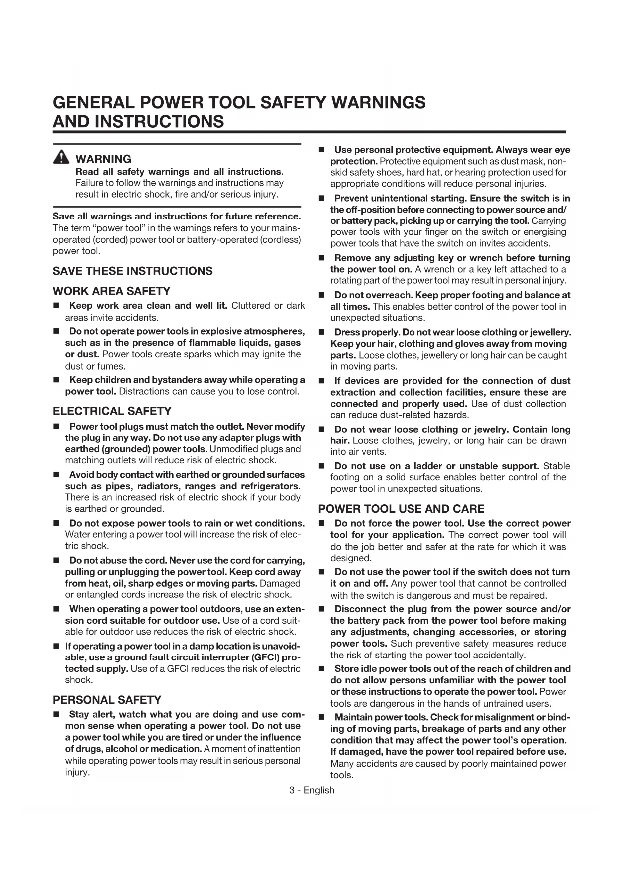
KNOW YOUR COLLATED SCREWDRIVER
See Figure 1, page 14.
The safe use of this product requires an understanding of the information on the product and in this operator's manual as well as a knowledge of the project you are attempting. Before use of this product, familiarize yourself with all operating features and safety rules.
ADJUSTABLE NOSEPIECES
Your screwdriver has adjustable nosepieces for varying screw depth. There are two nosepieces included, one for wood and one for drywall.
BELT CLIP
The reversible belt clip can be installed on either side of the screwdriver.
BIT LOAD BUTTON
The bit load button makes it quick and easy to change bits without the use of tools.
DEPTH OF DRIVE ADJUSTMENT
The drive depth can be adjusted for different applications and workpiece thickness using the depth of drive adjustment thumbwheel.
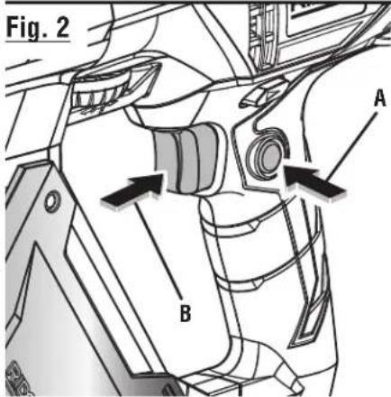
FORWARD/REVERSE SWITCH
The forward/reverse switch changes the direction of screw rotation.
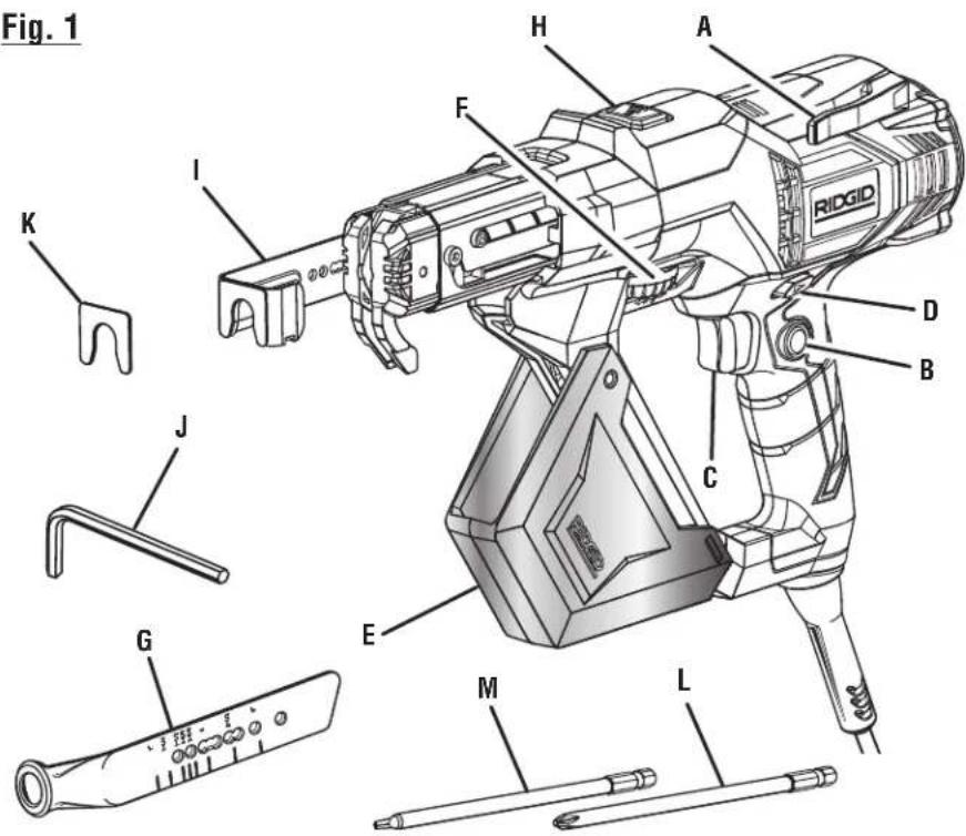
LOCK-ON BUTTON
The lock-on button is convenient for continuous use for extended periods of time.
ASSEMBLY
UNPACKING
This product has been shipped completely assembled.
- Carefully remove the product and any accessories from the box. Make sure that all items listed in the packing list are included.

WARNING:
Do not use this product if it is not completely assembled or if any parts appear to be missing or damaged. Use of a product that is not properly and completely assembled could result in serious personal injury.
■ Inspect the product carefully to make sure no breakage or damage occurred during shipping.
■ Do not discard the packing material until you have carefully inspected and satisfactorily operated the product.
■ If any parts are damaged or missing, please call 1-866-539-1710 for assistance.
PACKING LIST
Screwdriver
Adjustable Nosepiece (Wood)
Adjustable Nosepiece (Drywall)
Phillips Bit
Square Bit
Hex Key
Nosepiece Pads (2)
Tool Bag
Operator's Manual

WARNING:
If any parts are damaged or missing do not operate this product until the parts are replaced. Use of this product with damaged or missing parts could result in serious personal injury.

WARNING:
Do not attempt to modify this product or create accessories not recommended for use with this product. Any such alteration or modification is misuse and could result in a hazardous condition leading to possible serious personal injury.

WARNING:
Do not connect to power supply until assembly is complete. Failure to comply could result in accidental starting and possible serious personal injury.
OPERATION

WARNING:
Do not allow familiarity with products to make you careless. Remember that a careless fraction of a second is sufficient to inflict severe injury.

WARNING:
Always wear eye protection with side shields marked to comply with ANSI Z87.1. Failure to do so could result in objects being thrown into your eyes resulting in possible serious injury.
APPLICATIONS
You may use this product for the purposes listed below:
- Driving multiple screws into wood and drywall with screw-driver bits.
To turn the screwdriver ON, depress the switch trigger. Release the switch trigger to turn the screwdriver OFF.
LOCK-ON BUTTON
See Figure 2, page 14.
The screwdriver is equipped with a lock-on feature which is convenient for continuous driving of screws for extended periods of time. To lock-on, depress the switch trigger, push in and hold the lock-on button located on the side of the handle, then release switch trigger. Release the lock-on button and the screwdriver will continue running.
To release the lock, depress the switch trigger and release.
NOTE: If you have the lock-on feature engaged during use and the screwdriver becomes disconnected from the power supply, disengage the lock-on feature immediately.
FORWARD/REVERSE SWITCH
See Figure 3, page 14.
The direction of rotation of the bit is controlled by a switch located above the switch trigger. With the screwdriver held in normal operating position, the forward/reverse switch should be positioned to the left for forward driving operation. The direction of rotation is in reverse when the switch is to the right.
INSTALLING BITS
See Figure 4, page 14.
■ Unplug the screwdriver.
■ Remove screw strip from the tool if previously loaded.
- Hold the screwdriver upright and depress the bit load button.
■ Drop the bit into the feed housing.
■ While still holding the bit load button, depress the nose-piece with the palm of your opposite hand to center the bit.
■ Cycle the nosepiece up and down while gently shaking the tool until the bit drops into place.
NOTE: You should not be able to see the bit above the feed housing.
■ Release the button when the bit drops into place.
■ Make sure that the bit is secure by pointing the tool downward and shaking the tool.
■ If the bit is not secure, repeat the installation steps.
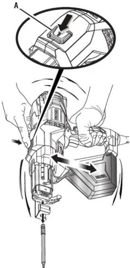
REMOVING BITS
See Figure 5, page 14.
■ Unplug the screwdriver.
■ Remove screw strip from tool if previously loaded.
■ Hold the tool with the nose pointed downward.
■ Depress the bit load button and shake the tool.
■ Release the button when the bit drops out of the feed housing.
SETTING SCREW LENGTH
See Figure 6, page 15.
The adjustable nosepiece allows the tool to automatically drive screws to preset depths.
To make preset depth adjustments:
■ Unplug the screwdriver.
■ Remove the nosepiece screw by turning counterclockwise.
NOTE: You may use the supplied hex key to loosen and tighten screw if desired.
■ Slide nosepiece into the slot along the side of the feed housing.
■ Align marks on the adjustable nosepiece with edge of feed housing for proper screw length.
■ Reinsert and tighten the nosepiece screw by turning in clockwise direction.
■ Make sure the nosepiece is securely attached before operating.
CHANGING THE NOSEPIECE
See Figure 6, page 15.
Two nosepieces are included, one for wood and one for drywall. The nosepiece can be removed and changed out by following the instructions in Setting Screw Length.
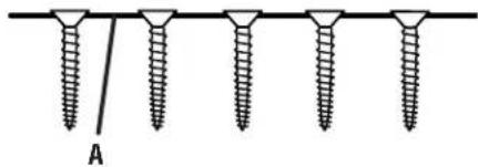
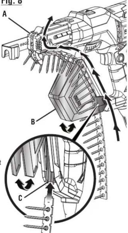
LOADING COLLATED SCREWS
See Figures 7 - 8, page 15.
Before loading the screwdriver, check to be sure tops of screws are resting on top of collated tape material as shown in figure 7.
To load screw strip:
■ Unplug the screwdriver.
■ Adjust nosepiece to correct screw length. Follow the instructions in Setting Screw Length.
■ Unsnap and rotate bottom of screw guard to access screw strip guide.
■ Feed screw strip into the strip guide.
■ Move the screw strip forward into the feed housing until the second empty hole lines up with the bit. This will allow the screws to advance properly when the nosepiece is depressed.
■ Snap the screw guard back in place.
To remove screw strip:
■ Unplug the screwdriver.
■ Pull screw strip through from the top of the feed housing.
DEPTH OF DRIVE ADJUSTMENT
See Figure 9, page 15.
The depth of drive adjustment thumbwheel allows fine tuning of the countersink. Begin each new job by driving several test screws in scrap material to check and adjust for proper countersink.
The screwdriver has a depth-sensing clutch. When the screw is countersunk to the preset depth, it automatically disengages and makes a clicking or racheting sound. This is normal and signals completion of the drive.
DRIVING SCREWS
See Figure 10, page 15.
- Check the adjustable nosepiece for proper screw length setting.
- Check the direction of rotation selector for correct setting (forward or reverse).
- Secure the workpiece. Use clamps if necessary.
- Plug the screwdriver into power supply source.
- Hold the screwdriver firmly. For best results, keep the screwdriver at a right angle to the work surface.
■ Depress the switch trigger to start the screwdriver. Press the nosepiece, with constant force, against the work surface. Do not remove the tool from the work surface until the clutch disengages and the bit stops rotating, signaling a fully driven screw. - Check for proper countersink. Adjust using depth of drive adjustment thumbwheel if necessary.
■ You may keep the switch trigger depressed so the next screw will be automatically fed into place when the tool is depressed against the work surface.

WARNING:
When servicing use only identical RIDGID® replacement parts. Use of any other parts could create a hazard or cause product damage.

WARNING:
Always wear eye protection with side shields marked to comply with ANSI Z87.1. Failure to do so could result in objects being thrown into your eyes resulting in possible serious injury.
GENERAL MAINTENANCE
Avoid using solvents when cleaning plastic parts. Most plastics are susceptible to damage from various types of commercial solvents and may be damaged by their use. Use clean cloths to remove dirt, dust, oil, grease, etc.

WARNING:
Do not at any time let brake fluids, gasoline, petroleum-based products, penetrating oils, etc., come in contact with plastic parts. Chemicals can damage, weaken or destroy plastic which could result in serious personal injury.
Electric tools used on fiberglass material, wallboard, spackling compounds, or plaster are subject to accelerated wear and possible premature failure because the fiberglass chips and grindings are highly abrasive to bearings, brushes, commutators, etc. Consequently, we do not recommend using this product for extended work on these types of materials. However, if you do work with any of these materials, it is extremely important to clean the product using compressed air.
LUBRICATION
All of the bearings in this product are lubricated with a sufficient amount of high grade lubricant for the life of the unit under normal operating conditions. Therefore, no further lubrication is required.
POWER SUPPLY CORD REPLACEMENT
If replacement of the power supply cord is necessary, this must be done by an authorized service center in order to avoid a safety hazard.
REPLACING THE NOSEPIECE PAD
The pad on the end of the nosepiece for wood will wear with continued use. To replace the nosepiece:
Unplug the screwdriver. Remove the existing pad and clean the nosepiece to remove all residue. Remove the adhesive backing from a new pad and firmly press to secure.
ACCESSORIES
Look for these accessories where you purchased this product:
Phillips Bit....AC96601
■ Square Bit....AC96602

WARNING:
Current attachments and accessories available for use with this tool are listed above. Do not use any attachments or accessories not recommended by the manufacturer of this tool. The use of attachments or accessories not recommended can result in serious personal injury.
NOTE: FIGURES (ILLUSTRATIONS) START ON PAGE 14 AFTER FRENCH AND SPANISH LANGUAGE SECTIONS.
| PROBLEM CAUSE SOLUTION | ||
| Motor starts slowly or fails to come to full speed. | Starting switch not operating. Have switch replaced. | |
| Voltage too low to permit motor to reach operating speed. | Request voltage check from the power company. | |
| Fuses or circuit breakers do not have sufficient capacity. | Install proper size fuses or circuit breakers. | |
| Tool does not drive screw into material. | Bit is worn. Replace the bit. | |
| Overloaded motor. Check applications section for proper uses. | ||
| Tool does not complete drive. Depth of drive improperly set. Adjust depth of drive. | ||
| Screws do not advance. Screw length not set correctly. Adjust according to Setting Screw Length section. | ||
| Screws fall out during application. | Screw length not set correctly. | Adjust according to Setting Screw Length section. |
| Bit track is damaged or worn. Replace slide body assembly. | ||
| Bit does not install correctly. Bit not properly seated into bit housing. | Refer to Installing Bits section. | |
| Bit slides or jumps off screw. Screw is driven at an angle. | Tool is pushed forward during drive. Hold tool firmly while working. | |
| Tool is out of alignment. | Return to authorized service center. | |
| Bit track is damaged or worn. Replace slide body assembly. | ||
| Screw jams. | Screw length not set properly. | Adjust according to Setting Screw Length section. |
| Nosepiece screw loosened. | Tighten nosepiece screw. | |
| Bit track is damaged or worn. Replace slide body assembly. | ||
| Bit is damaged or worn. | Replace bit. | |
| Nosepiece is bent or damaged. | Replace nosepiece. | |
| Slide mechanism sticks or “returns” slowly. | Build up of debris in mechanism. | Clean return mechanism. |
| Weak return spring. | Replace spring. | |
| Motor overheats. | Overloaded motor. Check applications section for proper uses. | |
| Pushing force becomes difficult. | Slide body assembly is worn. | Replace slide body assembly. |
RIDGID® HAND HELD AND STATIONARY POWER TOOL 3 YEAR LIMITED SERVICE WARRANTY
Proof of purchase must be presented when requesting warranty service.
Limited to RIDGID® hand held and stationary power tools purchased 2/1/04 and after. This product is manufactured by One World Technologies, Inc. The trademark is licensed from RIDGID, Inc. All warranty communications should be directed to One World Technologies, Inc., attn: RIDGID Hand Held and Stationary Power Tool Technical Service at (toll free) 1-866-539-1710.
90-DAY SATISFACTION GUARANTEE POLICY
During the first 90 days after the date of purchase, if you are dissatisfied with the performance of this RIDGID® Hand Held and Stationary Power Tool for any reason you may return the tool to the dealer from which it was purchased for a full refund or exchange. To receive a replacement tool you must present proof of purchase and return all original equipment packaged with the original product. The replacement tool will be covered by the limited warranty for the balance of the 3 YEAR service warranty period.
WHAT IS COVERED UNDER THE 3 YEAR LIMITED SERVICE WARRANTY
This warranty on RIDGID® Hand Held and Stationary Power Tools covers all defects in workmanship or materials and normal wear items such as brushes, chucks, motors, switches, cords, gears and even cordless batteries in this RIDGID® tool for three years following the purchase date of the tool. Warranties for other RIDGID® products may vary.
HOW TO OBTAIN SERVICE
To obtain service for this RIDGID® tool you must return it; freight prepaid, or take it in to an authorized service center for RIDGID® branded hand held and stationary power tools. You may obtain the location of the authorized service center nearest you by calling (toll free) 1-866-539-1710 or by logging on to the RIDGID® website at www.ridgid.com. When requesting warranty service, you must present the original dated sales receipt. The authorized service center will repair any faulty workmanship, and either repair or replace any part covered under the warranty, at our option, at no charge to you.
WHAT IS NOT COVERED
This warranty applies only to the original purchaser at retail and may not be transferred. This warranty only covers defects arising under normal usage and does not cover any malfunction, failure or defect resulting from misuse, abuse, neglect, alteration, modification or repair by other than an authorized service center for RIDGID® branded hand held and stationary power tools. Consumable accessories provided with the tool such as, but not limited to, blades, bits and sand paper are not covered.
RIDGID, INC. AND ONE WORLD TECHNOLOGIES, INC. MAKE NO WARRANTIES, REPRESENTATIONS OR PROMISES AS TO THE QUALITY OR PERFORMANCE OF ITS POWER TOOLS OTHER THAN THOSE SPECIFICALLY STATED IN THIS WARRANTY.
ADDITIONAL LIMITATIONS
To the extent permitted by applicable law, all implied warranties, including warranties of MERCHANTABILITY or FITNESS FOR A PARTICULAR PURPOSE, are disclaimed. Any implied warranties, including warranties of merchantability or fitness for a particular purpose, that cannot be disclaimed under state law are limited to three years from the date of purchase. One World Technologies, Inc. and RIDGID, Inc. are not responsible for direct, indirect, incidental or consequential damages. Some states do not allow limitations on how long an implied warranty lasts and/or do not allow the exclusion or limitation of incidental or consequential damages, so the above limitations may not apply to you. This warranty gives you specific legal rights, and you may also have other rights which vary from state to state.
One World Technologies, Inc.
P.O. Box 35, Hwy. 8
Pickens, SC 29671
A subsidiary of Techtronic Industries Co., Ltd.
OTC: TTNDY
AVERTISSEMENTS GÉNÉRAUX ET INSTRUCTIONS GÉNÉRALES DE SÉCURITÉ EN CE QUI A TRAIT AUX OUTILS ÉLECTRIQUES

AVERTISSEMENT
Some examples of these chemicals are:
INSTALLATION DES EMBOUTS
Voir la figure 4, page 14.
REEMPLACEMENT DU CORDON D'ALIMENTATION
REPLACEMENT DU COUSSINET POUR BOUT
PROBLÈME CAUSE POSSIBLE SOLUTION
RÉPARATIONS SOUS GARANTIE
One World Technologies, Inc.
P.O. Box 35, Hwy. 8
Pickens, SC 29671, ÉTATS-UNIS
Une filiale de Techtronic Industries Co., Ltd.
OTC : TTNDY
One World Technologies, Inc.
P.O. Box 35, Hwy. 8
Pickens, SC 29671, USA
Una subsidiaria de Techtronic Industries Co., Ltd.
OTC : TTNDY
A - Reversible belt clip (crochet de ceinture réversible, clip para el cinto reversible)
B - Lock-on button (bouton de verrouillage, botón de seguro de encendido)
C - Switch trigger (gâchette, gatillo del interruptor)
D - Forward reverse switch (interrupteur « marche avant/marche arrière », selector de marcha adelante/atrás)
E - Screw guard (garde vis, protección para tornillos)
F - Depth of drive adjustment thumbwheel (molette de réglage de la profondeur de vissage, ruedecilla para el ajuste de la profundidad de introducción)
G - Adjustable nosepiece (drywall) [bout réglable (cloison sèche), punta ajustable (paneles de yeso)]
H - Bit load button (bouton de charger de l'embout, botón del carga de las puntas)
I - Adjustable nosepiece (wood) [bout réglable (bois), punta ajustable (madera)]
J - Hex key (clé hexagonale, llave hexagonal)
K - Nosepiece pad (wood) [coussinets pour bout (bois), almohadillas para puntas (madera)]
L - Phillips bit (embout phillips, puntas tipo Phillips)
M - Square bit (embout carrée, punta cuadrada)
A - Lock-on button (bouton de verrouillage, botón de seguro de encendido)
B - Switch trigger (gâchette, gatillo del interruptor)
A - Adjustable nosepiece (wood) [bout réglable (bois), punta ajustable (madera)]
B - Feed housing (logement d'alimentation
eur compartimiento de alimentación)
C - Bit load button (bouton de charger de l'embout, botón del carga de las puntas)
Fig. 5
A - Bit load button (bouton de charger de l'embout, botón del carga de las puntas)
Fig. 6
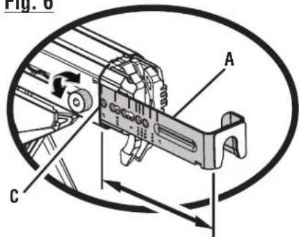
A -Adjustable nosepiece (wood) [bout réglable (bois), punta ajustable (madera)]
B - Nosepiece screw (vis d'arrimage du bout, tornillo de la punta)
C - Feed housing edge (rebord du logement d'alimention, borde del compartimiento de alimentación)
D - Adjustable nosepiece (drywall) [bout réglable (cloison sèche), punta ajustable (paneles de yeso)]
Fig. 7
CORRECT
(CORRECT, CORRECTO)
INCORRECT
(INCORRECT, INCORRECTO)
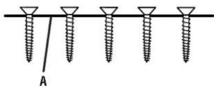
A - Collated tape (bande, cinta de la tira)
Fig. 8
COLLATED SCREWDRIVER
DOUBLE INSULATED
MANUEL D'UTILISATION
TOURNEVIS A CHARGEUR DE VIS EN BANDE
DOUBLE ISOLATION
MANUAL DEL OPERADOR
Customer Service Information:
For parts or service, contact your nearest RIDGID® authorized service center. Be sure to provide all relevant information when you call or visit. For the location of the authorized service center nearest you, please call 1-866-539-1710 or visit us online at www.ridgid.com.
The model number of this tool is found on a plate attached to the motor housing. Please record the serial number in the space provided below. When ordering repair parts, always give the following information:
Model No. R6791
Serial No. ____


- COLLATED SCREWDRIVER
- WARNING
- SAVE THIS MANUAL FOR FUTURE REFERENCE
- SAVE THESE INSTRUCTIONS
- WORK AREA SAFETY
- ELECTRICAL SAFETY
- PERSONAL SAFETY
- POWER TOOL USE AND CARE
- GENERAL POWER TOOL SAFETY WARNINGS AND INSTRUCTIONS
- SERVICE
- SCREWDRIVER SAFETY WARNINGS AND INSTRUCTIONS
- CALIFORNIA PROPOSITION 65
- DOUBLE INSULATION
- ELECTRICAL CONNECTION
- EXTENSION CORDS
- PRODUCT SPECIFICATIONS
- KNOW YOUR COLLATED SCREWDRIVER
- SEE FIGURE 1, PAGE 14
- ADJUSTABLE NOSEPIECES
- BELT CLIP
- BIT LOAD BUTTON
- DEPTH OF DRIVE ADJUSTMENT
- FORWARD/REVERSE SWITCH
- LOCK-ON BUTTON
- ASSEMBLY
- UNPACKING
- PACKING LIST
- OPERATION
- APPLICATIONS
- INSTALLING BITS
- REMOVING BITS
- SETTING SCREW LENGTH
- TO MAKE PRESET DEPTH ADJUSTMENTS
- CHANGING THE NOSEPIECE
- LOADING COLLATED SCREWS
- TO LOAD SCREW STRIP
- TO REMOVE SCREW STRIP
- DRIVING SCREWS
- GENERAL MAINTENANCE
- LUBRICATION
- POWER SUPPLY CORD REPLACEMENT
- REPLACING THE NOSEPIECE PAD
- ACCESSORIES
- NOTE: FIGURES (ILLUSTRATIONS) START ON PAGE 14 AFTER FRENCH AND SPANISH LANGUAGE SECTIONS
- RIDGID® HAND HELD AND STATIONARY POWER TOOL 3 YEAR LIMITED SERVICE WARRANTY
- 90-DAY SATISFACTION GUARANTEE POLICY
- WHAT IS COVERED UNDER THE 3 YEAR LIMITED SERVICE WARRANTY
- HOW TO OBTAIN SERVICE
- WHAT IS NOT COVERED
- ADDITIONAL LIMITATIONS
- AVERTISSEMENTS GÉNÉRAUX ET INSTRUCTIONS GÉNÉRALES DE SÉCURITÉ EN CE QUI A TRAIT AUX OUTILS ÉLECTRIQUES
- AVERTISSEMENT
- INSTALLATION DES EMBOUTS
- REEMPLACEMENT DU CORDON D'ALIMENTATION
- REPLACEMENT DU COUSSINET POUR BOUT
- RÉPARATIONS SOUS GARANTIE
- MANUEL D'UTILISATION
- TOURNEVIS A CHARGEUR DE VIS EN BANDE
- MANUAL DEL OPERADOR
- CUSTOMER SERVICE INFORMATION
Brand : RIDGID
Model : R6791
Category : Screwdriver