61-337 - Multimeter IDEAL - Free user manual and instructions
Find the device manual for free 61-337 IDEAL in PDF.

| Product Type | TRMS Digital Multimeter |
| Brand | IDEAL |
| Model | 61-337 |
| Dimensions (L x W x H) | 167 mm x 82 mm x 39 mm |
| Weight | 0.306 kg (0.675 lb) |
| Power Supply | 3 AAA 1.5 V batteries |
| Display | LCD 4000 counts |
| Measurement Functions | AC/DC TRMS voltage, AC/DC current, resistance, capacitance, frequency, duty cycle, temperature (type K), continuity, diode, non-contact voltage detection (NCV) |
| Voltage Ranges | 400 mV to 600 V (AC/DC) |
| Current Ranges | 400 µA to 10 A (AC/DC) |
| Resistance Ranges | 400 Ω to 40 MΩ |
| Capacitance | 400 nF to 4000 µF |
| Frequency | 9.999 Hz to 9.999 kHz |
| Temperature | -40 °C to 1000 °C (-40 °F to 1832 °F) |
| Continuity | Threshold < 10 Ω with audible tone and red LED |
| Diode Test | Typical forward voltage 0.5 to 0.8 V |
| NCV | Voltage detection 40-600 V AC, 50-60 Hz |
| Safety | CAT IV 600 V, CAT III 1000 V, dual insulation |
| Protection Fuses | 400 mA/600 V (6x32 mm) and 10 A/600 V (10x38 mm) |
| Auto Power Off | After 30 minutes of inactivity, disableable |
| Lighting | White backlight, auto off after 5 min |
| Warranty | 2 years |
| Care and Cleaning | Clean with a damp cloth and mild detergent; do not use abrasive products |
| Spare Parts and Repairability | Batteries (AAA), specified fuses, type K thermocouple; repair by qualified personnel |
Frequently Asked Questions - 61-337 IDEAL
User questions about 61-337 IDEAL
0 question about this device. Answer the ones you know or ask your own.
Ask a new question about this device
Download the instructions for your Multimeter in PDF format for free! Find your manual 61-337 - IDEAL and take your electronic device back in hand. On this page are published all the documents necessary for the use of your device. 61-337 by IDEAL.
USER MANUAL 61-337 IDEAL
IDEAL® Test and Measurement
61-337 Multimeter Operation and Safety Manual
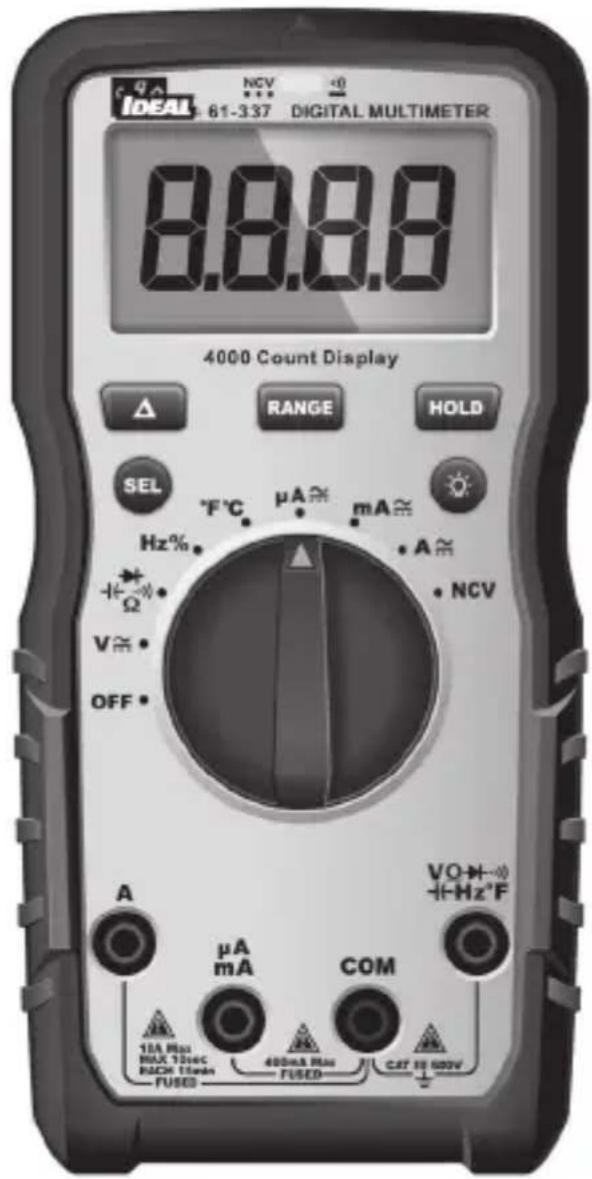
Table of Contents
Introduction....3
Contacting IDEAL INDUSTRIES, INC ....3
Safety Information 4
Warnings 4-5
Cautions 5
Symbols 6-7
Operation....8-25
Identification and description of operating controls and functions 8-9
Operating Features....10-11
Using Test Leads....12
Meter Operation 13-19
Non-Contact Voltage Testing 13
Lead Warning....14
Fuse Warning....14
SEL Button....14
Measuring Voltage....15
Measuring Continuity 16
Measuring Resistance....16
Measuring Capacitance 17
Measuring Diodes 17
Measuring Frequency 18
Measuring Temperature 18
Measuring Micro Amps 19
Measuring Milli Amps 19
Measuring Amps 19
Functions Operation Table....20-21
Functions Indication Table 22-23
Electrical Specifications 24-25
Environmental Specifications....26
Mechanical Specifications 26
EMC / EMI 26
FCC 27
Safety 27
Maintenance and Service 27-28
Introduction
The IDEAL ^® 61-337 Digital Multimeter is an auto ranging average responding RMS meter that measures AC and DC current (amps) in series via test leads in the designated terminals, measures voltage, frequency, resistance, continuity, capacitance, diodes via test-leads in the designated terminal and measures temperature via a K-Type thermocouple. It also detects the presence of voltage between 40V to 600V AC via a non-contact sensor in the top center of the meter.


Arc Flash and Shock Hazard, Proper PPE Required. Follow all safety procedures, wear proper PPE in accordance to NFPA 70E. Read and fully understand the instruction manual prior to using this product. Failure to comply can result in serious injury or death.
Contacting IDEAL INDUSTRIES, INC.
To contact IDEAL INDUSTRIES, INC., call one of the following telephone numbers:
IDEAL Industries USA Customer Service
• Phone Number: 800-435-0705
- Email: contactus@idealindustries.com
IDEAL Industries Canada Customer Service
• Phone Number: 905-683-3400
- Email: ideal_Canada@idealindustries.com
IDEAL Industries EMEA
• Phone Number: +44 (0)1925 444 446
- Email: eur.sales@idealindustries.com
IDEAL Industries Australia
• Phone Number: +61 3 9562 0175
- Email: InfoAUS@idealindustries.com
Or visit the IDEAL Electrical Website at www.idealind.com
To register your product, find manuals, watch videos, simply scan this QR code.


Safety Information
Warning - Identifies conditions and actions that could result in or serious injury if the hazard is realized.

Caution - Identifies conditions and actions that could result in meter dam- , equipment under test damage or data loss if the hazard is realized.
WARNING
Arc Flash and Shock Hazard, Proper PPE Required. Follow all safety procedures, wear proper PPE in accordance to NFPA 70E and follow the guidelines below and the instructions in this manual when operating the meter. Failure to comply can result in serious injury or death.
- Choking Hazard, Small Parts. Keep Away from Children. Sharp Objects Hazard, This is not a toy. It is not for use or play by children. Keep Away from Children. Failure to do so can result in serious injury.
- Only experienced or technically competent consumers should use this equipment. When in doubt, call an experienced electrician to make any and all necessary repairs or installations. At all times, perform any necessary work on a de-energized circuit that has had its circuit breaker turned off and has been locked out.
- Use the Meter only as specified in this manual or protection provided by the Meter can be compromised.
- Before using or connecting the Meter, visually inspect it to ensure the cases are not cracked and the back case is securely in place. Do not use if the Meter appears damaged.
- Before using the test leads, inspect carefully for damaged insulation, exposed metal or cracked probes. Check test leads for continuity. Do not use leads if they appear damaged.
- Use only approved test leads. Do not use improvised connections that could present a safety hazard.
- When using the probes, keep fingers behind the guard ring on the probes.
- Connect the common test lead before connecting the live test lead. When disconnecting test leads, disconnect the live test lead first.
- This Meter is intended for use by qualified electricians. Follow NFPA 70E Standards for Electrical Safety in the Workplace when using this Meter.
- Do not use without the batteries correctly in place and the battery door closed and secured.
- Do not use Meter if it operates incorrectly as protection may be compromised. When in doubt, have the Meter serviced.
- When servicing the Meter, use only specified replacement parts.
Arc Flash and Shock Hazard, Proper PPE Required. Follow all safety procedures, wear proper PPE in accordance to NFPA 70E and follow the guidelines below and the instructions in this manual when operating the meter. Failure to comply can result in serious injury or death.
- Have the Meter serviced only by qualified service personnel.
- Do not use the Meter around explosive gas, dust, or vapor, or during electrical storms, or in wet environments.
- When measuring, keep fingers behind the Tactile Barrier. See "The Meter" on pg. 8 and 9.
- Do not apply more than the rated voltage, as marked on the Meter, between the terminals or between any terminal and earth ground.
- To avoid false readings that can lead to electrical shock and injury, replace the batteries as soon as the low battery indicator (☐) appears.
- Remove the test leads from the circuit prior to removing the battery door.
- Voltages exceeding 30VAC or 60VDC pose a shock hazard so use caution.
- Always ensure that test leads are secured so that they cannot be accidentally snagged or tripped over.
- Do not work alone so that assistance can be rendered in an emergency.
- Use extreme caution when working around bare conductors or bus bars. Contact with the conductor could result in electric shock.
- Adhere to local and national safety codes. Individual protective equipment must be used to prevent shock and arc blast injury where hazardous live conductors are exposed.
- Disconnect circuit power and discharge all high-voltage capacitors before you measure resistance, continuity, or capacitance.
- Never operate the Meter with the back cover removed or the case open.
• Cancer and Reproductive Harm - www.P65Warnings.ca.gov

CAUTION
Meter damage, equipment under test damage or data loss can occur if the following guidelines are not adhered to.
- Use the proper terminals, function, and range for the measurement application.
- Clean the case and accessories with a damp cloth and mild detergents only. Do not use abrasives or solvents. Make sure the meter is completely dry before use.
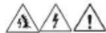
Symbols & Descriptions
| SYMBOL DESCRIPTION | |
 | Arc Flash and Shock Hazard |
 | Shock Hazard |
 | Warning or Caution |
 | Choking Hazard |
 | AC (Alternating Current) |
 | DC (Direct Current) |
 | Low Battery Indicator |
 | Earth Ground |
| 10 A Max | mum Current Specification |
| CAT III | IEC Measurement Category IIICAT III has protection against transients in equipment in fixed-equipment installations such as distribution panels feeders, and short branch circuits. Also included are lighting systems in larger buildings. |
| NCV | Non-Contact Voltage Sensing |
 | Non-Contact Voltage Sensing Point |
| A | Amperage AC and DC |
| Hz | Frequency measured via the test leads |
| V | Voltage AC or DC |
Hz% | Frequency displayed as % measured with AC VoltageOhms |
 | Continuity |
 | Capacitance |
 | Diode |
| [H0WA] Temperature Degrees Fahrenheit / Celsius | |
 Liquid Crystal Display Liquid Crystal Display | |
| [4K3A] Auto or Manual Range Selection | |
 | Delta (Relative) |
 | Double Insulation |
 | Do not dispose of this product as unsorted municipal waste. It must be properly disposed of in accordance with local regulations. Please see www.epa.gov or www.erecycle.org for additional information. |
 | Conforms to applicable North American Safety Standards |
 | Conforms to applicable Australian Safety Standards |
 | Conforms to European Directives |
NOTE: The Measurement Category (CAT) and voltage rating of any combination of test probe, test probe accessory, current clamp accessory, and the Meter is the LOWEST rating of any individual component.
Operation
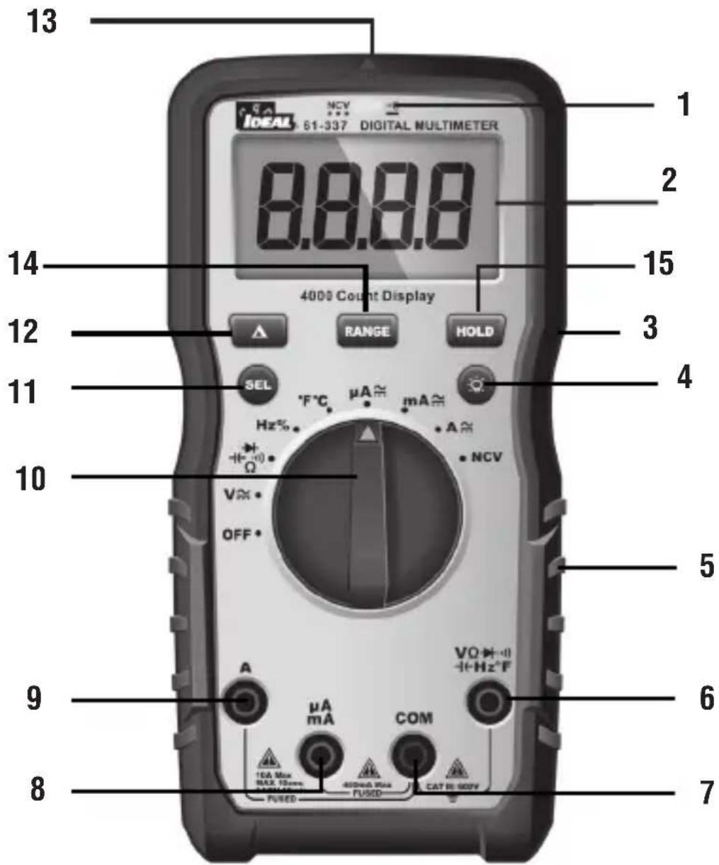
Identification and Description of Operating Controls and Functions for the 61-337 Digital Multimeter:
- HV, & Continuity LED
- LCD Display
- Tactile Barrier
- Backlight Button
- Rubber Boot
- Volts/Ohms Input Terminal
- Common (COM) Input Terminal
- Mili Amps, Micro Amps Input Terminal
- Amps Input Terminal
- Measuring Functions Dial
- Function Select Button
- Relative Button
- NCV Sensing Point
- Range
- Hold
Operating Features
High Voltage Warning (HI-V)
The meter beeps once (for 1 second) and a red LED illuminates and remains on as long as the voltage remains above 30V AC or DC, or when the meter's voltage range is exceeded.
NOTE: This feature does not work in the Ohm, capacitor, continuity or amperage modes.
Data Hold Feature
Press the Hold button to toggle in and out of the data hold mode. "H" appears in the upper left of the meter display when data hold is active. Use the data hold feature to lock a measurement reading on the display. Press the Hold button again to unlock the display and obtain a real-time reading.
REL Feature (Δ)
A short press of the 'Δ' button will activate or deactivate the REL function.
Range
The meter is auto ranging, however the user may select a specific range by pressing the range button repeatedly.
Auto Power Off (APO) Feature Disable
The meter automatically powers itself down after about 30 minutes of no use. Press any button, and the meter will wake up and enter the default function of that setting before power down. To Disable APO, press and hold the SEL button while turning the dial to any desired function. When APO is defeated, the “APO” will be removed from the display. Turning the meter off and back on will restore the APO default.
Backlight
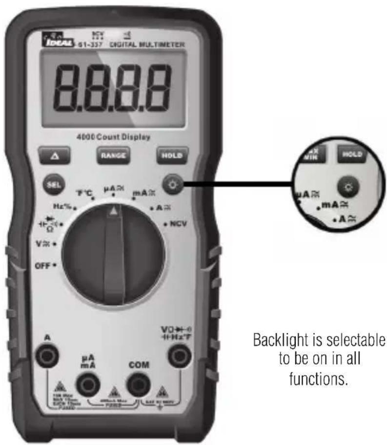
Backlight is selectable to be on in all functions.
Press the Backlight button on the meter to turn the backlight on and off. The white backlight will remain lit for about 5 minutes before it automatically turns off to conserve battery power. Or turn the backlight off by pressing the button again.
Using Test Leads
WARNING: Arc Flash and Shock Hazard, Proper PPE Required.
Follow all safety procedures, wear proper PPE in accordance to NFPA 70E and follow the guidelines below and the instructions in this manual when operating the meter with TL-757 Test Leads or equivalent. Test Leads must be rated for the electrical environment the meter is being used in and have a voltage rating of at least the voltage of the circuit to be measured. Failure to comply can result in serious injury or death.
• Choking Hazard, Small Parts. Keep Away from
Children. Sharp Objects Hazard, This is not a toy. It is not for use or play by children. Failure to do so can result in serious injury or death.
- Use only approved test leads. Do not use improvised connections that could present a safety hazard.
- Ensure that the test leads are inserted into the correct input jacks when measuring AC or DC current.
- Prior to using the test leads, inspect them carefully for damaged insulation, exposed metal or bent probes. Check test leads for continuity. Do not use leads if they appear damaged.
- When using the probes, keep fingers behind the guard rings on the probes.
- Connect the common test lead before connecting the live test lead. When disconnecting test leads, disconnect the live test lead first.
- Always ensure that test leads are secured so that they cannot be accidentally snagged or tripped over.
Protective Cap Guard Ring
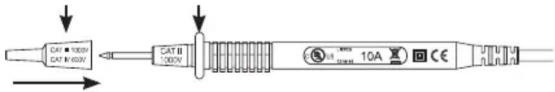
Note: The 61-337 is only rated to 600V AC or DC MAX.
WARNING: Arc Flash and Shock Hazard, Proper PPE Required.
Follow all safety procedures, wear proper PPE in accordance to NFPA 70E and assure that the Protective Caps are in place when operating a properly rated electrical meter/tester using the TL-757 Test Leads in a CAT IV 600V or CAT III 1000V environment.
This meter is intended for use with the IDEAL TL-757 lead set (provided with this product) or equivalent. The lead set must comply with requirements for Overvoltage and Measurement Categories CAT IV 600V CAT III 1000V.
This meter is CAT III 600V ONLY
Meter Operation
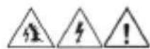
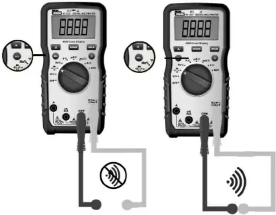
Non-Contact Voltage Sensing
First, rotate the function key to the NCV position. Place the sensing point marked with NCV close to an AC outlet (or any AC conductor such as light switches or power cords) and scan back and forth across the outlet. The meter beeps On/Off continuously and the Red NCV LED above the display flashes if the sensing antenna detects live voltage greater than 40V AC (50 -60 Hz). Voltages with frequencies higher than 60Hz or electrostatic charges may also be detected by the NCV sensing antenna. To differentiate between hot and neutral in an outlet, place the NCV tab directly next to each slot in the outlet. The tone (buzzer) will sound over the slot that is energized and not on the neutral slot. Either test lead can also be used to differentiate between the hot and neutral. Plug the red or black test lead into the V input jack on the meter. With the function switch in the NCV position, insert the probe end of just one probe into the slots on the outlet. The meter will beep and the Red LED will flash when a hot conductor is contacted.
NOTE: While the NCV is a helpful function, it is ALWAYS RECOMMENDED that the operator verify that any electrical conductor is completely de-energized and that no voltage is present by measuring for voltage AND CONFIRMING THAT NO VOLTAGE IS PRESENT and that all applicable PPE and lock out tag out procedures be followed before attempting any work on ANY electrical distribution system.
Lead Warning
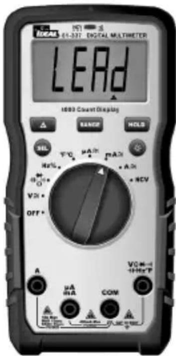
Lead Warning: When inserting the test lead into any amperage input terminal, but the rotary function switch IS NOT set to the correct relative amperage position, the meter will beep at 3Hz, LCD will display "LEAd" and " ", flashes at 3Hz. If any amperage function is selected first, but the test lead IS NOT in the relative amperage input jack, the meter will also beep at 3Hz and the LCD will display "LEAd" and " ", flashes at 3Hz.
Fuse Warning
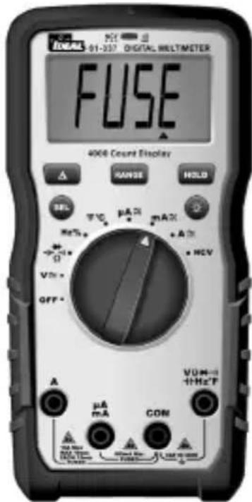
Fuse Notification: The test leads CANNOT be short circuited or used for measuring while testing the fuse.
- If the 400mA/600V fuse is blown, setting the rotary switch to the "mA" or "uA" setting, the LCD will display "FUSE" and " ", and the buzzer will beep continuously at the same time.
- If the 10A/600V fuse is blown, setting the rotary switch to the "A" setting, the LCD will display "FUSE" and " ", and the buzzer will beep continuously at the same time.
SEL Button
The SEL Button allows the user to toggle between multiple functions when the function dial is used to select a specific function. This can include but is not limited to toggling between degrees F and C, AC and DC voltage or current, continuity, resistance, capacitance and diode measurements.
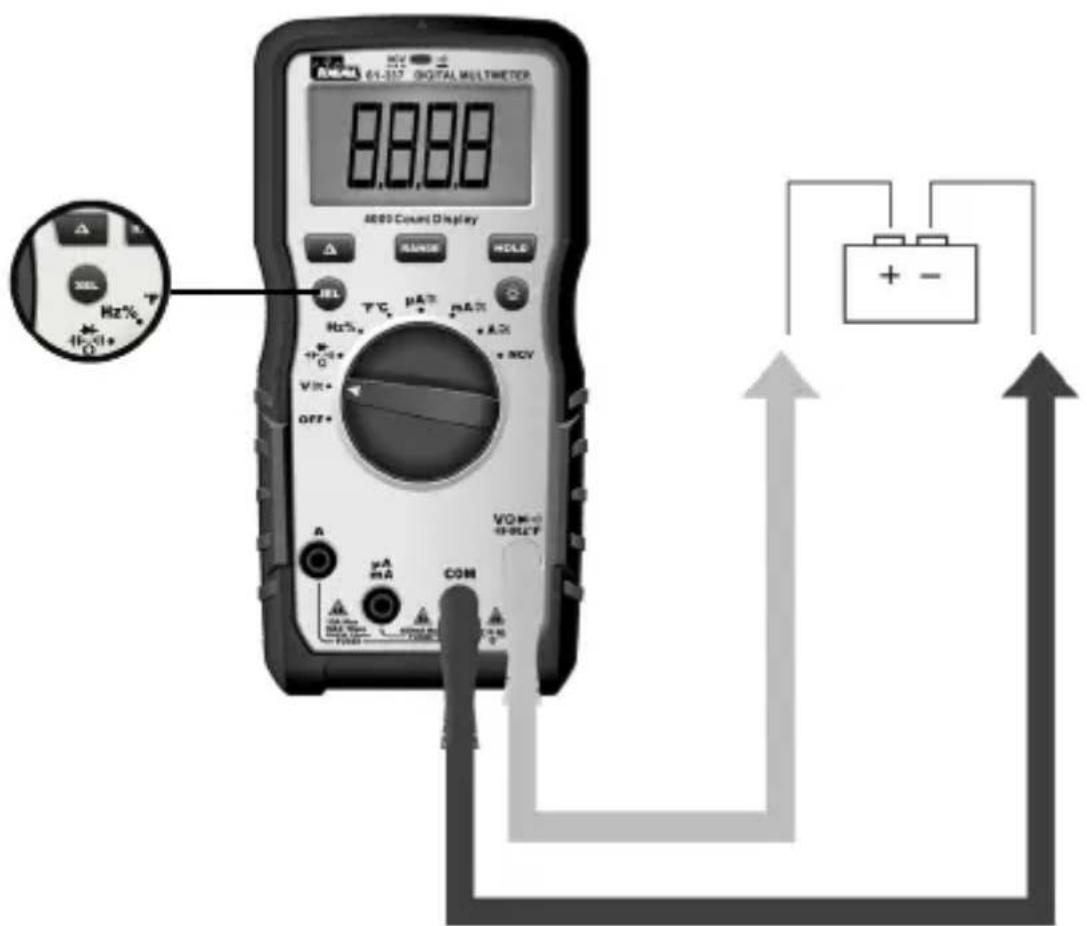
Measuring AC ( ) Voltage
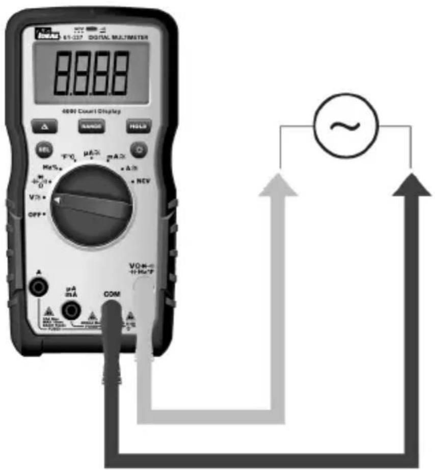
Measuring DC ( ·s ) Voltage
Verifying Continuity ( )
- Verify the circuit is de-energized.
- The meter will sense the level of resistance and beep if the resistance is less than 10 Ω's to confirm that continuity is present.
- The red LED will illuminate and the resistance value will be displayed.
- The default setting is Continuity
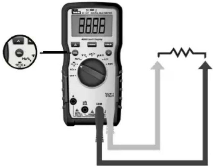
Measuring Resistance (Ohms / Ω)
- Verify the circuit is de-energized to obtain accurate measurements.
- To exit Continuity and enter the Resistance mode, press the SEL button.
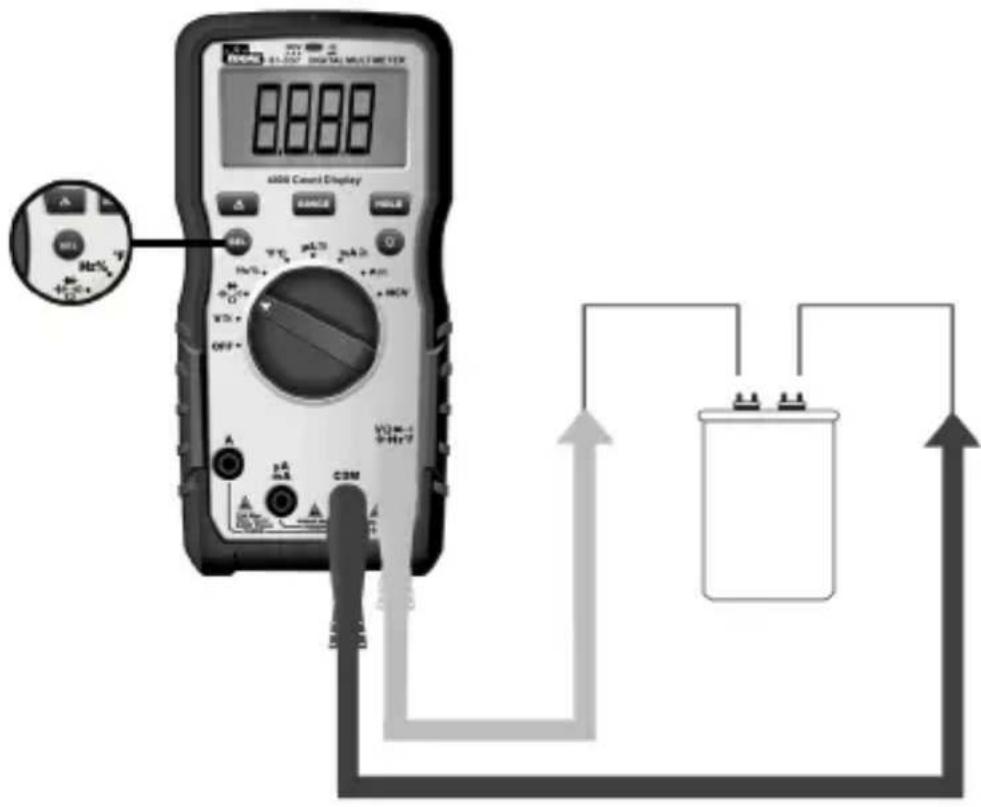
Measuring Capacitance ( - )
- To exit Resistance and enter the Capacitance mode, press the SEL button.
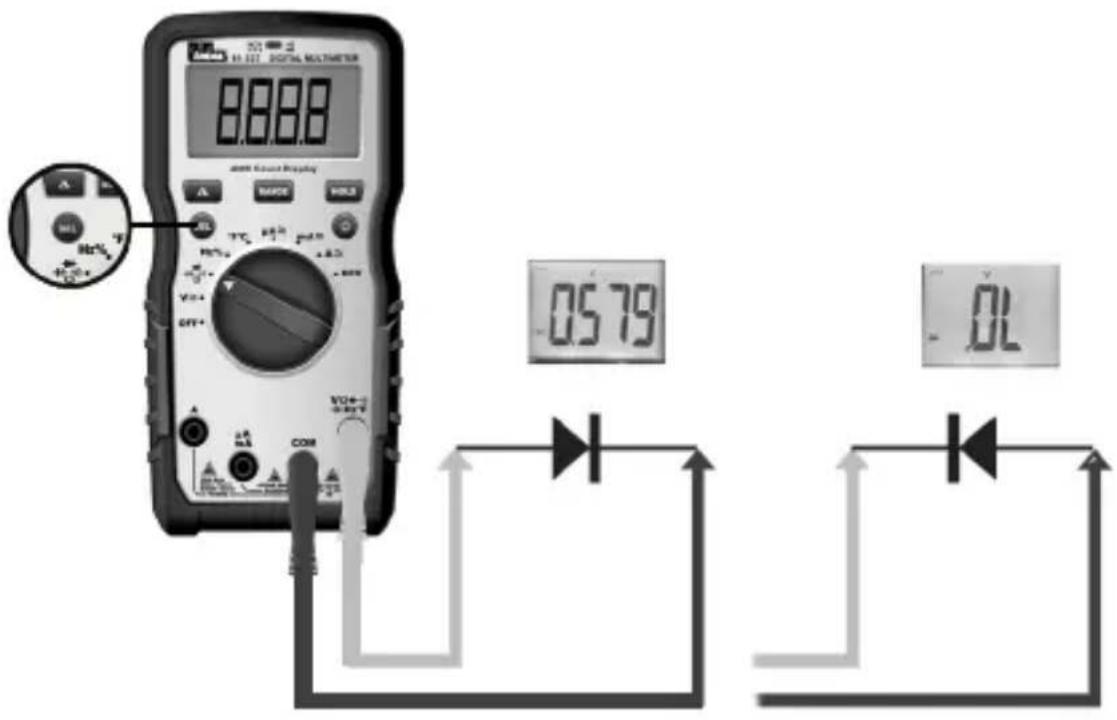
Measuring Diodes (→+)
- To exit Capacitance and enter the Diode Test mode, press the SEL button.
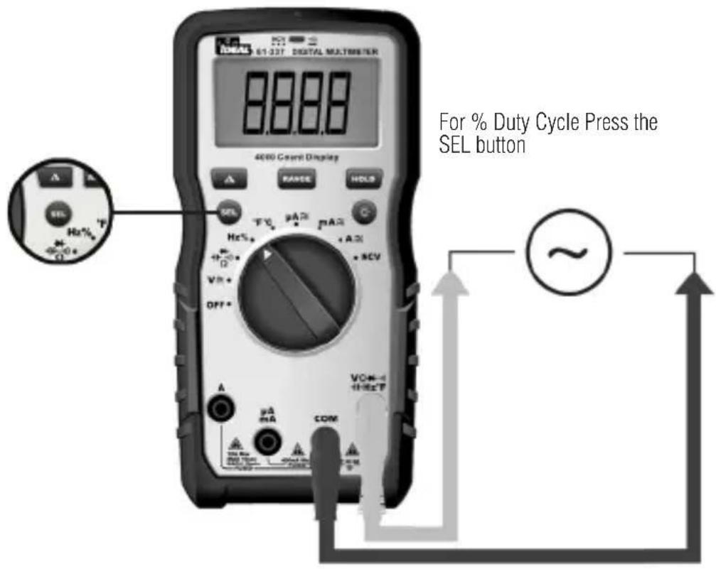
Measuring Frequency (Hz)
Hz using Voltage
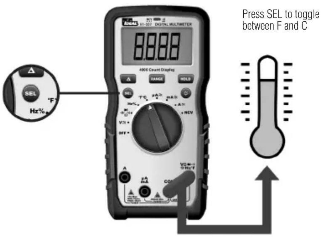
Measuring Temperature (°F °C)
Measuring Micro Amps (μA)
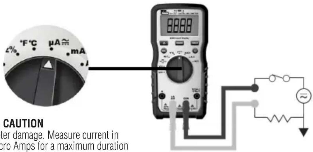

CAUTION
Meter damage. Measure current in Micro Amps for a maximum duration of 10 minutes. Failure to comply can result in meter damage.
Measuring Milli Amps (mA)
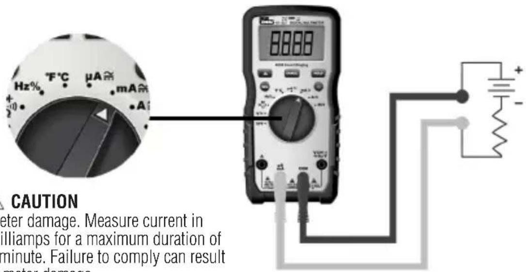

CAUTION
Meter damage. Measure current in Milliamps for a maximum duration of 1 minute. Failure to comply can result in meter damage..
Measuring Amps (A)
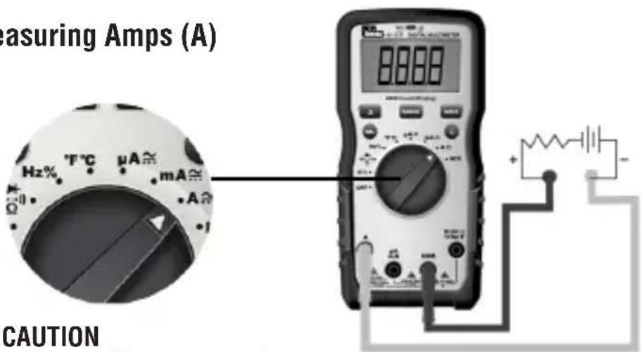

CAUTION
Meter damage. Measure current in Amps for a maximum duration of 10 seconds. Failure to comply can result in meter damage.
Functions Operation Table
| Button Response Default Function | ||
| HOLD | HOLD: All Functions Normal Measurement | |
SEL /  | ACA / DCA DCA | |
| ACV/DCV ACV | ||
| Hz/% Hz | ||
 | Continuity | |
| °F/°C °F | ||
| RANGE ACV, DCV, ACA, DCA, Ω | Auto range (LCD display “AUTO”) | |
 | Δ: ACV, DCV, ACA, DCA, CAP, Ω, °F/°C | Normal Measurement |
| Non-Contact Voltage Indication | ||
| Short Press: Circularly enter or exit the data hold mode, LCD will display “H” after enter HOLD function. | ||
| 1) Short press: Circularly select the relative measurement function.2) When in HOLD, RANGE, MAX/MIN, REL function, Short press the SEL key to quit current function and circularly change relative Select function. | ||
| 1) Short press the RANGE key to enter manual range mode (LCD will not display “AUTO”), and the current range, press again to enter cyclical selection range. Long press: exits manual range and enters Auto range. Switching measurement setting or restarting the unit returns the unit to the default setting.2) In HOLD, MAX/MIN, REL function, Short press the RANGE key to exit the current function and enter the relative range function. | ||
| 1) Short press: Circularly enter or exit REL function (when entering REL function, LCD will display “△” symbol)2) Entering the REL function, exits auto range and enters into the current range.3) Entering the REL measurement mode does not change the actual measurable range of the current range4) When HOLD or MAX/MIN is in use, REL function is invalid. | ||
| Displays “EF” – Electromagnetic Field | ||
Functions Indication Table
| Function Description | |
| Auto Range Auto | detects and displays most pertinent range for measured value. |
| LCD One LCD. | Displays a “-” symbol for all negative readings, displays “AC” for alternating current or “DC” for direct current and displays “Amps” for current measurement. |
| LCD Backlight White | backlight. The backlight will automatically power off after 5 minutes of inactivated |
| High Voltage Alarm | 1) Only applicable to ACV / DCV2) For ACV and DCV, when voltages in excess of 30V is measured or the measured voltage is over limit, then the high voltage alarm symbol “[gyks] appears on the screen display, simultaneously the LED remains RED and beeping lasts for 1 second then becomes silent during measurement. |
| Regular Prompt 1) | When turning the dial switch to any setting position except OFF, the buzzer will beep one time and the NCV LED flashes one time.2) When the button selection is valid, the buzzer will beep one time; When the button is invalid, the buzzer will beep twice.3) About 1 minute before the automatic shutdown, the buzzer will beep 5 times continuously, and 1 long beep before the unit shuts down.4) When the automatic shutdown function is canceled, the buzzer will beep 5 times when it reaches the APO time setting. |
| Over Range Indication | LCD displays “OL” when over range is encountered. |
| Lead Warning When inserting the test lead into any amperage input terminal, but the rotary function switch IS NOT set to the relative amperage position, the meter will beep at 3Hz, LCD will display "LEAd" and “”, flashes at 3Hz. If any amperage function is selected first, but the test lead IS NOT in relative amperage input jack,the meter will also beep at 3Hz and the LCD will display "LEAd" and “”, flashes at 3Hz. | |
| Function Description | |
| Fuse Notification | The test leadsCANNOTbe short circuited or used for measuring while testing the fuse.1. If the 400mA/600V fuse is blown, setting the rotary switch to the “mA” or “uA” setting, the LCD will display“FUSE” and “▲”, and the buzzer will beep continuously at the same time.2. If the 10A/600V fuse is blown, setting the rotary switch to the “A” setting, the LCD will display“FUSE” and “▲”, and the buzzer will beep continuously at the same time. |
| Low Battery Indication | When the battery voltage <3.6 ±0.2V, the low battery indication “■” is displayed on the screen and the meter will still work normally. When the battery voltage drops to less than 3.1 ±0.2V, “bAtt” is displayed for 5 seconds then shuts off. When the battery voltage is less than 3.2V, accuracy is no longer assured. |
| APO The unit will be automatically power off after 30 minutes of inactivity and enter the low-power state. Current draw is approx. ≤50 micro A. | |
| Restore APO All the buttons can wake up the unit, or rotate the dial switch to the OFF setting and then turn the unit back on to wake it up. | |
| Disable Auto Power Off Function | Pressing the “Select” key while turning on the unit on at the same time, will cancel the auto shutdown function. Buzzer will beep 5 times and the LCD will not display the “APO” symbol. |
| Mechanical Housing | Single Injection Molding with rubber boot. |
Electrical Specifications
| Function Range | 61-337 | Resolution Accuracy | |
| AC Voltage (V) TRMS | 400mV 0.1mV ±(1.5%+8) | ||
| 4V 0.001V | |||
| 40.00V 0.01V | |||
| 400.0V 0.1V | |||
| 600.0V 1V | |||
| AC Current (A) TRMS | 400.0μA 0.1μA | ||
| 4000μA 1μA | |||
| 40.00mA 0.01mA | |||
| 400.0mA 0.1mA | |||
| 4.000A 0.001A | |||
| 10.00A 0.01A | |||
| DC Voltage (V) | 400mV 0.1mV ±(1.5%+8) | ||
| 4V 0.001V | |||
| 40.00V 0.01V | |||
| 400.0V 0.1V | |||
| 600.0V 1V | |||
| DC Current (A) | 400.0μA 0.1μA | ||
| 4000μA 1μA | |||
| 40.00mA 0.01mA | |||
| 400.0mA 0.1mA | |||
| 4.000A 0.001A | |||
| 10.00A 0.01A | |||
| Resistance (Ω) | 400.0Ω 0.1Ω | ||
| 4.000kΩ 0.001kΩ | |||
| 40.00kΩ 0.01kΩ | |||
| 400.0kΩ 0.1kΩ | |||
| 4.000MΩ 0.001MΩ | |||
| 40.00MΩ 0.01MΩ | |||
| Function Range | 61-337 | Resolution Accuracy | |
| Capacitance | 400.0nF 0.1nF | ±(a%+b) | |
| 4.000uF 0.001uF | |||
| 40.00uF 0.01uF | |||
| 400.0uF 0.1uF | |||
| 4000uF 1uF | ±10% | ||
| Frequency Hz | 9.999Hz ~ 9.999KHz | 0.001Hz ~ 0.1KHz | ±(0.5%+5) |
| Duty Cycle % | 0.1%~99.9% | 0.1% | |
| Temp. °F -40~1832°F 1°F | ±(2.0%+7)@-40~32°F ±(2.0%+6)@33~1832°F | ||
| Temp. °C | -40~1000°C 1°C | ±(2.0%+4)@-40~0°C ±(2.0%+3)@1~1000°C | |
| Continuity |  | 0.1 Ω | ≤10Ω: Buzzer beeps and red indicator LED illuminates continuously |
| ≥70Ω: No buzzer beep | |||
| Diode test |  | 0.001V | Silicon PN joint with forward voltage about 0.5V to 0.8V |
| NCV | 40-600V | ≥40V/(50~60Hz), with direct wire contact, red indicator LED flashes at a frequency of 3Hz, and the buzzer beeps at a frequency of 3Hz simultaneously | |
- Overload Protection: 600VRMS MAX Fuses FF 0.4A 600V and F 10 A 600V
- Accuracy a is % of reading and b is LSD (Least Significant Digit).
Environmental Specifications
| Operating Temperature: | 32°F to 86°F (0°C to 30°C) (80%RH)86°F to 140°F (30°C to 40°C) (75%RH)104°F to 122°F (40°C to 50°C) (45%RH) |
| Operating Altitude: | < 6500 ft (< 2000 m) |
| Storage Temperature: | 14°F to 140°F (-10°C to 60°C) (<80%RH) |
Intended for indoor use
Mechanical Specifications
| Dimensions (L x W x H) 6.54 in. x 3.23 | in. x 1.89 in.(166 mm. x 82 mm. x 48 mm.) |
| Weight 0.675 LBS (0.306 KG) | |
| Display: LCD | |
| Display Count 4000 | |
| Power Source: 3 x 1.5V AAA | |
| Battery Life: 100 Hours Typical |
EMC/EMI
CISPR 22 3rd Edition. Class B Limits.
EN 55032
CISPR 32
CISPR 11
FCC 15. 107 with reference to Section 15.109 (g).
ICES-003
EN 61326-2-2 Sec 6.4.2.101
USA (FCC)
47 CFR 15 subpart B. This product is considered an exempt device per clause 15.103.
Safety
Complies with the following: UL 61010-1, 3rd Edition, May 11, 2012, Revised November 21 2018, CAN/CSA-C22.2 No. 61010-1-12, 3rd Edition, Amendment 1:2018, Revision dated November 21 2018, IEC 61010-2-033: 2019 Overvoltage CAT IV 600V CAT III 1000V. Any voltages exceeding the defined maximum voltage measurement categories described above are outside the normal use of the equipment and protection cannot be guaranteed. Pollution Degree Class 2
Maintenance and Service
Equipment Maintenance and Service
Meter Inspection
Do not use if meter appears damaged. Visually inspect the meter to ensure the case is not cracked.
Test Lead Inspection
Inspect and replace test leads if insulation is damaged, metal is exposed, or probes are cracked. Pay particular attention to the insulation surrounding the connectors.
Thermocouple Inspection
Inspect the thermocouple for signs of wear or breakage. Replace if necessary to guarantee accuracy of readings.
Battery Inspection/Replacement
Inspect the battery compartment monthly for any signs of degradation. Low battery voltages will cause inaccuracies in readings. Remove the batteries for storage or if the meter will not be used for longer than one month. Battery leakage will compromise the safety of the meter and cause irreparable damage to internal components.
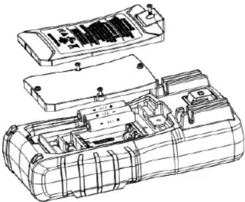
natural_image
Technical line drawing of a mechanical device with internal compartments and housing (no text or symbols)
Shock Hazard. Remove the test leads from the circuit prior to removing the battery cover. Failure to comply can result in serious injury or death.
Maintenance and Storage
Switch off and disconnect the meter completely before carrying out an maintenance. Clean the case with a damp cloth and mild detergent. Do not use abrasives or solvents. Keep away from liquids and ensure the meter is completely dry before use.
Service and Replacement Parts
- For the 10 Amp Terminal – 10 Amp 600V AC DC, 6 x 32 mm Ceramic or equivalent
- For the 400 Milli Amp Terminal – 400 Milli Amp 600V AC DC, 6 x 32 mm Ceramic or equivalent
- To ensure the meter is in a safe state of operation, make sure the fuses are properly seated and that the battery cover is secured to the back of the meter. With the leads in the terminals but not connected to or touching any voltage source, turn the function dial to the applicable Amperage setting and verify the FUSE indicator is NOT displayed. This indicates that the replacement fuse in not blown or popped. Use only specified replacement fuses.
Disposal of Waste, Electrical & Electronic Equipment

In order to preserve, protect and improve the quality of the environment, protect human health and utilize natural resources prudently and rationally, the user should return unserviceable product to relevant facilities in accordance with statutory regulations. The crossed-out wheeled bin indicates the product needs to be disposed separately and not as municipal waste.
Do not dispose of this product as unsorted municipal waste. It must be properly disposed of in accordance with local regulations. Please see www.epa.gov or www.erecycle.org for additional information.
Disposal of Used Batteries/Accumulators
The user is legally obliged to return used batteries and accumulators. Disposing used batteries in household waste is prohibited! Batteries/accumulators containing hazardous substances are marked with the crossed-out wheeled bin. The symbol indicates that the product is forbidden to be disposed via domestic refuse. The chemical symbols for the respective hazardous substances are Cd = Cadmium, Hg = Mercury, Pb = Lead.
You can return used batteries/accumulators free of charge to any collecting point of your local authority, our stores, or where batteries/accumulators are sold. Consequently, you must comply with your legal obligations and contribute to environmental protection.
TWO YEAR LIMITED WARRANTY
This tester is warranted to the original purchaser against defects in material and workmanship for a period of two (2) years from date of purchase. With proof of purchase from an authorized IDEAL distributor, a defective tester will be repaired or replaced with the same product or a functionally equivalent product, at the option of IDEAL INDUSTRIES, INC. during the warranty period, subject to verification of the defect or malfunction. Warranty does not cover consumables such as fuses, batteries, and excludes defects caused by leakage from batteries, abuse, mishandling, dropping, ordinary wear and tear, misuse, neglect, unauthorized repair, improper use, alterations, accidents or any causes beyond IDEAL's reasonable control. Consequential or incidental damages are not recoverable under this warranty. Some states do not allow the exclusion or limitation of incidental or consequential damages, so the above limitation or exclusion may not apply to you. This LIMITED WARRANTY gives you specific legal rights, which vary from state to state. This warranty constitutes the sole and exclusive remedy of the purchaser and the exclusive liability of IDEAL, and is in lieu of any and all other warranties, and expressly disclaims all other warranties, implied, or statutory as to merchantability, fitness for purpose sold, description, quality productiveness, or any other matter. No agent, distributor or other supplier has the authority to modify or amend this warranty or make other representations or warranties other than those contained in this warranty without express written authorization from IDEAL. For warranty service, call IDEAL customer service at 1-800-435-0705.
IDEAL INDUSTRIES, INC. Sycamore, IL 60178, U.S.A. 800-435-0705 w/w.idealind.com ND 9018-2
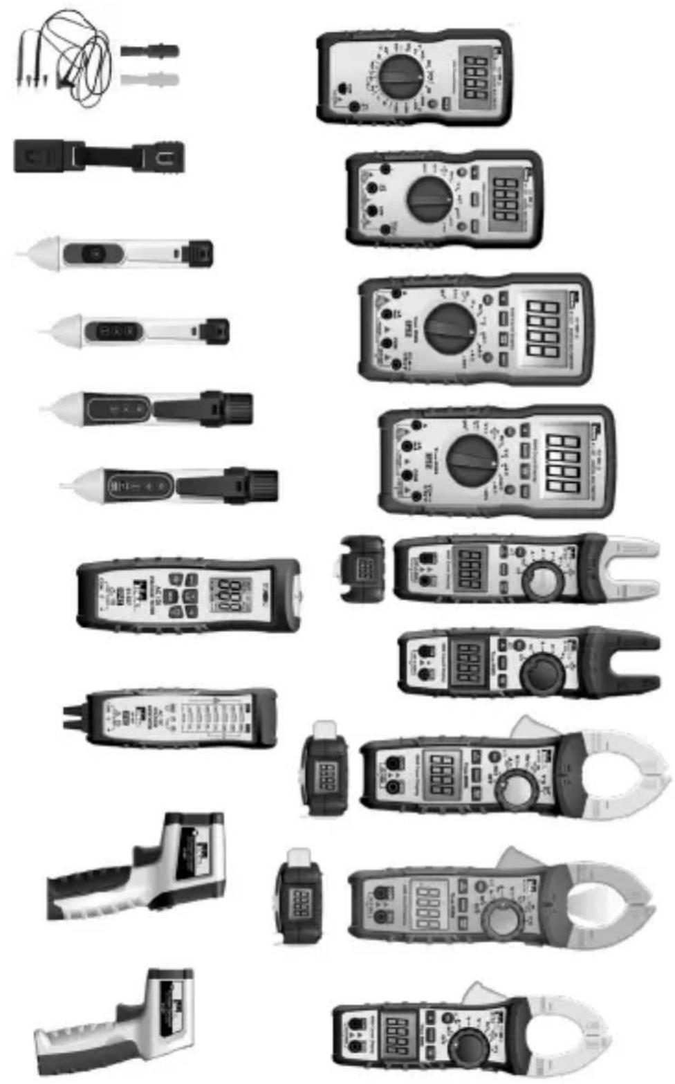
natural_image
Collection of various analog multimeters and probes displayed in a grid layout (no visible text or labels)Scan the barcode on the right to see the new IDEAL T&M Product Line


SCAN ME
IDEAL Industries Australia

Información
natural_image
Technical line drawing of a mechanical device with internal compartments and housing (no text or symbols)

ADVERTENCIA
natural_image
Collection of various analog multimeters and probes displayed in a grid layout (no visible text or labels)
SCAN ME
Introduction......63
Avertissements,....64-65
Précautions 65
Symboles....66-67
IDEAL Industries Australia

Functions Indication Table
CISPR 22 3rd Edition. Class B Limits. EN 55 032
CISPR 32
CISPR 11
natural_image
Technical line drawing of a mechanical device with internal compartments and mounting points (no text or symbols)