
Maximus VII Formula/Watch Dogs - Bag ASUS - Free user manual and instructions
Find the device manual for free Maximus VII Formula/Watch Dogs ASUS in PDF.
| Product type | Gaming backpack |
| Brand | Asus |
| Model | Maximus VII Formula / Watch Dogs |
| Dimensions (H x W x D) | 45 x 32 x 18 cm |
| Weight | Approximately 1.2 kg |
| Volume | Approximately 25 liters |
| Main material | 600D polyester with water-repellent coating |
| Laptop compartment | Yes, up to 17.3 inches |
| Number of pockets | Zippered main pocket, zippered front pocket, elastic side pockets |
| Straps | Adjustable chest and waist straps |
| Comfort | Padded back with ventilation system, ergonomic shoulder straps |
| Zipper | Durable zippers with ROG-branded pulls |
| Recommended use | Transporting a gaming laptop, accessories, and personal items |
| Care and cleaning | Clean with a damp cloth and mild soap. Do not machine wash. |
| Safety | Complies with general safety standards. No hazardous substances. |
| Spare parts and repairability | No spare parts available separately. Repair possible at a specialized workshop. |
Frequently Asked Questions - Maximus VII Formula/Watch Dogs ASUS
User questions about Maximus VII Formula/Watch Dogs ASUS
0 question about this device. Answer the ones you know or ask your own.
Ask a new question about this device
Download the instructions for your Bag in PDF format for free! Find your manual Maximus VII Formula/Watch Dogs - ASUS and take your electronic device back in hand. On this page are published all the documents necessary for the use of your device. Maximus VII Formula/Watch Dogs by ASUS.
USER MANUAL Maximus VII Formula/Watch Dogs ASUS
Offer to Provide Source Code of Certain Software
This product may contain copyrighted software that is licensed under the General Public License (“GPL”) and under the Lesser General Public License Version (“LGPL”). The GPL and LGPL licensed code in this product is distributed without any warranty. Copies of these licenses are included in this product.
You may obtain the complete corresponding source code (as defined in the GPL) for the GPL Software, and/or the complete corresponding source code of the LGPL Software (with the complete machine-readable "work that uses the Library") for a period of three years after our last shipment of the product including the GPL Software and/or LGPL Software, which will be no earlier than December 1, 2011, either
(1) for free by downloading it from http://support.asus.com/download;
or
(2) for the cost of reproduction and shipment, which is dependent on the preferred carrier and the location where you want to have it shipped to, by sending a request to:
ASUSTeK Computer Inc.
Legal Compliance Dept.
15 Li Te Rd.,
Beitou, Taipei 112
Taiwan
In your request please provide the name, model number and version, as stated in the About Box of the product for which you wish to obtain the corresponding source code and your contact details so that we can coordinate the terms and cost of shipment with you.
The source code will be distributed WITHOUT ANY WARRANTY and licensed under the same license as the corresponding binary/object code.
This offer is valid to anyone in receipt of this information.
ASUSTeK is eager to duly provide complete source code as required under various Free Open Source Software licenses. If however you encounter any problems in obtaining the full corresponding source code we would be much obliged if you give us a notification to the email address gpl@asus.com, stating the product and describing the problem (please do NOT send large attachments such as source code archives etc to this email address).
Table des matières
3.5 Menu Main (Principal) 3-24
3.6 Menu Advanced (Avancé).... 3-26
3.6.1 CPU Configuration (Configuration du CPU) 3-27
3.6.2 PCH Configuration (Configuration PCH) 3-30
3.6.3 PCH Storage Configuration
(Configuration de stockage) 3-31
3.6.4 System Agent Configuration
(Configuration d'agent système) 3-33
3.6.5 USB Configuration (Configuration USB) 3-34
3.6.6 Platform Misc Configuration
(Paramètres de plate-forme) 3-35
3.6.7 Onboard Devices Configuration
(Configuration des périphériques embarqués) ...... 3-36
3.6.8 APM (Gestion d'alimentation avancée) 3-39
3.6.9 Network Stack (Pile réseau) 3-40
3.6.10 ROG Effects (Effets ROG) 3-40
3.7 Menu Monitor (Surveillance) 3-41
Contacter ASUS....A-5
natural_image
Line drawing of a desktop computer tower case with ventilation grilles and control panel (no text or symbols)natural_image
Line drawing of a mechanical fan or turbine with three legs and a central hub (no text or symbols)
natural_image
Simple line drawing of a layered object with no text or symbolsnatural_image
Isometric line drawing of a rectangular electronic component with mounting holes and a central oval cavity (no text or symbols)Disque(s) dur(s) SATA
natural_image
Line drawing of a screwdriver with a flat head and pointed tip (no text or symbols)Tournevis Philips (croix)
natural_image
Illustration of a white rectangular box with two electrical outlets on one side (no text or symbols)Bloc d'alimentation
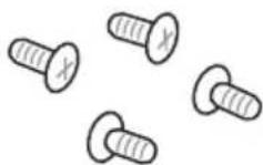
1 sachet de vis

natural_image
Line drawing of a 8-pin RAM module (no text or symbols)Module(s) mémoire
natural_image
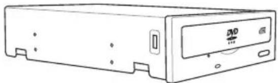
Line drawing of a rectangular electronic device with a central DVD drive and ports (no text or symbols)natural_image
Technical line drawing of a mechanical or electronic component with no visible text or symbolsExtreme Engine Digi+ III
text_image
ASUS RESOURCES OF FORMULSInterface de connexion LGA1150 de la MAXIMUS VII FORMULA

text_image
DIMM_A1 DIMM_A2 DIMM_B1 DIMM_B2 ASUS RESIDE W PONECOtext_image
DIMM_A2 DIMM_A2 DIMM_B2 DIMM_A1 DIMM_A2 DIMM_B1 DIMM_B2Configurations mémoire
http://support.microsoft.com/kb/929605/en-us.
| Vendors Part No. Size | SS/DS | Chip Brand | Chip NO. | Timing Voltage | DIMM socket support (Optional) | ||
| 2 | 4 | ||||||
| G.SKILL FE-3300C13D-8GTXDG (XMP) | 8GB ( 2x 4GB ) SS - - 13-15-15-35 1.65 | • | |||||
DDR3 3200 MHz
| Vendors Part No. Size | SS/DS | Chip Brand | Chip NO. | Timing Voltage | DIMM socket support (Optional) | ||
| 2 | 4 | ||||||
| AVEXIR "AVD3UH32001304G-4CI(XMP)" | 16GB (4x 4GB) SS - - 13-15-15-35 1.65 • • | ||||||
| G.SKILL "F3-3200C12Q-16GTXDG(XMP)" | 16GB (4x 4GB) SS - - 12-15-15-35 1.65 • • | ||||||
DDR3 3100 MHz
| Vendors Part No. Size | SS/DS | Chip Brand | Chip NO. | Timing Voltage | DIMM socket support (Optional) | |
| 2 | 4 | |||||
| AVEXIR "AVD3UH31001204G-4CI(XMP)" | 16GB (4x 4GB) SS - - 12-14-14-35 1.65 • • | |||||
| A-DATA "AX3U3100W4G12-DMV(XMP)" | 8GB (2x 4GB) SS - - 12-14-14-36 1.65 • • | |||||
DDR3 3000 MHz
| Vendors Part No. | Size | SS/DS | Chip Brand | Chip NO. | Timing Voltage | DIMM socket support (Optional) | |
| 2 | 4 | ||||||
| AVEXIR "AVD3UH30001204G-4BZ1(XMP)" | 16GB (4x 4GB) SS - - 12-14-14-35 1.65 • • | ||||||
| G.SKILL "G.SKILL F3-3000C12Q-16GTXDG(XMP)" | 16GB (4x 4GB) SS - - 12-14-14-35 1.65 • • | ||||||
| G.SKILL "F3-3000C12D-8GTXDG(XMP)" | 8GB (2 x 4B ) SS - - 12-14-14-35 1.65 • • | ||||||
| CORSAIR "CMY8GX3M2A-3000C12R(XMP)" | 8GB (2 x 4B ) SS - - 12-14-14-36 1.65 • | ||||||
DDR3 2933 MHz
| Vendors Part No. Size | SS/DS | Chip Brand | Chip NO. | Timing Voltage | DIMM socket support (Optional) | ||||
| 2 | 4 | ||||||||
| G.SKILL | F3-2933C12D-8GTXDG(XMP) | 8GB (2 x 4GB ) | SS | - | - | 12-14-14-35 | 1.65 | • | • |
| G.SKILL | F3-2933C12Q-16GTXDG(XMP) | 16GB (4 x 4GB ) | SS | - | - | 12-14-14-35 | 1.65 | • | • |
| G.SKILL | F3-2933C12D-16GTXDG(XMP) | 16GB (2 x 8GB ) | DS | - | - | 12-14-14-35 | 1.65 | • | • |
| G.SKILL | F3-2933C12Q-32GTXDG(XMP) | 32GB (4 x 8GB ) | DS | - | - | 12-14-14-35 | 1.65 | • | • |
| CORSAIR | CMY16GX3M4A2933C12R(XMP) | 16GB ( 4x 4GB ) | SS | - | - | 12-14-14-36 | 1.65 | • | • |
DDR3 2800 MHz
| Vendors | Part No. | Size | SS/DS | Chip Brand | Chip NO. | Timing | Voltage | DIMM socket support (Optional) | |
| 2 | 4 | ||||||||
| AVEXIR | AVD3UH28001208G-4BZ1(XMP) | 32GB ( 4x 8GB ) | DS | - | - | 12-14-14-35 | 1.65 | • | • |
| A_DATA | AX3U2800W4G12(XMP) | 16GB ( 4x 4GB ) | SS | - | - | 12-14-14-36 | 1.65 | • | • |
| A_DATA | AX3U2800W8G12(XMP) | 32GB ( 4x 8GB ) | DS | - | - | 12-14-14-36 | 1.65 | • | |
| G.SKILL | F3-2800C12Q-32GTXD(XMP) | 32GB ( 4x 8GB ) | DS | - | - | 12-13-13-35 | 1.65 | • | • |
| G.SKILL | F3-2800C12Q-32GTXDG(XMP) | 32GB ( 4x 8GB ) | DS | - | - | 12-14-14-35 | 1.65 | • | • |
| G.SKILL | F3-2800C11Q-16GTXD(XMP) | 16GB ( 4x 4GB ) | DS | - | - | 11-13-13-35 | 1.65 | • | • |
| G.SKILL | F3-2800C11D-8GTXD(XMP) | 8GB ( 2x 4GB ) | DS | - | - | 11-13-13-35 | 1.65 | • | • |
| G.SKILL | F3-2800C11D-8GTXDG(XMP) | 8GB ( 2x 4GB ) | DS | - | - | 11-14-14-35 | 1.65 | • | • |
| G.SKILL | F3-2800C11Q-16GTXDG(XMP) | 16GB ( 4x 4GB ) | DS | - | - | 11-14-14-35 | 1.65 | • | • |
| G.SKILL | F3-2800C10D-8GTXD(XMP) | 8GB ( 2x 4GB ) | DS | - | - | 10-12-12-35 | 1.65 | • | • |
| G.SKILL | F3-2800C12Q-16GTXDG(XMP) | 16GB ( 4x 4GB ) | DS | - | - | 12-14-14-35 | 1.65 | • | • |
| G.SKILL | F3-2800C11D-16GTXDG(XMP) | 16GB (2 x 8GB ) | DS | - | - | 11-14-14-35 | 1.65 | • | • |
| G.SKILL | F3-2800C11Q-32GTXDG(XMP) | 32GB (4 x 8GB ) | DS | - | - | 11-14-14-35 | 1.65 | • | • |
| G.SKILL | F3-2800C11D-16GTXD(XMP) | 16GB (2x 8GB ) | DS | - | - | 11-13-13-35 | 1.65 | • | • |
| G.SKILL | F3-2800C11Q-32GTXD(XMP) | 32GB (4 x 8GB ) | DS | - | - | 11-13-13-35 | 1.65 | • | • |
| G.SKILL | F3-2800C12D-16GTXD(XMP) | 16GB (2 x 8GB ) | DS | - | - | 12-14-14-35 | 1.65 | • | • |
| APACER | 78.BAGH5.AFD0C(XMP) | 8GB ( 2x 4GB ) | DS | - | - | 12-14-14-35 | 1.65 | • | |
| CORSAIR | CMD16GX3M4A2800C11(XMP) | 16GB ( 4x 4GB ) | DS | - | - | 11-14-14-35 | 1.65 | • | • |
| CORSAIR | CMD16GX3M4A2800C12(XMP) | 16GB ( 4x 4GB ) | DS | - | - | 12-14-14-36 | 1.65 | • | • |
| CORSAIR | CMY16GX3M4A2800C12R(XMP) | 16GB ( 4x 4GB ) | SS | - | - | 12-14-14-36 | 1.65 | • | • |
| KINGSTON | KHX28C12T2K2/8X | 8GB ( 2x 4GB ) | SS | - | - | 12-14-14-32 | 1.65 | • | • |
DDR3 2666 MHz
| Vendors Part No. Size | SS/DS | Chip Brand | Chip NO. | Timing Voltage | DIMM socket support (Optional) | ||||
| 2 | 4 | ||||||||
| Apacer | 78.BAGFF.AFC0C(XMP) | 8GB ( 2x 4GB ) | DS | - | - | 12-13-13-35 | - | • | • |
| Apacer | 78.BAGFR.AFD0C(XMP) 8GB ( 2x 4GB ) DS - - 12-13-13-35 - • • | ||||||||
| Apacer | 78.CAGFF.AFD0C(XMP) | 16GB ( 2x 8GB ) | DS | - | - | 12-13-13-35 | - | • | • |
| CORSAIR | CMD16GX3M4A2666C11(Ver5.12)(XMP) | 16GB ( 4x 4GB ) | DS | - | - | 11-13-13-35 | 1.65 | • | • |
| G.SKILL | F3-2666CL10Q-16GBZHD(XMP) | 16GB ( 4x 4GB ) | DS | - | - | 10-12-12-31 | 1.65 | • | • |
| Gell | GOC332GB2666C11QC(XMP) | 32GB ( 4x 8GB ) | DS | - | - | 11-13-13-32 | 1.65 | • | • |
| Kingston | KHX26C11T2K2/8X(XMP) | 8GB ( 2x 4GB ) | SS | - | - | 2666-11-13-13-32 | 1.65 | • | |
DDR3 2400 MHz
| Vendors Part No. Size SS/DS | Chip Brand | Chip NO. | Timing Voltage | DIMM socket support (Optional) | ||||
| 2 | 4 | |||||||
| ADATA | AX3U2400W4G11-DMV(XMP) | 8GB ( 2x 4GB ) | SS | - | - | 11-13-13-35 | 1.65 | • |
| ADATA | AX3U2400W8G11-DMV(XMP) | 16GB ( 2x 8GB ) | DS | - | - | 11-13-13-35 | 1.65 | • |
| Apacer | 78.BAGFL.AFD0C(XMP) | 8GB ( 2x 4GB ) | DS | - | - | 11-12-12-30 | - | • |
| Apacer | 783BAGF3.AFD0C(XMP) | 8GB ( 2x 4GB ) | DS | - | - | 11-11-11-30 | - | • |
| CORSAIR CMD16GX3M2A2400C10(Ver4.21)(XMP) | 16GB ( 2x 8GB ) | DS | - | - | 10-12-12-31 | 1.65 | • | |
| CORSAIR CMD32GX3M4A2400C10(Ver5.29)(XMP) | 32GB ( 4x 8GB ) | DS | - | - | 10-12-12-31 | 1.65 | • | |
| CORSAIR CMD32GX3M4A2400C10(Ver4.21)(XMP) | 32GB ( 4x 8GB ) | DS | - | - | 10-12-12-31 | 1.65 | • | |
| CORSAIR CMY16GX3M2A2400C10A(Ver4.21)(XMP) | 16GB ( 8x 2GB ) | DS | - | - | 10-12-12-31 | 1.65 | • | |
| CORSAIR CMY16GX3M2A2400C10R(Ver4.21)(XMP) | 16GB ( 2x 8GB ) | DS | - | - | 10-12-12-31 | 1.65 | • | |
| CORSAIR CMZ16GX3M2A2400C10(Ver4.21) | 16GB ( 2x 8GB ) | DS | - | - | 10-12-12-31 | 1.65 | • | |
| G.SKILL | F3-19200CL10Q2-64GBZHD(XMP) | 64GB ( 8x 8GB ) | DS | - | - | 10-12-12-31 | 1.65 | • |
| G.SKILL | F3-19200CL10Q-32GBZHD(XMP) | 32GB ( 4x 8GB ) | DS | - | - | 10-12-12-31 | 1.65 | • |
| G.SKILL | F3-19200CL11Q-16GBZHD(XMP) | 16GB ( 4x 4GB ) | DS | - | - | 11-11-11-31 | 1.65 | • |
| G.SKILL | F3-19200CL9D-4GBPIS(XMP) | 4G ( 2x 2G ) | DS | - | - | 9-11-9-28 | 1.65 | • |
| G.SKILL | F3-19200CL9Q-16GBZMD(XMP) | 16GB ( 4x 4GB ) | DS | - | - | 9-11-11-31 | 1.65 | • |
| G.SKILL | F3-2400C11Q-32GXM(XMP) | 32GB ( 4x 8GB ) | DS | - | - | 11-13-13-31 | 1.65 | • |
| GeIL | GOC316GB2400C10QC(XMP) | 16GB ( 4x 4GB ) | DS | - | - | 10-11-11-30 | 1.65 | • |
| GeIL | GOC316GB2400C11QC(XMP) | 16GB ( 4x 4GB ) | DS | - | - | 11-11-11-30 | 1.65 | • |
| Kingston | KHX2400C11D3K4/8GX(XMP) | 8GB ( 4x 2GB ) | SS | - | - | 11-13-11-30 | 1.65 | • |
| Kingston | KHX24C11K4/16X(XMP) | 16GB ( 4x 4GB ) | DS | - | - | 11-13-13-30 | 1.65 | • |
| Kingston | KHX24C11T2K2/8X(XMP) | 8GB ( 2x 4GB ) | DS | - | - | - | 1.65 | • |
| Kingston | KHX24C11T3K4(XMP) | 16GB ( 4x 4GB ) | DS | - | - | 2400-11-13-13-30 | 1.65 | • |
| Kingston | KHX24C11T3K4/32X(XMP) | 32GB ( 4x 8GB ) | DS | - | - | 9-9-9-24 | 1.65 | • |
| mushkin | 997122R(XMP) | 16GB ( 2x 8GB ) | DS | - | - | 2400-10-12-12-28 | 1.65 | • |
| Silicon Power | SP004GXLYU240NSA(XMP) | 4GB | SS | - | - | 2400-11-13-13-32 | - | •• |
| Team | TLD38G2400HC11CBK(XMP) | 8GB | DS | - | - | 11-13-13-35 | 1.65 | • |
| Transcend | TX2400KLN-8GK(XMP) | 8GB ( 2x 4GB ) | DS | - | - | 2400-11-12-11-29 | 1.6 | • |
DDR3 2133 MHz
| Vendors Part No. Size | SS/DS | Chip Brand | Chip NO. | Timing Voltage | DIMM socket support (Optional) | ||||
| 2 | 4 | ||||||||
| ADATA | AX3U2133W4G10-DR(XMP) | 8GB ( 2x 4GB ) | SS | - | - | 10-11-11-30 | 1.65 | • | • |
| ADATA | AX3U2133W8G10-DR(XMP) | 16GB ( 2x 8GB ) | DS | - | - | 10-11-11-30 | 1.65 | • | • |
| Apacer | 78.BAGE4.AFD0C(XMP) | 8GB ( 2x 4GB ) | DS | - | - | 9-9-9-24 | - | • | • |
| Apacer | AHU04GFB33CAQ3R(XMP) | 4GB | DS | - | - | 11-13-13-31 | - | • | • |
| CORSAIR | CMD16GX3M2A2133C9 (Ver4.21)(XMP) | 16GB ( 2x 8GB ) | DS | - | - | 9-11-11-31 | 1.65 | • | • |
| CORSAIR | CMD32GX3M4A2133C9 (Ver4.21)(XMP) | 32GB ( 4x 8GB ) | DS | - | - | 9-11-11-31 | 1.65 | • | • |
| CORSAIR | CMD8GX3M2A2133C9 (Ver1.5)(XMP) | 8GB ( 2x 4GB ) | DS | - | - | 9-11-10-27 | 1.5 | • | |
| CORSAIR | CMD8GX3M2B2133C9 (Ver5.12)(XMP) | 8GB ( 2x 4GB ) | DS | - | - | 9-11-11-31 | 1.65 | • | • |
| CORSAIR | CMY8GX3M2A2133C11R (Ver4.21)(XMP) | 8GB ( 2x 4GB ) | DS | - | - | 11-11-11-27 | 1.5 | • | • |
| CORSAIR | CMZ8GX3M2A2133C11R (Ver4.21)(XMP) | 8GB ( 2x 4GB ) | DS | - | - | 11-11-11-27 | 1.5 | • | • |
| G.SKILL F3-17000CL11Q2-64GBZLD(XMP) | 64GB ( 8x 8GB ) | DS | - | - | 11-11-11-30 | 1.5 | • | • | |
| G.SKILL F3-17000CL9Q-16GBZH(XMP) | 16GB ( 4x 4GB ) | DS | - | - | 9-11-10-28 | 1.65 | • | • | |
| G.SKILL | F3-2133C10Q-32GSR(XMP) | 32GB ( 4x 8GB ) | DS | - | - | 10-12-12-31 | 1.5 | • | • |
| G.SKILL | F3-2133C11Q-32GZL(XMP) | 32GB ( 4x 8GB ) | DS | - | - | 11-11-11-31 | 1.5 | • | • |
| Kingston | KHX2133C11D3K4/16GX(XMP) | 16GB ( 4x 4GB ) | DS | - | - | 11-12-11-30 | 1.65 | • | • |
| Kingston | KHX21C11T3FK8/64X(XMP) | 64GB ( 8x 8GB ) | DS | - | - | 9-9-9-24 | 1.5 | • | • |
| Silicon Power | SP004GXLYU213NSA(XMP) | 4GB | SS | - | - | 2133-11-12-11-30 | - | •• | |
| Silicon Power | SP008GXLYU213NSA(XMP) | 8GB | DS | - | - | 2133-11-12-11-30 | - | •• | |
| Team | TLD38G2133HC11ABK(XMP) | 8GB | DS | - | - | 11-11-11-31 | 1.65 | • | • |
| Transcend | TX2133KLH-16GK(XMP) | 16GB ( 2x 8GB ) | DS | - | - | 2133-10-11-10-27 | 1.6 • • | ||
| Transcend | TX2133KLN-8GK(XMP) | 8GB ( 2x 4GB ) | DS | - | - | 2133-10-11-10-27 | 1.6 • • | ||
DDR3 2000 MHz
| Vendors | Part No. | Size | SS/DS | Chip Brand | Chip NO. | Timing | Voltage | DIMM socket support (Optional) | |
| 2 | 4 | ||||||||
| AEXEA | AXA3ES4GK2000LG28V(XMP) | 4GB ( 2x 2GB ) | DS | - | - | - | 1.65 | • | • |
| ASint | SLA302G08-ML2HB(XMP) | 4GB | DS | Hynix | H5TQ2G83BFRH9C | 9-9-9-27 | - | • | • |
| GeIL | GUP34GB2000C9DC(XMP) | 4GB ( 2x 2GB ) | DS | - | - | 9-9-9-28 | 1.65 | • | • |
DDR3 1866 MHz
| Vendors Part No. Size | SS/DS | Chip Brand | Chip NO. | Timing Voltage | DIMM socket support (Optional) | ||||
| 2 | 4 | ||||||||
| CORSAIR CMD16GX3M2A1866C9 (Ver5.29)(XMP) | 16GB ( 2x 8GB ) DS - - 1866 9-9-9-27 1.5 · | ||||||||
| CORSAIR CMD16GX3M4A1866C9 (Ver4.13)(XMP) | 16GB ( 4x 4GB ) DS - - 9-10-9-27 1.5 · | ||||||||
| CORSAIR CMD16GX3M4A1866C9 (Ver8.16)(XMP) | 16GB ( 4x 4GB ) DS - - 9-10-9-27 1.5 · | ||||||||
| CORSAIR CMD32GX3M4A1866C9 (Ver3.24)(XMP) | 32GB ( 4x 8GB ) DS - - 9-10-9-27 1.5 · | ||||||||
| CORSAIR CMD8GX3M2A1866C9 (Ver4.13)(XMP) | 8GB ( 2x 4GB ) DS - - - 1.5 · | ||||||||
| CORSAIR CMD8GX3M2A1866C9 (Ver5.12)(XMP) | 8GB ( 2x 4GB ) DS - - 9-10-9-27 1.5 · | ||||||||
| CORSAIR CMD8GX3M2A1866C9 (Ver8.16)(XMP) | 8GB ( 2x 4GB ) DS - - 9-10-9-27 1.5 · | ||||||||
| CORSAIR CMT32GX3M4X1866C9(Ver3.23)(XMP) | 32GB ( 4x 8GB ) DS - - 9-10-9-27 1.5 · | ||||||||
| CORSAIR CMY16GX3M2A1866C9 (Ver 4.21)(XMP) | 16GB ( 2x 8GB ) DS - - 9-10-9-27 1.5 · | ||||||||
| CORSAIR CMY8GX3M2A1866C9 (Ver3.24)(XMP) | 8GB ( 2x 4GB ) DS - - 9-10-9-27 1.5 · | ||||||||
| CORSAIR CMZ16GX3M2A1866C10 (Ver5.29)(XMP) | 16GB ( 2x 8GB ) DS - - 10-11-10-30 1.5 · | ||||||||
| CORSAIR CMZ16GX3M2A1866C9(XMP) | 16GB ( 2x 8GB ) DS - - - 1866-9-10-9-27 1.5 · | ||||||||
| CORSAIR CMZ32GX3M4X1866C10 (Ver3.23)(XMP) | 32GB ( 4x 8GB ) DS - - 10-11-10-27 1.5 · | ||||||||
| CORSAIR CMZ32GX3M4X1866C10(Ver3.23)(XMP) | 32GB ( 4x 8GB ) DS - - 10-11-10-27 1.5 · | ||||||||
| CORSAIR CMZ8GX3M2A1866C9 (Ver8.16)(XMP) | 8GB ( 2x 4GB ) DS - - 9-10-9-27 1.5 · | ||||||||
| CORSAIR CMZ8GX3M2A1866C9(XMP) | 8GB ( 2x 4GB ) DS - - - 9-10-9-27 1.5 · | ||||||||
| CORSAIR CMZ8GX3M2A1866C9G (Ver5.12)(XMP) | 8GB ( 2x 4GB ) DS - - 1866 9-10-9-27 1.5 · | ||||||||
| crucial | BLE4G3D1869DE1XT0.16FMD(XMP) | 4GB | DS | - | - | 9-9-9-27 | 1.5 | · | · |
| crucial | BLE8G3D1869DE1TX0.16FED(XMP) | 16GB ( 2x 8GB ) | DS | - | - | 1866-9-9-9-27 | 1.5 | · | · |
| G.SKILL | F3-14900CL10Q-32GBZL(XMP) | 32GB ( 4x 8GB ) | DS | - | - | 10-11-10-30 | 1.5 | · | · |
| G.SKILL | F3-14900CL9D-8GBSR(XMP) | 8GB ( 2x 4GB ) | DS | - | - | 9-10-9-28 | 1.5 | · | · |
| G.SKILL | F3-14900CL9Q-16GBXL(XMP) | 16GB ( 4x 4GB ) | DS | - | - | 9-10-9-28 | 1.5 | · | · |
| G.SKILL | F3-14900CL9Q-16GBZL(XMP) | 16GB ( 4x 4GB ) | DS | - | - | 9-10-9-28 | 1.5 | · | · |
| G.SKILL | F3-14900CL9Q-16GBZL(XMP) | 16GB ( 4x 4GB ) | DS | - | - | 9-10-9-28 | 1.5 | • | · |
| G.SKILL | F3-1866C10Q2-64GZM(XMP) | 64GB ( 2x 8GB ) | DS | - | - | 10-11-10-30 | 1.5 | · | · |
| G.SKILL | F3-1866C10Q2-64GZM(XMP) | 64GB ( 2x 8GB ) | DS | - | - | 10-11-10-30 | 1.5 | · | · |
| G.SKILL | F3-1866C9Q-32GXM(XMP) | 32GB ( 4x 8GB ) | DS | - | - | 9-10-9-28 | 1.5 | · | · |
DDR3 1866 MHz
| Vendors Part No. Size | SS/DS | Chip Brand | Chip NO. Timing Voltage | DIMM socket support (Optional) | |||||
| 2 | 4 | ||||||||
| GeIL | GEEL316GB1866C9DC(XMP) | 16GB ( 2x 8GB ) | DS | - | - | 1866-9-10-9-28 | 1.65 • • | ||
| Kingston | KHX1866C9D3K2/8GX(XMP) | 8GB ( 2x 4GB ) | DS | - | - | - | 1.65 | • | • |
| Silicon Power | SP004GXLYU186NSA(XMP) | 4GB | SS | - | - | 1866-9-11-9-27 | - | • | • |
| Silicon Power | SP008GXLYU186NSA(XMP) | 8GB | DS | - | - | 1866-9-11-9-27 | - | • | • |
| Team | TED38GM1866C13BK | 8GB | DS | Hynix | H5TQ4G83AFR | 13-13-13-32 | 1.5 | • | • |
| V-color | TD4G16C13-RD | 4GB | DS | - | - | 1866-13-13-13-32 | 1.5 | • • | |
DDR3 1600 MHz
| Vendors Part No. Size SS/DS | Chip Brand | Chip NO. Timing Voltage | DIMM socket support (Optional) | ||||||
| 2 | 4 | ||||||||
| ADATA | AD3U1600W4G11 | 4GB | SS | A-DATA | 3WCD-1211A | 11-11-11-28 | -··· | ||
| ADATA | AD3U1600W8G11 | 8GB | DS | A-DATA | 3WCD-1211A | 11-11-11-28 | -··· | ||
| ADATA ADDU1600W4G11-B 4GB SS A-DATA DWND-1211A 9-9-9- | 24 | -··· | |||||||
| ADATA ADDU1600W8G11-B 8GB DS ELPIDA J4208EBBG-GN-F 9-9-9- | 24 | -··· | |||||||
| ADATA AX3U1600W4G9-DB(XMP) 8GB (2x 4GB) | SS - | - | 9-9-9-24 | 1.5 | ··· | ||||
| ADATA AX3U1600W8G9-DB(XMP) 16GB (2x 8GB) | DS - | - | 9-9-9-24 | 1.5 | ··· | ||||
| AMD | AE32G1609U1-U | 2GB | SS | AMD | 23EY4587MB6H | - | 1.5 | · | · |
| AMD | AE34G1609U2-U | 4GB | DS | AMD | 23EY4587MB6H | - | 1.5 | · | · |
| AMD | AP38G1608U2K(XMP) | 8GB (2x 4GB) | DS - | - | 9-9-9-28 | 1.65 | ··· | ||
| Apacer | 78.B1GE3.9L10C | 4GB | DS | Apacer | AM5D5908DEQSCK | - | 1.65 | · | · |
| Apacer | 78.B1GET.9K00C | 4GB | SS | Apacer | AM5D6008BQQSCK | 11-11-11-28 | -··· | ||
| Apacer | 78.C1GET.9K10C | 8GB | DS | Apacer | AM5D6008BQQSCK | 11-11-11-31 | -··· | ||
| Apacer | AHU04GFA60C9Q3R(XMP) | 4GB | DS | - | - | 11-11-11-28 | -··· | ||
| Apacer | AHU08GFA60CBT3R(XMP) | 8GB | DS | - | - | 9-9-9-24 | -··· | ||
| ASint | SLA302G08-EGG1C(XMP) | 4GB | DS | Asint | 302G08-GG1C | 9-9-9-27 | -··· | ||
| ASint | SLA302G08-EGJ1C(XMP) | 4GB | DS | Asint | 302G08-GJ1C | 9-9-9-27 | - | · | |
| ASint | SLA302G08-EGN1C | 4GB | DS | ASint | 302G08-GN1C | - | - | · | · |
| ASint | SLA304G08-EGN6A | 4GB | SS | ASint | 304G08-GN6A | 1600-11-11-11-28 | 1.5 | ··· | |
| ASint | SLA304G08-EGN6B | 4GB | SS | ASint | 304G08-GN6B | 1600-11-11-11-28 | 1.5 | ··· | |
| ASint | SLA304G08-ENG1B | 4GB | SS | Asint | 304G08-GN1B | 9-11-11-28 | - | · | · |
| ASint | SLB304G08-EGJ1B(XMP) | 8GB | DS | - | - | 9-9-9-27 | - | · | · |
| ASint | SLB304G08-EGN1B | 8GB | DS | ASint | 304G08-GN1B | - | - | · | · |
| ASint | SLZ302G08-EGN1C | 2GB | SS | ASint | 302G08-GN1C | - | - | · | · |
| AVEXIR | AVD3U16000904G-2CW(XMP) | 8GB (2x 4GB) | DS - | - | 11-11-11-28 | 1.5 | ··· | ||
DDR3 1600 MHz
| Vendors Part No. Size SS/DS | Chip Brand | Chip NO. Timing Voltage | DIMM socket support (Optional) | ||||
| 2 | 4 | ||||||
| CORSAIR CMD16GX3M2A1600C9 (Ver8.21) (XMP) | 16GB ( 2x 8GB ) | DS -- 9-9-9- | 24 | 1.5· | |||
| CORSAIR CMD8GX3M2A1600C8 (Ver5.12) (XMP) | 8GB ( 2x 4GB ) | DS -- 1600 | 8-8-8-24 | 1.5·· | |||
| CORSAIR CMD8GX3M2A1600C9 (Ver2.12) (XMP) | 8GB ( 2x 4GB ) | DS -- 9-9-9- | 24 | 1.5·· | |||
| CORSAIR CML16GX3M2A1600C10 (Ver2.21) (XMP) | 16GB ( 2x 8GB ) | DS -- 10-10- | 10-27 | 1.5·· | |||
| CORSAIR CML8GX3M2A1600C9 (Ver7.12) (XMP) | 8GB ( 2x 4GB ) | DS -- 9-9-9- | 24 | 1.5·· | |||
| CORSAIR CMV8GX3M1A1600C11 8GB DS -- 11-11- | 11-30 | ··· | |||||
| CORSAIR CMX8GX3M2A1600C9 (Ver3.19) (XMP) | 8GB ( 2x 4GB ) | SS -- 9-9-9- | 24 | 1.65 | ··· | ||
| CORSAIR CMZ16GX3M2A1600C10 (Ver3.24) (XMP) | 16GB ( 2x 8GB ) | DS -- 10-10- | 10-27 | 1.5· | |||
| CORSAIR CMZ16GX3M4A1600C9(XMP) | 16GB ( 4x 4GB ) | DS -- 9-9-9- | 24 | 1.5·· | |||
| CORSAIR CMZ16GX3M4X1600C9 (Ver8.16) (XMP) | 16GB ( 4x 4GB ) | DS -- 1600-9- | 9-9-24 | 1.5·· | |||
| CORSAIR CMZ32GX3M4X1600C10 (Ver2.2) (XMP) | 32GB ( 4x 8GB ) | DS -- 10-10- | 10-27 | 1.5·· | |||
| CORSAIR CMZ4GX3M1A1600C9 (Ver8.16) (XMP) | 4GB ( 1x 4GB ) | DS -- 9-9-9- | 24 | 1.5· | |||
| CORSAIR CMZ8GX3M1A1600C10 (Ver3.23) (XMP) | 8GB ( 1x 8GB ) | DS -- 10-10- | 10-27 | 1.5· | |||
| CORSAIR CMZ8GX3M1A1600C10 (Ver8.21) (XMP) | 8GB ( 1x 8GB ) | DS -- 10-10- | 10-27 | 1.5· | |||
| CORSAIR CMZ8GX3M2A1600C8(XMP) | 8GB ( 2x 4GB ) | DS -- 8-8-8- | 24 | 1.5·· | |||
| crucial | BLS4G3D1609DS1S00.16FMR(XMP) | 4GB | DS - | - | 1600-9-9-9-24 | 1.5·· | |
| crucial | BLT4G3D1608DT1TX0.16FM(XMP) | 4GB | DS - | - | 8-8-8-24 | 1.5·· | |
| elixir | M2X2G64CB88G7N-DG(XMP) | 2GB | SS Elixir | N2CB2G80GN-DG | 9-9-9-28 | ··· | |
| elixir | M2X4G64CB8HG5N-DG(XMP) | 4GB | DS Elixir | N2CB2G80GN-DG | 9-9-9-28 | ··· | |
| G.SKILL | F3-12800CL9D-8GBSR2(XMP) | 8GB ( 2x 4GB ) | DS -- 9-9-9- | 24 | 1.25 | ··· | |
| G.SKILL | F3-12800CL9Q-16GBXL(XMP) | 16GB ( 4x 4GB ) | DS -- 9-9-9- | 24 | 1.5·· | ||
| G.SKILL | F3-12800CL9Q-16GBZL(XMP) 16GB ( 4x 4GB ) | DS -- 9-9-9- | 24 | 1.5·· | |||
| G.SKILL | F3-1600C9Q-32GXM(XMP) | 32GB ( 4x 8GB ) | DS --- 1.5·· | ||||
| GeIL | GUP34GB1600C7DC(XMP) | 4GB ( 2x 2GB ) | DS -- 7-7-7- | 24 | 1.6·· | ||
DDR3 1600 MHz
| Vendors Part No. Size | SS/DS | Chip Brand Chip NO. Timing Voltage | DIMM socket support (Optional) | ||||||
| 2 | 4 | ||||||||
| KINGMAX FLGE85F-C8KL9A(XMP) 2GB SS KINGMAX N/A 9-9-9- | 28 | ··· | |||||||
| KINGMAX | FLGF65F-C8KL9A(XMP) | 4GB | DS | KINGMAX | N/A | 9-9-9-28 | ··· | ||
| Kingston | KHX16009CD3K2/8GX(XMP) | 8GB (2x 4GB) | DS | - | - | 9-9-9-27 | 1.65 | ··· | |
| Kingston | KHX1600C9D3B1/4G(XMP) | 4GB | SS | - | - | 9-9-9-27 | 1.65 | ··· | |
| Kingston | KHX1600C9D3K3/12GX(XMP) | 12GB (3x 4GB) | DS | - | - | 9 | 1.65 | · | |
| Kingston | KHX1600C9D3K3/6GX(XMP) | 6GB (3x 2GB) | DS | - | - | 9 | 1.65 | · | · |
| Kingston | KHX1600C9D3K3/6GX(XMP) | 6GB (3x 2GB) | DS | - | - | 9 | 1.65 | · | · |
| Kingston | KHX1600C9D3K4/16GX(XMP) | 16GB (4x 4GB) | DS | - | - | 9-9-9-24 | 1.65 | ··· | |
| Kingston | KHX1600C9D3K6/24GX(XMP) | 24GB (6x 4GB) | DS | - | - | 9 | 1.65 | · | · |
| Kingston | KHX1600C9D3LK2/8GX(XMP) | 8GB (2x 4GB) | DS | - | - | 9-9-9-24 | 1.35 | ··· | |
| Kingston | KHX1600C9D3P1K2/8G | 8GB (2x 4GB) | DS | - | - | 9 | 1.5 | · | · |
| Kingston | KHX16C10B1K2/16X(XMP) 16GB (2x 8GB) | DS | - | - | - | 1.5 | · | · | |
| Kingston | KHX16C9K2/16 | 16GB (2x 8GB) | DS | - | - | 1333-9-9-9-24 | 1.5 | ··· | |
| Kingston | KHX16C9P1K2/16 | 16GB (2x 8GB) | DS | - | - | - | 1.5 | · | · |
| Kingston | KVR16LN11/4(□□) | 4GB | SS | Kingston | D5128EC4BPGGBU | 11-11-11-28 | 1.35 | ··· | |
| Kingston | KVR16LN11/8 | 8GB | DS | Kingston | D5128EETBPGGBU | 11-11-11-28 | 1.35 | ··· | |
| Kingston | KVR16N11/4 | 4GB | DS | KINGSTON | D2568JPUCPGGBU | 11-11-11-28-1 | ··· | ||
| Kingston | KVR16N11/4 | 4G | DS | Hynix | H5TQ2G83CFRPBC | - | 1.5 | · | · |
| Micron | MT16JTF1G64AZ-1G6E1 | 8GB | DS | Micron | D9QBJ | - | - | · | · |
| Micron | MT8JTF51264AZ-1G6E1 | 4GB | SS | Micron | D9QBJ | - | - | · | · |
| Micron | MT8KTF25664AZ-1G6M1 | 2GB | SS | MICRON | D9PFJ | - | - | · | · |
| PATRIOT PV316G160C9K(XMP) 16GB (2x 4GB) | SS - | - | 1600-9-9-9-24 | 1.5 | ··· | ||||
| PATRIOT PV316G160C9K(XMP) 16GB (2x 8GB) | SS - | - | 1600-9-9-9-24 | 1.5 | ··· | ||||
DDR3 1600 MHz
| Vendors Part No. Size SS/DS Chip Brand Chip NO. Timing Voltage | DIMM socket support(Optional) | ||||||||
| 2 | 4 | ||||||||
| SanMax SMD-4G28N1P-16KM 4GB SS ELPIDA J4208BBBG-GN-F 1600 -··· | |||||||||
| SanMax | SMD-4G68HP-16KZ | 4GB | DS | Hynix | H5TQ2G83BFRPBC | - | 1.5 | · | · |
| SanMax | SMD-4G68NG-16KK | 4GB | DS | ELPIDA | J2108BDBG-GN-F | - | - | · | · |
| SanMax | SMD-8G28NP-16KM | 8GB | DS | ELPIDA | J4208BBBG-GN-F | 1600 | - | · | · |
| Silicon Power | SP002GBLTU160V02(XMP) | 2GB | SS | S-POWER | 20YT5NG | 9-11-11-28 | 1.5 | ··· | |
| Silicon Power | SP004GBLTU160V02(XMP) | 4GB | DS | S-POWER | 20YT5NG | 9-9-9-24 | 1.5 | ··· | |
| Silicon Power | SP004GXLYU160NSA(XMP) | 4GB | SS | - | - | 1600-9-9-9-27 | - | ··· | |
| Silicon Power | SP008GXLYU160NSA(XMP) | 8GB | DS | - | - | 1600-9-9-9-27 | - | · | |
| SK Hynix | HMT41GU6AFR8A-PB | 8GB | DS | Hynix | H5TC4G83AFR | 1600-11-11-11-28-1 | - | ··· | |
| SK Hynix | HMT451U6AFR8A-PB | 4GB | SS | Hynix | H5TC4G83AFR | 1600-11-11-11-28-1 | - | ··· | |
| SK Hynix | HMT451U6AFR8A-PB | 4GB | SS | Hynix | H5TC4G83AFR | 1600-11-11-11-28-1 | 1600-11-11-11-28-1 | ··· | |
| Team | TED34GM1600C11BK | 4GB | DS | Hynix | H5TQ2G83CFR | 11-11-11-28 | 1.5 | ··· | |
| Team | TLD38G1600HC9BK(XMP) | 8GB | DS | - | - | 9-9-9-24 | 1.5 | ··· | |
| Transcend | TS1GLK64W6H | 8GB | DS | SAMSUNG | K4B4G08460 | 1600-11-11-11-28-2 | - | ··· | |
| Transcend | TS1GLK64W6H | 8GB | DS | SAMSUNG | K4B4G0846B | 11-11-11-28-1 | - | ··· | |
| Transcend | TS512MLK64W6H | 4GB | SS | SAMSUNG | K4B4G08460 | 1600-11-11-11-28-1 | - | ··· | |
| Transcend | TS512MLK64W6H | 4GB | SS | SAMSUNG | K4B4G0846B | 11-11-11-28-2 | - | ··· | |
| UMAX | 84E44G93UM-16BPSYW | 4GB | SS | UMAX | U2S96D30TP-16 | 1600-11-11-11-28 | - | ··· | |
| UMAX | 84E48G93UM-16BPSYW | 8GB | DS | UMAX | U2S96D30TP-16 | 1600-11-11-11-28 | - | ··· | |
| V-color | TD4G8C11-H11 | 4GB | SS | Hynix | H5TQ4G83AFR | 11-11-11-28 | - | ··· | |
DDR3 1333 MHz
| Vendors Part No. Size | SS/DS | Chip Brand | Chip NO. Timing Voltage | DIMM socket support (Optional) | |||||
| 2 | 4 | ||||||||
| AMD AE32G1339U1-U 2GB SS AMD 23EY4587MB3H - 1.5··· | |||||||||
| AMD AE34G1339U2-U 4GB DS AMD 23EY4587MB3H - 1.5··· | |||||||||
| Apacer | 78.B1GDE.9L10C | 4GB | DS | Apacer | AM5D5908CEHSBG | 9 | - | • | • |
| ASint | SLA302G08-EDJ1C | 2GB | SS | ASint | 302G08-DJ1C | - | - | • | • |
| ASint | SLA304G08-EDJ1B | 4GB | SS | Asint | 304G08-DJ1B | 9-10-10-26 | - | •• | |
| ASint | SLA304G08-EDJ6A | 4GB | SS | ASint | 304G08-DJ6A | 1333-9-9-9-24 | 1.5··· | ||
| ASint | SLA304G08-EDJ6B | 4GB | SS | ASint | 304G08-DJ6B | 1333-9-9-9-24 | 1.5··· | ||
| ASint | SLB304G08-EDJ1B | 8GB | DS | Asint | 304G08-DJ1B | 9-9-9-24 | - | • | • |
| BUFFALO | D3U1333-1G | 1GB | SS | Elpida | J1108BFBG-DJ-F | - | - | • | • |
| BUFFALO | D3U1333-2G | 2GB | DS | Elpida | J1108BFBG-DJ-F | - | • | • | |
| BUFFALO | D3U1333-4G | 4GB | DS | NANYA | NT5CB256M8BN-CG | - | • | • | |
| CORSAIR | CMV8GX3M1A1333C9 | 8GB | DS | - | - | 9-9-9-24 | - | • | • |
| CORSAIR | CMV8GX3M2A1333C9 | 8GB (2x 4GB) | DS | - | N/A | 9-9-9-24 | - | • | • |
| CORSAIR | CMX4GX3M1A1333C9 (Ver2.12) | 4GB (1x 4GB) | DS | - | - | 9-9-9-24 | 1.5 | • | |
| CORSAIR | CMX4GX3M1A1333C9 (Ver5.11) | 4GB (1x 4GB) | DS | - | - | 9-9-9-24 | 1.5 | • | |
| CORSAIR | CMX8GX3M2A1333C9(XMP) | 8GB (2x 4GB) | DS | - | - | 9-9-9-24 | 1.5 | • | • |
| G.SKILL | F3-10666CL9D-8GBXL | 8GB (2x 4GB) | DS | - | - | 9-9-9-24 | 1.5 | • | • |
| GeIL | GG34GB1333C9DC | 4GB (2x 2GB) | DS | GEIL | GL1L128M88BA15B | 9-9-9-24 | 1.3 | • | • |
| GeIL | GVP34GB1333C9DC | 4GB (2x 2GB) | DS | - | - | 9-9-9-24 | 1.5 | • | • |
| GeIL | GVP38GB1333C9DC | 8GB (2x 4GB) | DS | - | - | 9-9-9-24 | 1.5 | • | • |
| innodisk | M3UN-2GHJBC09 | 2GB | SS | Hynix | H5TQ2G83CFRH9C | 9-9-9-24 | - | • | • |
| innodisk | M3UN-4GHJAC09 | 4GB | DS | Hynix | H5TQ2G83CFRH9C | 9-9-9-24 | - | • | • |
| KINGMAX | FLFE85F-C8KL9 | 2GB | SS | KINGMAX | KFC8FNLBF-GXX-12A | - | - | • | • |
| KINGMAX | FLFE85F-C8KL9 | 2GB | SS | KINGMAX | KFC8FNLXF-DXX-15A | - | - | • | • |
| KINGMAX | FLFF65F-C8KL9 | 4GB | DS | KINGMAX | KFC8FNLXF-DXX-15A | - | - | • | • |
DDR3 1333 MHz
| Vendors Part No. Size | SS/DS | Chip Brand Chip NO. Timing Voltage | DIMM socket support (Optional) | ||||||
| 2 | 4 | ||||||||
| Kingston KVR1333D3E9S/4G 4GB DS Elpida J2108ECSE-DJ-F 9 1.5··· | |||||||||
| Kingston | KVR1333D3N9H/4G | 4GB | DS | ELPIDA | J2108BDBG-GN-F | - | 1.5 | • | • |
| Kingston | KVR13N9S8H/4 | 4GB | SS | ELPIDA | J4208BBBG-GN-F | - | 1.5 | • | • |
| MACH XTREME | MXD3U133316GQ | 16GB ( 4x 4GB ) | DS | - | - | - | - | • | • |
| MACH XTREME | MXD3V13332GS | 2GB SS | Mach | Xtreme | C2S46D30-D313 | - | - | • | • |
| Micron | MT8JTF25664AZ-1G4M1 | 2GB | SS | MICRON | D9PFJ | - | - | • | • |
| RiDATA | C304627CB1AG22Fe | 2GB | DS | RiDATA | C304627CB1AG22Fe | 9 | - | • | • |
| RiDATA | E304459CB1AG32CI | 4GB | DS | RiDATA | E304459CB1AG32CI | 9 | - | • | |
| Silicon Power | SP001GBLTU133S02 | 1GB | SS | S-POWER | 10YT3E5 | 9 | - | • | • |
| Silicon Power | SP002GBLTU133V02 | 2GB | SS | S-POWER | 20YT3NG | 9-9-9-24 | - | • | • |
| Silicon Power | SP004GBLTU133V02 | 4GB | DS | S-POWER | 20YT3NG | 9-9-9-24 | - | • | • |
| UMAX | 84E44G93UM-13BPSYW | 4GB | SS | UMAX | U2S96D30TP-13 | 1333-9-9-9-24 | - | •• | |
| UMAX | 84E48G93UM-13BPSYW | 8GB | DS | UMAX | U2S96D30TP-13 | 1333-9-9-9-24 | - | •• | |

Face(s) : SS - Simple face DS - Double face Support DIMM :
text_image
H-567 ASUS MROSEUS VS FORMULAtext_image
BOOT_DEVICE_LED VGA_LED DRAM_LED CPU_LEDTémoins Q-LED de la MAXIMUS VII FORMULA
3. Témoin KeyBot (KEYBOT\_LED)
text_image
KEYBOT_LEDTémoin KeyBot de la MAXIMUS VII FORMULA
4. Témoin USB BIOS Flashback
text_image
ASUS MROSOUS VI FLOREDA FLBK_LEDTémoin USB BIOS Flashback de la MAXIMUS VII FORMULA
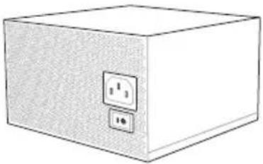
5. Témoins Q-Code
| Code Description | |
| 00 Not used | |
| 01 Power on. Reset type detection (soft/hard). | |
| 02 AP initialization before microcode loading | |
| 03 System Agent initialization before microcode loading | |
| 04 PCH initialization before microcode loading | |
| 06 Microcode loading | |
| 07 AP initialization after microcode loading | |
| 08 System Agent initialization after microcode loading | |
| 09 PCH initialization after microcode loading | |
| 0B Cache initialization | |
| 0C - 0D Reserved for future AMI SEC error codes | |
| 0E Microcode not found | |
| 0F Microcode not loaded | |
| 10 PEI Core is started | |
| 11 - 14 Pre-memory CPU initialization is started | |
| 15 - 18 Pre-memory System Agent initialization is started | |
| 19 - 1C Pre-memory PCH initialization is started | |
| 2B - 2F Memory initialization | |
| 30 Reserved for ASL (see ASL Status Codes section below) | |
| 31 Memory Installed | |
| 32 - 36 CPU post-memory initialization | |
| 37 - 3A Post-Memory System Agent initialization is started | |
| 3B - 3E Post-Memory PCH initialization is started | |
| 4F DXE IPL is started | |
| 50 - 53 | Memory initialization error. Invalid memory type or incompatible memory speed |
| 54 Unspecified memory initialization error | |
| 55 Memory not installed | |
| 56 Invalid CPU type or Speed | |
| 57 CPU mismatch | |
| 58 CPU self test failed or possible CPU cache error | |
| 59 CPU micro-code is not found or micro-code update is failed | |
| Code Description | |
| 10 PEI Core is | started |
| 11 – 14 Pre-memory CPU initialization is started | |
| 15 – 18 Pre-memory System Agent initialization is started | |
| 19 – 1C Pre-memory PCH initialization is started | |
| 2B – 2F Memory initialization | |
| 30 Reserved for ASL (see ASL Status Codes section below) | |
| 31 Memory Installed | |
| 32 – 36 CPU post-memory initialization | |
| 37 – 3A Post-Memory System Agent initialization is started | |
| 3B – 3E Post-Memory PCH initialization is started | |
| 4F DXE IPL is | started |
| 50 – 53 | Memory initialization error. Invalid memory type or incompatible memory speed |
| 54 Unspecified | memory initialization error |
| 55 Memory not installed | |
| 56 Invalid CPU type or Speed | |
| 57 CPU mismatch | |
| 58 CPU self test failed or possible CPU cache error | |
| 59 CPU micro-code is not found or micro-code update is failed | |
| 5A Internal CPU error | |
| 5B Reset PPI is not available | |
| 5C – 5F Reserved for future AMI error codes | |
| E0 S3 Resume is stared (S3 Resume PPI is called by the DXE IPL) | |
| E1 S3 Boot Script execution | |
| E2 Video repost | |
| E3 OS S3 wake vector call | |
| E4 – E7 Reserved for future AMI progress codes | |
| E8 S3 Resume Failed | |
| E9 S3 Resume PPI not Found | |
| EA S3 Resume Boot Script Error | |
| EB S3 OS Wake Error | |
| EC – EF Reserved for future AMI error codes | |
Code Description
F0 Recovery condition triggered by firmware (Auto recovery)
F1 Recovery condition triggered by user (Forced recovery)
F2 Recovery process started
F3 Recovery firmware image is found
F4 Recovery firmware image is loaded
F5 – F7 Reserved for future AMI progress codes
F8 Recovery PPI is not available
F9 Recovery capsule is not found
FA Invalid recovery capsule
FB - FF Reserved for future AMI error codes
60 DXE Core is started
61 NVRAM initialization
62 Installation of the PCH Runtime Services
63 – 67 CPU DXE initialization is started
68 PCI host bridge initialization
69 System Agent DXE initialization is started
6A System Agent DXE SMM initialization is started
6B - 6F System Agent DXE initialization (System Agent module specific)
70 PCH DXE initialization is started
71 PCH DXE SMM initialization is started
72 PCH devices initialization
73-77 PCH DXE Initialization (PCH module specific)
78 ACPI module initialization
79 CSM initialization
7A – 7F Reserved for future AMI DXE codes
90 Boot Device Selection (BDS) phase is started
91 Driver connecting is started
92 PCI Bus initialization is started
93 PCI Bus Hot Plug Controller Initialization
94 PCI Bus Enumeration
95 PCI Bus Request Resources
| Code Description | |
| 96 PCI Bus Assign Resources | |
| 97 Console Output devices connect | |
| 98 Console input devices connect | |
| 99 Super IO Initialization | |
| 9A USB initialization is started | |
| 9B USB Reset | |
| 9C USB Detect | |
| 9D USB Enable | |
| 9E – 9F Reserved for future AMI codes | |
| A0 IDE initialization is started | |
| A1 IDE Reset | |
| A2 IDE Detect | |
| A3 IDE Enable | |
| A4 SCSI initialization is started | |
| A5 SCSI Reset | |
| A6 SCSI Detect | |
| A7 SCSI Enable | |
| A8 Setup Verifying Password | |
| A9 Start of Setup | |
| AA Reserved for ASL (see ASL Status Codes section below) | |
| AB Setup Input Wait | |
| AC Reserved for ASL (see ASL Status Codes section below) | |
| AD Ready To Boot event | |
| AE Legacy Boot event | |
| AF Exit Boot Services event | |
| B0 Runtime Set Virtual Address MAP Begin | |
| B1 Runtime Set Virtual Address MAP End | |
| B2 Legacy Option ROM Initialization | |
| B3 System Reset | |
| B4 USB hot plug | |
| B5 PCI bus hot plug | |
| Code Description | |
| B6 Clean-up of NVRAM | |
| B7 Configuration Reset (reset of NVRAM settings) | |
| B8-BF Reserved for future AMI codes | |
| D0 CPU initialization error | |
| D1 System Agent initialization error | |
| D2 PCH initialization error | |
| D3 Some of the Architectural Protocols are not available | |
| D4 PCI resource allocation error. Out of Resources | |
| D5 No Space for Legacy Option ROM | |
| D6 No Console Output Devices are found | |
| D7 No Console Input Devices are found | |
| D8 Invalid password | |
| D9 Error loading Boot Option (LoadImage returned error) | |
| DA Boot Option is failed (StartImage returned error) | |
| DB Flash update is failed | |
| DC Reset protocol is not available |
| Code Description | |
| 0x01 System is entering S1 sleep state | |
| 0x02 System is entering S2 sleep state | |
| 0x03 System is entering S3 sleep state | |
| 0x04 System is entering S4 sleep state | |
| 0x05 System is entering S5 sleep state | |
| 0x10 System is waking up from the S1 sleep state | |
| 0x20 System is waking up from the S2 sleep state | |
| 0x30 System is waking up from the S3 sleep state | |
| 0x40 System is waking up from the S4 sleep state | |
| 0xAC System has transitioned into ACPI mode. Interrupt controller is in PIC mode. | |
| 0xAA System has transitioned into ACPI mode. Interrupt controller is in APIC mode. |
natural_image
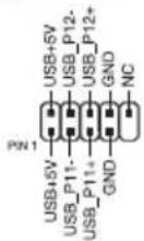
Line drawing of a USB cable connector with two ports and a separate port (no text or symbols)A USB1112
(4-pin CPU_FAN; 4-pin CPU_OPT; 4-pin CHA_FAN1A-3A; 4-pin CHA_FAN1B-3B)
(24-pin EATXPWR; 8-pin EATX12V_1, 4-pin EATX12V_2)
text_image
T_SENSOR1 PIN 1 GND SENSOR INnatural_image
Technical line drawing of a mechanical assembly with multiple components and a close-up of a tool tip (no text or symbols)
natural_image
Diagram of a computer tower with ventilation fan and rack-mounted unit (no text or labels)natural_image
Line drawing of a computer monitor with ventilation grille and keyboard (no text or symbols)natural_image
Technical line drawing of a computer motherboard with CPU socket and screwdriver (no text or symbols)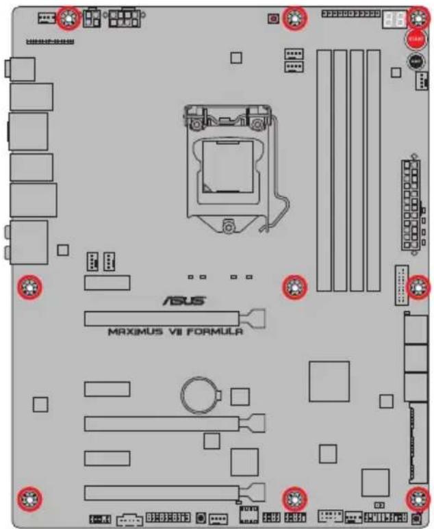
text_image
ASUS MAXIMUS VII FORMULR
natural_image
Hand holding a device with a red X mark, no visible text or symbols
text_image
1 A B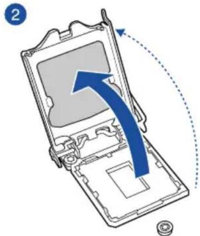
text_image
2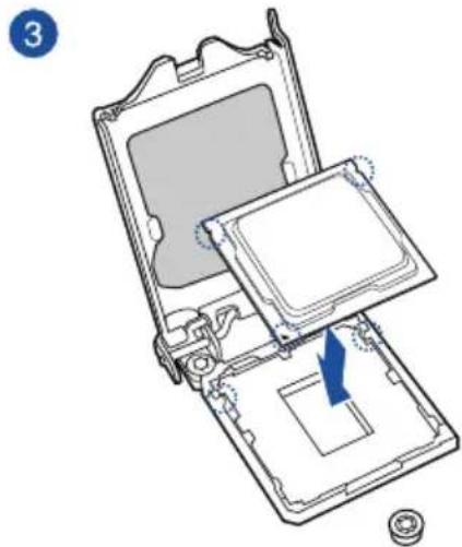
natural_image
Diagram of a computer case with an open lid and internal components, showing a blue arrow indicating a specific area (no text or symbols present)
text_image
4 A C B
natural_image
Diagram of a computer processor casing with an arrow indicating a component being removed (no text or symbols present)natural_image
Technical line drawing of a mechanical assembly with a tool and component (no text or symbols)
natural_image
Technical line drawing of a CPU fan with cooling fins and heatsink, showing mechanical assembly (no text or symbols)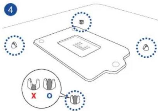
text_image
4 X Onatural_image
Diagram of a CPU fan with blue arrows indicating rotation or cooling mechanism (no text or symbols present)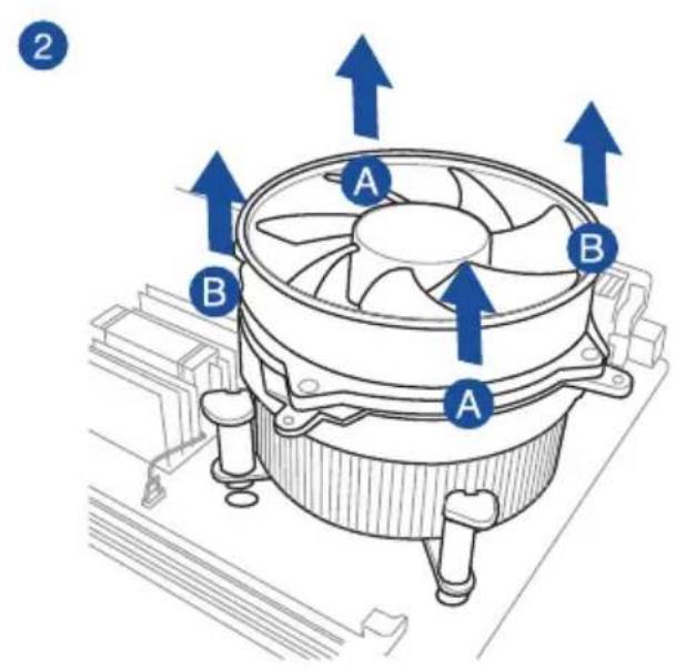
text_image
2 A B A Bnatural_image
Diagram of a computer RAM module with labeled components A and B, showing internal structure and directional arrows (no text or symbols beyond labels)natural_image
Diagram of an internal hard drive connected to a terminal connector via USB cable (no text or symbols)
natural_image
Diagram of a hard disk connected to two USB connectors with blue arrows indicating connection (no text or symbols present)2

natural_image
Diagram showing two connected devices with a cable and connector, no text or symbols presentnatural_image
Technical diagram of a computer monitor internal structure with no visible text or symbolsnatural_image
3D diagram of a device with labeled components and wiring, no readable text or symbols present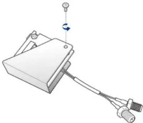
natural_image
Mechanical component diagram showing a clamp or bracket with attached cable and connector (no text or symbols)
natural_image
Mechanical assembly diagram showing a clamping device with a blue arrow indicating direction (no text or symbols)
natural_image
Mechanical device with attached cable and sensor, showing a rotating arm (no text or symbols)natural_image
Mechanical assembly diagram showing a component with mounting holes and wiring, no visible text or symbolsInstaller la carte mPCIe Combo III
natural_image
Technical illustration of a mechanical device with threaded connectors and a blue arrow indicating direction (no text or symbols)natural_image
Diagram of an electronic device with a blue arrow pointing to a component, no text or symbols present
natural_image
Diagram of a mechanical component with arrows indicating rotation and movement, no text or symbols present
natural_image
Technical line drawing of a device panel with connectors and buttons, no visible text or symbolstext_image
washer bolt washer boltnatural_image
Diagram showing a device with cable routing and a close-up view of internal components (no text or symbols)natural_image
Technical line drawing of an electronic device panel with ports and connectors (no text or symbols)text_image
Diagram showing various server rack and control panel configurations with labeled icons for each component.natural_image
Illustration of a microphone connected to a display unit with colored probes (no text or symbols)Assistant EZ Tuning (F11)
text_image
REPUBLIC OF GAMERS UEFI BIOS Utility - Advanced Mode 03/02/2009 22:38 English MyFavorite(F3) Qtan Control(F6) EZ Tuning Wizard(F11) Quick Note(F9) Hot Keys My Favorites Extreme Tweaker Main Advanced Monitor Boot Tool Exit LNZ Mode Disabled Target CPU Frequency: 2400MHz Target DRAM Frequency: 1333MHz Target Cache Frequency: 2400MHz Target DMI/PEG Frequency: 100MHz Target CPU Graphics Frequency: 1050MHz Ai Overclock Tuner Auto ASUS MultiCore Enhancement Auto CPU Core Ratio Sync All Cores 1-Core Ratio Limit Auto 2-Core Ratio Limit Auto Min. CPU Cache Ratio Auto Max. CPU Cache Ratio Auto [Manual]: When the manual mode is selected, the BCLK(base clock) Frequency can be assigned manually. [XMP]: When the XMP(extreme memory profile) mode is selected, the BCLK frequency and memory parameters will be optimized. automatically. Last Modified EzMode(F7) Hardware Monitor CPU Frequency Temperature 2400 MHz 66°C BCLK Vcore 100.0 MHz 0.816 V Ratio 24x Memory Frequency Voltage 1333 MHz 1.501 V Capacity 2048 MB Voltage +12V +5V 12.096 V 5.080 V +3.3V 3.312 V Version 2.16.1240. Copyright (C) 2014 American Megatrends, Inc.BCLK Frequency (Fréquence BCLK) [100]
CPU Core Ratio (Ratio CPU) [Sync All Cores]
[DDR3-1400MHz] [DDR3-1600MHz] [DDR3-1800MHz] [DDR3-1866MHz] [DDR3-2000MHz]
[DDR3-2133MHz] [DDR3-2200MHz] [DDR3-2400MHz] [DDR3-2600MHz] [DDR3-2666MHz]
[DDR3-2800MHz] [DDR3-2933MHz] [DDR3-3000MHz] [DDR3-3200MHz] [DDR3-3400MHz]
Xtreme Tweaking [Disabled]
[Mode 2] Overclocking et performances.
Primary Timings
DRAM CAS# Latency [Auto]
Options de configuration : [Auto] [1] - [31]
DRAM CAS# Latency [Auto]
Options de configuration : [Auto] [1] - [31]
DRAM RAS# to CAS# Delay [Auto]
Options de configuration : [Auto] [1] - [31]
DRAM RAS# PRE Time [Auto]
Options de configuration : [Auto] [1] - [31]
DRAM RAS# ACT Time [Auto]
Options de configuration : [Auto] [1] - [63]
DRAM Command Rate [Auto]
Options de configuration : [Auto] [1] - [2]
Secondary Timings
DRAM RAS# to RAS# Delay [Auto]
Options de configuration : [Auto] [1] - [15]
DRAM REF Cycle Time [Auto]
Options de configuration : [Auto] [1] - [511]
DRAM Refresh Interval [Auto]
Options de configuration : [Auto] [1] - [65535]
DRAM WRITE Recovery Time [Auto]
Options de configuration : [Auto] [1] - [16]
DRAM READ to PRE Time [Auto]
Options de configuration : [Auto] [1] - [15]
DRAM FOUR ACT WIN Time [Auto]
Options de configuration : [Auto] [1] - [255]
DRAM WRITE to READ Delay [Auto]
Options de configuration : [Auto] [1] – [15]
DRAM CKE Minimum Pulse Width [Auto]
Options de configuration : [Auto] [1] - [15]
DRAM CAS# Write Latency [Auto]
Options de configuration : [Auto] [1] - [31]
RTL IOL control
DRAM RTL Initial Value [Auto]
Options de configuration : [Auto] [1] - [63]
DRAM RTL (CHA_R0D0) [Auto]
Options de configuration : [Auto] [1] - [63]
DRAM RTL (CHA_R0D1) [Auto]
Options de configuration : [Auto] [1] - [63]
DRAM RTL (CHA_R1D0) [Auto]
Options de configuration : [Auto] [1] - [63]
DRAM RTL (CHA_R1D1) [Auto]
Options de configuration : [Auto] [1] - [63]
DRAM RTL (CHB_R0D0) [Auto]
Options de configuration : [Auto] [1] - [63]
DRAM RTL (CHB_R0D1) [Auto]
Options de configuration : [Auto] [1] - [63]
DRAM RTL (CHB_R1D0) [Auto]
Options de configuration : [Auto] [1] - [63]
DRAM RTL (CHB_R1D1) [Auto]
Options de configuration : [Auto] [1] - [63]
DRAM IO-L (CHA_R0D0) [Auto]
Options de configuration : [Auto] [1] - [15]
DRAM IO-L (CHA_R0D1) [Auto]
Options de configuration : [Auto] [1] - [15]
DRAM IO-L (CHA_R1D0) [Auto]
Options de configuration : [Auto] [1] - [15]
DRAM IO-L (CHA_R1D1) [Auto]
Options de configuration : [Auto] [1] - [15]
DRAM IO-L (CHB_R0D1) [Auto]
Options de configuration : [Auto] [1] - [15]
DRAM IO-L (CHB_R1D0) [Auto]
Options de configuration : [Auto] [1] - [15]
DRAM IO-L (CHB_R1D1) [Auto]
Options de configuration : [Auto] [1] - [15]
Third Timings
tRDRD [Auto]
Options de configuration : [Auto] [1] - [7]
tRDRD_dr [Auto]
Options de configuration : [Auto] [1] - [15]
tRDRD_dd [Auto]
Options de configuration : [Auto] [1] - [15]
tWRRD [Auto]
Options de configuration : [Auto] [1] - [63]
tWRRD_dr [Auto]
Options de configuration : [Auto] [1] - [15]
tWRRD_dd [Auto]
Options de configuration : [Auto] [1] - [15]
tWRWR [Auto]
Options de configuration : [Auto] [1] - [7]
tWRWR_dr [Auto]
Options de configuration : [Auto] [1] - [15]
tWRWR_dd [Auto]
Options de configuration : [Auto] [1] - [15]
Dec_WRD [Auto]
Options de configuration : [Auto] [0] [1]
tRDWR [Auto]
Options de configuration : [Auto] [1] - [31]
tRDWR_dr [Auto]
Options de configuration : [Auto] [1] - [31]
tRDWR_dd [Auto]
Options de configuration : [Auto] [1] - [31]
MISC
MRC Fast Boot [Auto]
Options de configuration : [Auto] [Enabled] [Disabled]
DRAM CLK Period [Auto]
Options de configuration : [Auto] [1] - [14]
Channel A DIMM Control [Enable Bot...]
Options de configuration : [Enable Both DIMMS] [Disable DIMM0] [Disable DIMM1]
[Disable Both DIMMS]
Channel B DIMM Control [Enable Bot...]
Options de configuration : [Enable Both DIMMS] [Disable DIMM0] [Disable DIMM1]
[Disable Both DIMMS]
Scrambler Setting [Optimized ...]
Options de configuration : [Optimized (ASUS)] [Default (MRC)]
Enabling these items helps overclocking.
Options de configuration : [Auto] [Enabled] [Disabled]
DRAM Additional Training [Auto]
Options de configuration : [Auto] [Enabled] [Disabled]
Skew Control
Transmitter Falling Slope [Auto]
Options de configuration : [Auto] [0] - [31]
Transmitter Control Time [Auto]
Options de configuration : [Auto] [0] - [31]
Receiver Rising Slope [Auto]
Options de configuration : [Auto] [0] - [31]
Receiver Falling Slope [Auto]
Options de configuration : [Auto] [0] - [31]
Receiver Control Time [Auto]
Options de configuration : [Auto] [0] - [31]
GPU.DIMM Post (Infos POST GPU)
External DIGI+ Power Control

CPU VRM Switching Frequency
CPU Power Duty Control [T.Probe]
Termination Anti-Aliasing [Auto]
Options de configuration : [Auto] [Disabled] [Enabled]
Initial PLL Termination Voltage [Auto]
Options de configuration : [Auto] [0.0000] - [3.0000]
PLL Termination Reset Voltage [Auto]
Options de configuration : [Auto] [0.0000] - [3.0000]
Eventual PLL Termination Voltage [Auto]
Options de configuration : [Auto] [0.0000] - [3.0000]
PCH ICC Voltage [Auto]
Options de configuration : [Auto] [Enabled] [Disabled]
Clock Crossing Boot Voltage [Auto]
Options de configuration : [Auto] [0.1000] - [1.9000]
Clock Crossing Reset Voltage [Auto]
Options de configuration : [Auto] [0.1000] - [1.9000]
Clock Crossing Voltage [Auto]
Options de configuration : [Auto] [0.1000] - [1.9000]
Internal CPU Power Management (Gestion d'alimentation interne du CPU)
Short Duration Package Power Limit [Auto]
CPU Integrated VR Current Limit [Auto]
CPU Internal Power Switching Frequency
CPU Internal Power Saving Control
Power Saving Level 1 Threshold
Power Saving Level 2 Threshold
Power Saving Level 3 Threshold
CPU Core Voltage Override
Additional Turbo Mode CPU Graphics Voltage (Tension additionnelles) [Auto]
SVID Support (Support SVID) [Auto]
BCLK Recovery (Restauration BCLK) [Enabled]
3.5 Menu Main (Principal)
text_image
REPUBLIC OF GAMERS UEFI BIOS Utility - Advanced Mode 03/16/2014 01:33 English MyFavorite(F3) Qfan Control(F6) EZ Tuning Wizard(F11) Quick Note(F9) HotKeys My Favorites Extreme Tweaker Main Advanced Monitor Boot Tool Exit Hardware Monitor CPU Frequency Temperature 3100 MHz 80°C 8CLK Utoro 100.0 MHz 0.928 V Ratio 31s Memory Frequency Voltage 1600 MHz 1.501 V Password Description If ONLY the Administrator's password is set, then this only limits access to Setup and is only asked for when entering Setup. If ONLY the User's password is set, then this is a power on password and must be entered to boot or enter Setup. In Setup the User will have Administrator rights. The password must be 3 to 20 characters long. Administrator Password Not Installed User Password Not Installed Administrator Password User Password
text_image
REPUBLIC OF GAMERS UEFI BIOS Utility - Advanced Mode 03/02/2009 22:43 English MyFavorite(F3) Qtan Control(F6) EZ Tuning Wizard(F11) Quick Note(F9) Hot Keys Monday My Favorites Extreme Tweaker Main Advanced Monitor Boot Tool Exit Hardware Monitor Advanced/CPU Configuration CPU Configuration Intel(R) Celeron(R) CPU G1E20T @ 2.40GHz CPU Signature 306c3 Microcode Patch 17 Max CPU Speed 2400 MHz Min CPU Speed 800 MHz CPU Speed 2400 MHz Processor Cores 2 Intel HT Technology Not Supported Intel VT-x Technology Supported Intel SMK Technology Not Supported 64-bit Supported EST Technology Supported CPU C3 state Supported CPU C6 state Supported Last Modified EzMode(F7) Version 2.16.1240. Copyright (C) 2014 American Megatrends, Inc.Intel Adaptive Thermal Monitor (Surveillance thermique adaptive) [Enabled]
Adjacent Cache Line Prefetcher [Enabled]
[Enabled] Active la fonction Adjacent Cache Line Prefetcher.
[Disabled] Désactive cette option.
Boot Performance Mode (Mode de performance au démarrage) [Max Non-Turbo Performance]
C6 Latency (Latence C6) [Short]
C7 Latency (Latence C7) [Long]
Package C State Support [Auto]
PCI Express Configuration (Configuration PCI Express)
Entry on S3 RTC Wake [Enabled]
Options de configuration : [Disable] [Enable]
Entry After [Immediately]
Options de configuration : [Immediately] [1 minute] [2 minutes] [5 minutes] [10 minutes] [15 minutes] [30 minutes] [1 hour] [2 hours]
Active Page Threshold Support [Enabled]
Active Memory Threshold [0]
Intel (R) Smart Connect Technology
(Technologie Intel Smart Connect) [Disabled]
Aggressive LPM Support (Support LPM aggressif) [Auto]
Options de configuration : [Disabled] [Enabled]
SATA6G\_1 (Red) - SATA6G\_6 (Red)
CPU Graphics Multi-Monitor (Multi-affichage iGPU) [Disabled]
Memory Scrambler [Enabled]
Options de configuration : [Enabled] [Disabled]
3.6.5 USB Configuration (Configuration USB)
text_image
REPUBLIC OF GAMERS UEFI BIOS Utility - Advanced Mode 03/02/2009 22:46 English MyFavorite(F3) Qfan Control(F6) EZ Tuning Wizard(F11) Quick Note(F9) Hot Keys Monday My Favorites Extreme Tweaker Main Advanced Monitor Boot Tool Exit Advanced\USB Configuration USB Configuration USB Devices: 1 Keyboard, 1 Mouse, 2 Hubs Legacy USB Support Enabled Intel xHCI Mode Smart Auto EHCI Hand-off Disabled USB Single Port Control Hardware Monitor CPU Frequency Temperature 2400 MHz 66°C BCLK Vcore 100.0 MHz 0.816 V Ratio 24x Memory Frequency Voltage 1333 MHz 1.501 V
ASPM Support (Support ASPM) [Disabled]
Options de configuration : [Disabled] [Auto] [ASPM L0s] [ASPM L1] [ASPM L0sL1]
SA - PCI Express
ASPM Support (Support ASPM) [Disabled]
3.6.7 Onboard Devices Configuration
ASPM Support (Support ASPM) [Disabled]
Options de configuration : [Disabled] [Enabled]
Ipv4 /Ipv6 PXE Support [Enable]
Options de configuration : [Disabled] [Enabled]
3.6.10 ROG Effects (Effets ROG)
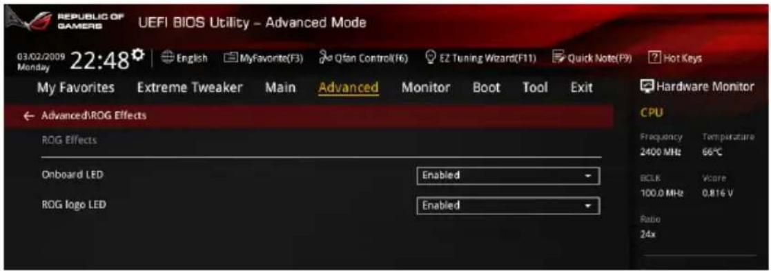
text_image
REPUBLIC OF GAMERS UEFI BIOS Utility - Advanced Mode 03/02/2009 22:48 English MyFavorite(F3) Qtan Control(F6) EZ Tuning Wizard(F11) Quick Note(F9) Hot Keys My Favorites Extreme Tweaker Main Advanced Monitor Boot Tool Exit Advanced/ROG Effects ROG Effects Onboard LED Enabled ROG logo LED Enabled Hardware Monitor CPU Frequency Temperature 2400 MHz 66°C BCLK Vcore 100.0 MHz 0.816 V Ratio 24xtext_image
REPUBLIC OF GAMERS UEFI BIOS Utility - Advanced Mode 03/02/2009 22:40 Monday English MyFavorite(F3) Qfan Control(F6) EZ Tuning Wizard(F11) Quick Note(P9) Hot Keys My Favorites Extreme Tweaker Main Advanced Monitor Boot Tool Exit > Qfan Tuning Anti-Surge Support Enabled > Voltage Monitor > Temperature Monitor > Fan Speed Monitor > Fan Speed Control Hardware Monitor CPU Frequency Temperature 2400 MHz 66°C 8CLK Vccorr 100.0 MHz 0.816 V Ratio 24x Memory Frequency UpdateQfan Tuning
Anti Surge Support (Support anti-surtensions) [Enabled]
CPU Core 0-3 Voltage; CPU Cache Voltage; CPU System Agent Voltage; CPU Analog I/O Voltage; CPU Digital I/O Voltage; CPU Input Voltage; DRAM Voltage; PCH Voltage; 3.3V Voltage; 5V Voltage; 12V Voltage
CPU Temperature; MB Temperature; VRM Temperature; SENSOR1 Temperature [xxx°C/xxx°F] or [N/A]
CPU FAN Speed; CPU Optional Fan Speed; Chassis FAN 1-3 A/B Speed
CPU Fan Speed Low Limit
CPU Fan Max. Duty Cycle
CPU Fan Middle Duty Cycle(%)
Chassis Fan 1/3 Q-Fan Source
Chassis Fan Middle Temperature
CPU Fan Middle Duty Cycle(%)
text_image
REPUBLIC OF GAMERS UEFI BIOS Utility - Advanced Mode 03/02/2009 22:40 English MyFavorite(F3) Qfan Control(F6) EZ Tuning Wizard(F11) Quick Note(F8) Hot Keys My Favorites Extreme Tweaker Main Advanced Monitor Boot Tool Exit Fast Boot Enabled SATA Support All Devices USB Support Partial Initialization PS/2 Keyboard and Mouse Support Auto Network Stack Driver Support Disabled Next Boot after AC Power Loss Normal Boot DirectKey (DRCT) Enabled Boot Logo Display Disabled POST Report 5 sec Boot up NumLock State Enabled Walt For 'F1' If Error Enabled Enabled/Disabled boot with initialization of a minimal set of devices required to launch active boot option. Has no effect for BBS boot options. Hardware Monitor CPU Frequency Temperature 2400 MHz 66°C 9CLK Vcore 100.0 MHz 0.816 V Ratio 24x Memory Frequency Voltage 1.333 MHz 1.498 V Capacity 2048 MB Voltage -12V +5V 12.096 V 5.040 V +3.3V 3.312 VSATA Support (Support SATA) [All Devices]
USB Support (Support USB) [Partial Initialization]
Next boot after AC Power Loss
DirectKey (DRCT) [Enabled]
CSM (Compatibility Support Module)
Boot from Network Devices [Legacy OpRom first]
Configuration option: [Legacy OpROM first] [UEFI driver first] [Ignore]
Boot from Storage Devices [Legacy OpRom first]
Configuration option: [Both, Legacy OpROM first] [Both, UEFI first] [Legacy OpROM first] [UEFI driver first] [Ignore]
Boot from PCI-E/PCI Expansion Devices [Legacy OpRom first]
Configuration option: [Legacy OpROM first] [UEFI driver first]
Append dbx from file
text_image
REPUBLIC OF GAINING UEFI BIOS Utility - Secure Erase BDO 330 Secure Erase 330 speeds may lower over time as with any storage medium due to data processing, secure erase completely and safely clean your 330, reducing it to factory performance levels. WARNING: This process will take a few minutes. Do not turn off the system during the process. Part # 330 Base Status Total capacity F1 KONZITIM 24108532906 Result 240-068 Erase Lecteur(s) SSD disponible(s) Cliquez pour démarrer Secure Erase
text_image
REPUBLIC OF GAMERS UEFI BIOS Utility - Advanced Mode 03/02/2009 22:56 English MyFavorite(F3) Qfan Control(F6) EZ Tuning Wizard(F11) Quick Note(F9) Hot Keys My Favorites Extreme Tweaker Main Advanced Monitor Boot Tool Exit ToolNASUS Overclocking Profile Overclocking Profile Profile 1 status: Not assigned Profile 2 status: Not assigned Profile 3 status: Not assigned Profile 4 status: Not assigned Profile 5 status: Not assigned Profile 6 status: Not assigned Profile 7 status: Not assigned Profile 8 status: Not assigned Load Profile The last loaded profile: N/A Load from Profile 1 Profile Setting Profile Name Hardware Monitor CPU Frequency Temperature 2400 MHz 66°C BCLK Vccore 100.0 MHz 0.816 V Ratio 24k Memory Frequency Voltage 1333 MHz 1.504 V Capacity 2048 MB Voltage +12V +5V 12.095 V 5,080 V
BCLK Frequency (Fréquence BCLK) [Auto]
Load from profile (Charger un profil)
Launch EFI Shell from USB drives
ISOLINUX 3.20 2006-08-26 Copyright (C) 1994-2005 H. Peter Anvin A Bootable DVD/CD is detected. Press ENTER to boot from the DVD/CD. If no key is pressed within 5 seconds, the system will boot next priority device automatically. boot:
text_image
Are you sure you want to update the BIOS? Yes No
DECLARATION OF CONFORMITY
Per FCC Part 2 Section 2. 1077(a)

Responsible Party Name: Asus Computer International
Address: 800 Corporate Way, Fremont, CA 94539.
Phone/Fax No: (510)739-3777/(510)608-4555
hereby declares that the product
Product Name : Motherboard
Model Number : MAXIMUS VII FORMULA
Conforms to the following specifications:
☒ FCC Part 15, Subpart B, Unintentional Radiators
Supplementary Information:
This device complies with part 15 of the FCC Rules. Operation is subject to the following two conditions: (1) This device may not cause harmful interference, and (2) this device must accept any interference received, including interference that may cause undesired operation.
Representative Person's Name: Steve Chang / President

Signature :
[Non-Text]
Ver. 140331

EC Declaration of Conformity
We, the undersigned,
| Manufacturer: | ASUSTeK COMPUTER INC. |
| Address: | 4F, No. 150, LI-TE Rd., PEITOU, TAIPEI 112, TAIWAN |
| Authorized representative in Europe: | ASUS COMPUTER GmbH |
| Address, City: | HARKORT STR. 21-23, 40880 RATINGEN |
| Country: | GERMANY |
| Product name : Motherboard | |
| Model name : MAXIMUS VII FORMULA |
conform with the essential requirements of the following directives:
2004/108/EC-EMC Directive
EN 55022:2010+AC:2011 EN 61000-3-2:2006-A2:2009 EN 55013:2001+A1:2003+A2
1999/5/EC-R&TTE Directive
| EN 300 328 V1.7.1(2006-10) | EN 301 489-1 V1.9.2(2011-09) |
| EN 300 440-1 V1.6.1(2010-08) | EN 301 489 3 V1.4.1(2002-08) |
| EN 300 440-2 V1.4.1(2010-08) | EN 301 489-4 V1.4.1(2009-05) |
| EN 301 511 V9.0.2(2003-03) | EN 301 489-7 V1.3.1(2005-11) |
| EN 301 908-1 V5.2.1(2011-05) | EN 301 489-9 V1.4.1(2007-11) |
| EN 301 908-2 V5.2.1(2011-07) | EN 301 489-17 V2.2.1(2012-09) |
| EN 301 893 V1.6.1(2011-11) | EN 301 489-24 V1.5.1(2010-09) |
| EN 302 544-2 V1.1.1(2009-01) | EN 302 326-2 V1.2.2(2007-06) |
| EN 302 623 V1.1.1(2009-01) | EN 302 326-3 V1.3.1(2007-09) |
| EN 50360:2001 | EN 301 357-2 V1.4.1(2008-11) |
| EN 62479:2010 | EN 302 291-1 V1.1.1(2005-07) |
| EN 50385:2002 | EN 302 291-2 V1.1.1(2005-07) |
| EN 62311:2008 |
2006/95/EC-LVD Directive
EN 60065:2002 / A12:2011
2009/125/EC-ErP Directive
| ☐ Regulation (EC) No. 1275/2008 | ☐ Regulation (EC) No. 278/2009 |
| ☐ Regulation (EC) No. 642/2009 | ☐ Regulation (EC) No. 617/2013 |
2011/65/EU-RoHS Directive
CE marking

(EC conformity marking)
Position: CEO
Name: Jerry Shen

Year to begin affixing CE marking: 2014
Declaration Date: 04/06/2014
(EC conformity marking)
□ SE marking
Position
Name :
