SG-F77W - Speaker Fusion - Free user manual and instructions
Find the device manual for free SG-F77W Fusion in PDF.
| Product type | Marine audio subwoofer enclosure |
| Brand and model | Fusion SG-F77W |
| Maximum power | 450 W |
| RMS power | 250 W |
| Sensitivity (1 W/1 m) | 88 dB |
| Frequency response (+3 dB) | 30 Hz to 2 kHz |
| Impedance | 4 ohms |
| Mounting diameter (cutout) | 223 mm (8.78 in) |
| Minimum mounting depth | 130 mm (5.125 in) |
| Protection rating (front face) | IP65 (water and dust resistant) |
| LED supply voltage (sports model) | 10.8 to 16 V DC |
| LED current at 14.4 V DC | 150 mA |
| Operating temperature range | 0 to 50 °C |
| Storage temperature range | -20 to 70 °C |
| Compass safe distance | 520 cm (204.724 in) |
| Package contents | Subwoofer enclosure, 6 mounting screws, mounting template, grille (classic), LED cable (sports), Allen key (sports) |
| Tools required for installation | Drill, drill bit, Phillips screwdriver, wire stripper, crimping tool, insulating tape, saw or knife |
| Maintenance and cleaning | Clean with a damp cloth and fresh water; use mild detergent for salt residues; avoid abrasive cleaners |
| Warranty | Limited 3-year warranty (True-Marine products) |
| Product registration | Online at www.fusionentertainment.com |
Frequently Asked Questions - SG-F77W Fusion
User questions about SG-F77W Fusion
0 question about this device. Answer the ones you know or ask your own.
Ask a new question about this device
Download the instructions for your Speaker in PDF format for free! Find your manual SG-F77W - Fusion and take your electronic device back in hand. On this page are published all the documents necessary for the use of your device. SG-F77W by Fusion.
USER MANUAL SG-F77W Fusion
Signature Series Subwoofer Installation Instructions ....2
Garmin ^® , the Garmin logo, and the Fusion ^™ logo are trademarks of Garmin Ltd. or its subsidiaries, registered in the USA and other countries. Fusion and True-Marine ^™ are trademarks of Garmin Ltd. or its subsidiaries. These trademarks may not be used without the express permission of Garmin.
Signature Series Subwoofer Installation Instructions
Important Safety Information
WARNING
Failure to follow these warnings and cautions could result in personal injury, damage to the vessel, or poor product performance.
See the Important Safety and Product Information guide in the product box for product warnings and other important information.
This device must be installed according to these instructions.
Disconnect the vessel's power supply before beginning to install this product.
CAUTION
Audio systems can produce sound pressure levels exceeding 135 dB. Continuous exposure to sound pressure levels over 100 dB may cause permanent hearing loss. The volume is typically too loud if you cannot hear people speaking around you. Limit the amount of time you listen at high volume. If you experience ringing in your ears or muffled speech, stop listening and have your hearing checked.
Always wear safety goggles, ear protection, and a dust mask when drilling, cutting, or sanding.
NOTICE
When drilling or cutting, always check what is on the opposite side of the surface.
It is strongly recommended that you have your audio system installed by a professional installer to ensure optimum performance.
You must read all installation instructions before beginning the installation. If you experience difficulty during the installation, go to www.fusionentertainment.com for product support.
After installing the subwoofer, you should run the subwoofer at low to medium volumes for the first few hours of use. This helps to improve the overall sound by gradually loosening up the moving components of the subwoofer, such as the cone, spider, and surround
What's In the Box
- 1 subwoofer
- 6 Phillips stainless steel, 4.8 mm x 50 mm (10 gauge x 2 in.) mounting screws
- Mounting template
- Grille (Classic models only)
- 1 tinned LED connection cable (6 m) (Sports models only)
• Hex key (Sports models only)
Tools Needed
- Electric drill
- Drill bit (size varies based on surface material)
- Phillips screwdriver
- Wire strippers
- Crimping tool
- Electrical tape
- Appropriate saw or utility knife to cut surface material
- Suitable gauge speaker wire for the length required
NOTE: For customized installations, additional tools and materials may be needed.
Mounting Considerations
Selecting the correct mounting location is critical to optimize the performance of the audio system. Fusion™ subwoofer is designed to perform in the widest possible range of mounting locations, but the more you plan the installation, the better the subwoofer's sound will be.
- The audio system must be turned off before making any connections. Failure to do so could result in permanent damage to the audio system.
- You should protect all terminals and connections from grounding and from each other. Failure to do so could result in permanent damage to the audio system and voids the product warranty.
- You should protect the wires from sharp objects and always use rubber grommets when wiring through panels.
- The mounting location must avoid potential obstacles, such as fuel and hydraulic lines and wiring.
- The mounting location must provide sufficient clearance for the mounting depth of the subwoofer as specified in the side view drawings and the specifications.
- When possible, the area behind each subwoofer should be enclosed.
- To avoid interference with a magnetic compass, the subwoofer should not be installed closer to a compass than the compass-safe distance value listed in the product specifications.
- You should select a flat mounting surface for the best seal.
- For better bass performance, the subwoofer should be mounted in an area that provides just enough room behind the subwoofer. Too small an area restricts bass, and too large an area compromises bass performance. Placing a subwoofer close to an open area produces the least bass.
- When a subwoofer is not exposed to the outside environment, a better bass performance can be achieved using an enclosure that has a ported design. See the optimum enclosure design recommendations. Those recommendations specify volume only, and for the ported option, an optimum port size and length are also provided.
- If you intend to mount the subwoofer outside the boat, follow these considerations.
- When mounted correctly, the subwoofer is rated IP65 for protection in the harsh marine environment from the front of the subwoofer. Water exposure and damage to the rear of the subwoofer voids the warranty.
- The subwoofer must be mounted in a location well above the waterline, where it is not submerged.
• The subwoofer must be mounted in a location where it cannot be damaged by docks, pilings, or other pieces of equipment.
The subwoofer should be mounted in a sealed enclosure, especially if it is exposed to wash down. A port or vent may allow water to collect in the enclosure and damage the subwoofer.
Mounting the Subwoofer
Before mounting the subwoofer, you must choose a location where there is enough clearance behind the mounting surface. Refer to the side view drawing and the specifications for clearance information.
Before mounting the subwoofer, you must choose a location following the mounting considerations.
If you are replacing a Fusion MS-SW10 10" subwoofer with the Signature Series Classic model 10" subwoofer, see Replacing a Fusion MS-SW10 10" Subwoofer.
1 Route the wires from the source to the mounting location, away from sources of electrical interference.
2 Trim the template and make sure it fits in the selected location.
3 Orient the template with the Fusion logo at the bottom of the template.
4 Secure the template to the selected location.
5 Using a drill bit appropriate for the mounting surface, drill a hole inside the dashed line on the template to prepare the mounting surface for cutting.
6 Using a jigsaw or rotary tool, cut the mounting surface along the inside of the line on the template.
7 Place the subwoofer in the cutout to test the fit.
8 If necessary, use a file and sandpaper to refine the size of the cutout.
9 After the subwoofer fits correctly in the cutout, ensure the mounting holes on the subwoofer line up with the pilot holes on the template.
10 If the mounting holes do not line up, mark the new hole locations.
11 Using an appropriately sized drill bit for the mounting surface and screw type, drill the holes.
12 Remove the template from the mounting surface.
13 Connect the subwoofer wires while observing polarity. For more information on wiring polarity, see Subwoofer Sound Optimization
14 If necessary, connect the LED wires to the Sports model subwoofer (see Sports Model LED Wiring).
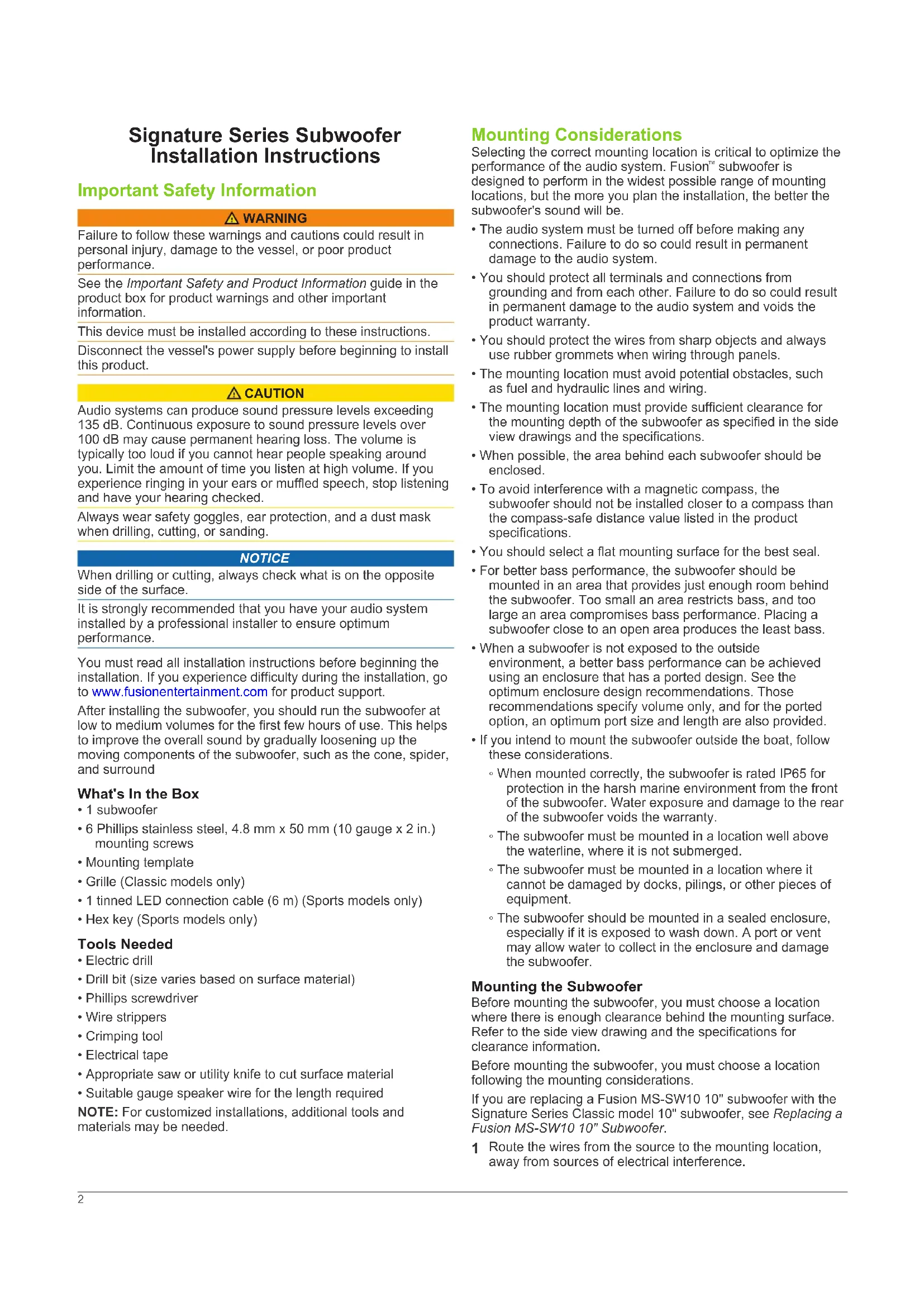
15 Place the subwoofer in the cutout.
natural_image
Technical line drawing of a mechanical component with multiple blades and a central circular housing (no text or symbols)16 Secure the subwoofer to the mounting surface using the included screws.
NOTE: Do not over tighten the screws, especially if the mounting surface is not flat.
For the Classic model subwoofer, you should attach the grille to the front (see Attaching the grille to the Classic Model Subwoofer).
Replacing a Fusion MS-SW10 10" Subwoofer
You can replace a Fusion MS-SW10 10" subwoofer with the Signature Series Classic model 10" subwoofer. You do not need to cut or drill new holes.
1 Remove the MS-SW10 from the mounting surface.
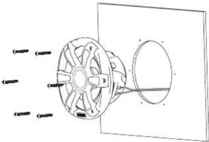
2 Remove each oblong washer from the front of the subwoofer.
3 Turn each washer ① so the hole is oriented toward the center of the subwoofer.
4 Replace each washer.
natural_image
Pure technical line drawing of a mechanical component with no text or symbols5 Continue mounting the subwoofer, starting at step 13 in Mounting the Subwoofer.
Sports Model LED Wiring
Connecting the LED Wires to the Sports Model Subwoofer
NOTE: This feature is available only on the Sports model subwoofer.
You can control the color of the LEDs by the polarity of the LED wires.
1 Using the hex key, loosen the screws on the wiring terminals on the back of the subwoofer.
2 Connect the black and red wires to the terminal according to the preferred LED color.
| Blue LED Black to negative (-)Red to positive (+) |
| White LED Black to positive (+)Red to negative (-) |
3 Using the hex key, tighten the screws on the wiring terminals.
Connecting the Sports Model Subwoofer LED Wires to Power
NOTE: This feature is available only on the Sports model subwoofer.
All 12 Vdc wiring to the LEDs must be fused at the power-source end of your cable using a 3 A fuse. The red power (+) wire should be connected to a 12 Vdc source through an isolator switch or circuit breaker to turn the LEDs on and off. You can use the same isolator or circuit breaker controlling the supply to your stereo, which allows you to turn the LEDs and the stereo on and off at the same time.
If it is necessary to extend the red and black wires, you should use 20 AWG (0.5 mm ^4 ) or thicker wire.
1 Route the red power (+) and black ground (-) wires to the battery and subwoofer.
2 Connect the black wire to the negative (-) battery terminal.
3 Connect the red wire to the positive (+) battery terminal through a 3 A fuse and isolator switch or circuit breaker.
Attaching the grille to the Classic Model Subwoofer
NOTE: This feature is available only on the Classic model subwoofer.
1 With the subwoofer mounted, hold the grille with the Fusion logo at the bottom, at the 6 o'clock position.
2 Turn the grille counter-clockwise about 10°, so the Fusion logo is at the 5 o'clock position.
3 Place the grille on the rim of the subwoofer.
4 Twist the grille clockwise to secure it.
Subwoofer Sound Optimization
While installing the subwoofer, you can ensure the sound from the subwoofer is optimized by running the subwoofer out of phase. You can switch the positive and negative wires on the subwoofer to run them out of phase.
Running the subwoofer out of phase from the speakers allows you to hear if the perception of bass is more from the location of
the subwoofer or speakers. If running the subwoofer out of phase gives a better perception that the bass is from the speakers' location, the out-of-phase wiring is correct for your system.
You can run the subwoofer out of phase by temporarily mounting it to the mounting surface by using only three of the mounting screws. Depending on the outcome of the test, the remaining screws can be fastened or the subwoofer can be removed to correct the wiring polarity.
Additional Information
True-Marine™ Products
True-Marine products are subjected to rigorous environmental testing under harsh marine conditions to surpass industry guidelines for marine products.
Any product that bears the True-Marine stamp of assurance has been designed for simplicity of use and combines the most advanced marine technologies to deliver an industry leading entertainment experience. All True-Marine products are supported by the Fusion 3-year worldwide limited consumer warranty. You can be assured Fusion stands by its products and takes pride in delivering True-Marine quality products for your vessel.
Optional LED Voltage Regulator
You can use an LED voltage regulator (optional accessory SG-VREGLED) to regulate the battery voltage supply to the LED lights. You can use the voltage regulator if you notice the levels of brightness changing when you are running your engine, charging, or using battery power only. The voltage regulator can power the LEDs on up to ten Signature Series speakers or subwoofers; for example four pairs of speakers and two subwoofers.
Registering Your Signature Series
Help us better support you by completing our online registration today.
- Go to www.fusionentertainment.com
- Keep the original sales receipt, or a photocopy, in a safe place.
Dimension Drawings
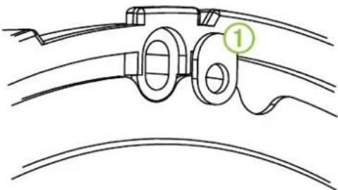
Side View
text_image
Technical diagram of a mechanical component with labeled parts ① and ②, showing cross-sectional views and dimension lines.| 1 | 130 mm (5.12 in.) |
| 2 | 220 mm (8.66 in.) |
A Sports model subwoofer is shown, but the dimensions are the same for the Classic model.
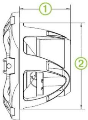
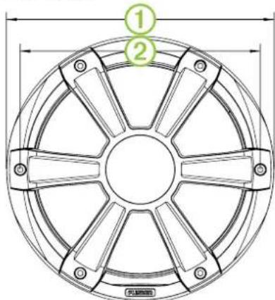
Sports Model Front View
text_image
① ②| 1 | 275 mm (10.83 in.) |
| 2 | 247 mm (9.72 in.) |
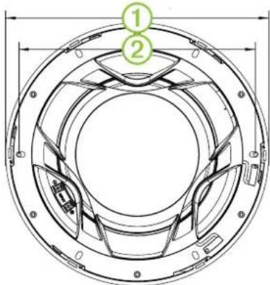
Classic Model Back View
text_image
Technical diagram of a circular mechanical component with numbered parts and dimension lines| 1 | 275 mm (10.83 in.) |
| 2 | 247 mm (9.72 in.) |
Cleaning the Subwoofer
NOTICE
Do not use harsh or solvent-based cleaners on the subwoofer. Using such cleaners may damage the product and void the warranty.
When mounted correctly, this subwoofer is rated IP65 for protection in the harsh marine environment from the front of the subwoofer. The subwoofer is not designed to withstand high pressure water spray, which may occur when you wash down your vessel. Failure to carefully spray-clean the vessel may damage the product and void the warranty.
1 Clean all salt water and salt residue from the grill with a damp cloth soaked in fresh water.
2 Use a mild detergent to remove a heavy buildup of salt or stains.
Troubleshooting
Before you contact your Fusion dealer or service center, you should perform a few simple troubleshooting steps to help diagnose the problem.
If the Fusion subwoofer has been installed by a professional installation company, you should contact the company so the technicians can assess the problem and advise you about possible solutions.
There is no sound coming from the subwoofer
- Verify that all connections are connected correctly to the proper terminals.
The system lacks bass
- Verify that the subwoofer is attached firmly to the mounting surface.
The audio is distorted
- Verify that the panels surrounding the subwoofer on the vessel are not rattling.
- Verify that the amplifier is connected to the subwoofer terminals correctly.
- If the subwoofer is connected to an amplifier, verify that the input level of the amplifier is matched to the output level of the stereo.
For more information, see the manual for the amplifier.
The LED lights will not turn on
- Verify that all wiring connections are correct and tight.
The LEDs pulse with the bass notes of the music
• Install a Fusion LED voltage regulator (SG-VREGLED).
Specifications
| Max. power (Watts) 450 W | |
| RMS power (Watts) 250 W | |
| Efficiency (1 W/1 m) 88 dB | |
| Frequency response (+ 3 dB) From 30 Hz to 2 kHz | |
| Min. mounting depth (clearance) 130 mm (5.125 in.) | |
| Mounting diameter (clearance) 223 mm (8.78 in.) | |
| Impedance 4 ohms | |
| Compass-safe distance* 520 cm (204.724 in.) | |
| LED supply voltage (Sports model only) | From 10.8 to 16 Vdc |
| LED load current at 14.4 Vdc (Sports model only) | 150 mA |
| Operating temperature range From 0 to 50°C (from 32 to 122°F) | |
| Storage temperature range From -20 to 70°C (from -4 to 158°F) | |
| Water and dust rating IEC 60529 IP65 | |
* This information is provided in accordance with the IEC Standard 60945. For more information, see below.
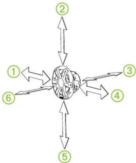
Subwoofer Compass-Safe Distance
All speakers and subwoofers contain magnets which are likely to cause interference with instruments on your boat. The size of the magnet used in the subwoofer affects how much interference the subwoofer may cause.
Interference can cause deviations and variations in the readings of sensitive navigational equipment, such as magnetic compasses. These deviations can cause inaccuracies or offsets in the readings, but will not harm the equipment. To alleviate the deviations, adjust the compass for the deviation following the manufacturer's instructions or move the subwoofer away from the navigational equipment. After moving a source of interference, you may need to recalibrate the compass.
To avoid deviations to navigational equipment, position the subwoofer so it is separated from the navigational equipment by at least the distance listed in the table below.
flowchart
graph TD
    A["①"] --> B["Central Component"]
    C["②"] --> B
    D["③"] --> B
    E["④"] --> B
    F["⑤"] --> B
    G["⑥"] --> B
| Direction from Subwoofer 10" Subwoofer | |
| 1 | 302 cm (9.9 ft.) |
| 2 | 295 cm (9.7 ft.) |
| 3 | 513 cm (16.8 ft.) |
| 4 | 277 cm (9.1 ft.) |
| 5 | 295 cm (9.7 ft.) |
| 6 | 488 cm (16.0 ft.) |
Amplifier Power Rating Recommendations
| 6.5" Speakers 30 to 90 W RMS, playing music |
| 7.7" Speakers 25 to 120 W RMS, playing music |
| 10" Subwoofer 50 to 300 W RMS, playing music |
Optimum Enclosure Recommendations
| Sealed enclosure volume* 17.2 L (0.6 ft. | ^3 |
| Ported (vented) enclosure volume** | 45 L (1.6 ft.) ^3 |
| Port diameter | 104 mm (4.0 in.) |
| Port length | 265 mm (10.45 in.) |
* Fully filled with absorption material.
** Lined with absorption material.
natural_image
Technical line drawing of a mechanical component with multiple screw holes and a central rotating shaft (no text or symbols)text_image
Technical diagram of a mechanical component with labeled parts ① and ②, showing internal structure and dimension lines.| 1 | 130 mm (5,12 po) |
| 2 | 220 mm (8,66 po) |
text_image
Technical diagram of a circular mechanical component with numbered parts and dimension lines| 1 | 275 mm (10,83 po) |
| 2 | 247 mm (9,72 po) |
natural_image
Technical line drawing of a mechanical component with multiple blades and a central circular housing (no text or symbols)natural_image
Pure technical line drawing of a mechanical component with no text or symbolstext_image
Technical diagram of a mechanical component with labeled parts and dimension lines| 1 | 130 mm (5,12 poll.) |
| 2 | 220 mm (8,66 poll.) |
text_image
Technical diagram of a circular mechanical component with numbered callouts indicating parts 1 and 2.| 1 | 275 mm (10,83 poll.) |
| 2 | 247 mm (9,72 poll.) |
Pulizia del subwoofer
AVVERTENZA
natural_image
Technical line drawing of a mechanical component with multiple screw holes and a circular housing (no text or symbols)text_image
Technical diagram of a mechanical component with labeled parts ① and ②, showing internal structure and dimension lines.| 1 | 130 mm (5,12 Zoll) |
| 2 | 220 mm (8,66 Zoll) |
text_image
Technical diagram of a circular mechanical component with numbered parts and dimension lines| 1 | 275 mm (10,83 Zoll) |
| 2 | 247 mm (9,72 Zoll) |
Reinigen des Subwoofers
HINWEIS
natural_image
Technical line drawing of a mechanical component with multiple screw holes and a central rotating shaft (no text or symbols)text_image
Technical diagram of a mechanical component with labeled parts ① and ②, showing internal structure and dimension lines.| 1 | 130 mm (5,12 in) |
| 2 | 220 mm (8,66 in) |
text_image
① ② PULBANONE| 1 | 275 mm (10,83 in) |
| 2 | 247 mm (9,72 in) |
text_image
Technical diagram of a circular mechanical component with numbered parts and dimension lines| 1 | 275 mm (10,83 in) |
| 2 | 247 mm (9,72 in) |
natural_image
Technical line drawing of a mechanical component with multiple screw holes and a central rotating shaft (no text or symbols)natural_image
Technical line drawing of a mechanical component with curved surfaces and a numbered label (1) in green, no readable text or symbols present.text_image
Technical diagram of a mechanical component with labeled parts ① and ②, showing internal structure and dimension lines.| 1 | 130 mm (5,12 pol.) |
| 2 | 220 mm (8,66 pol.) |
text_image
Technical diagram of a circular mechanical component with numbered parts and dimension lines| 1 | 275 mm (10,83 pol.) |
| 2 | 247 mm (9,72 pol.) |
natural_image
Technical line drawing of a mechanical component with multiple blades and a circular housing (no text or symbols)text_image
Technical diagram of a mechanical component with labeled parts and dimension lines| 1 | 130 mm (5,12 in.) |
| 2 | 220 mm (8,66 in.) |
text_image
Technical diagram of a circular mechanical component with numbered parts and dimension lines| 1 | 275 mm (10,83 in.) |
| 2 | 247 mm (9,72 in.) |