
F2AA001ABBK - Wall mount Furrion - Free user manual and instructions
Find the device manual for free F2AA001ABBK Furrion in PDF.
| Brand | Furrion |
| Model | F2AA001ABBK |
| Product Type | Universal Full Motion Outdoor Wall Mount |
| Maximum Load Capacity | 60 kg (132 lb) |
| VESA Compatibility | 100x100 mm to 400x400 mm |
| Tilt Angle | +3° (up) / -15° (down) |
| Swivel Angle | ±90° |
| Level Adjustment | ±5° |
| Wall Distance | 65 mm to 505 mm |
| Material | Steel with weather-resistant coating |
| Mounting | Solid concrete wall or wood studs (max 16 mm drywall) |
| Hardware Included | Screws, washers, anchors, spacers |
| Cable Management | Yes, built-in cable tie |
| Built-in Level | Yes |
| Maintenance and Cleaning | Clean with a dry cloth, inspect all screws periodically |
| Safety | Do not exceed maximum load, two-person installation, use safety tools |
| Warranty | See included warranty booklet |
| Contact | support@furrion.com |
Frequently Asked Questions - F2AA001ABBK Furrion
User questions about F2AA001ABBK Furrion
0 question about this device. Answer the ones you know or ask your own.
Ask a new question about this device
Download the instructions for your Wall mount in PDF format for free! Find your manual F2AA001ABBK - Furrion and take your electronic device back in hand. On this page are published all the documents necessary for the use of your device. F2AA001ABBK by Furrion.
USER MANUAL F2AA001ABBK Furrion
natural_image
Technical line drawing of a mechanical device with mounting brackets and internal components (no text or symbols)Important Safety Instruction....3
What's in the box 4
Before Installation....5
Configure the TV Bracket....6
Installation....7
Adjust the TV angle ....10
Cable Management....10
Français....11
Bienvenue....11
Thank you for purchasing the Furrion Universal Outdoor Full Motion Mount for 43"/49"/55"/65" Furrion Aurora™ TV. Before operating your new product, please read these instructions carefully. This instruction manual contains information for safe use, installation, introduction of the product. Please keep this manual for future reference.
The manufacturer does not accept responsibility for any damages from incorrect installation due to not observing these instructions.
If you have any further questions regarding our products, please contact us at
support@furrion.com
Important Safety Instruction
WARNING
This product is designed to be installed on wood stud or solid concrete walls. Before installing make sure the wall or mounting surface will safely support four times the combined weight of the mounted equipment, including its accessories. Never exceed the Maximum Load Capacity (132 lbs/60 kg).
PLEASE NOTE: Improper installation will void warranty and may cause serious injury or damage. It is recommended that a qualified contractor installs the full motion mount.
Safety Precaution
- Ensure these instructions are thoroughly understood before attempting installation. If unsure of any part of the installation process, contact a professional installer for assistance.
- Be careful not to pinch fingers during installation.
- At least two people are required for this installation and it is highly recommended that this product is installed by qualified professionals.
- Screws must be tightly secured, but do not overtighten screws. Over tightening can damage the items, greatly reducing their holding power.
- Always use an assistant or mechanical lifting equipment to safely lift and position equipment.
- Safety gear and proper tools must be used. Failure to do so can result in property damage and/or serious injury.
- This wall mount is intended for use only with the maximum weight of 132 lbs (60 kg). Use with products heavier than the maximum weight indicated may result in instability causing possible injury.
- Care and clean: Clean your mount regularly with a dry cloth. Inspect all screws and hardware periodically, including tilt/level adjustment screws, to ensure that no connections become loose over time. Re-tighten as needed.
What's in the box
Unpack the box carefully and check if the following parts are included. If any parts are missed or damaged, do not attempt to assemble the product. Please contact the authorized retailer where you purchased immediately.
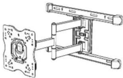
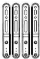
natural_image
Technical line drawing of a mechanical assembly with mounting bracket and housing (no text or symbols)Mount Assembly x 1 Adapter Bars x 4
Instruction Manual & Warranty Manual
Wall Plate Paper Template
Hardware Kit (A\~M)
WARNING: This product contains small items that could be a choking hazard if swallowed.
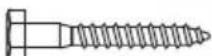
(A)lag bolt
ST8*63 (x 6)
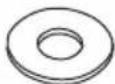
(B)washer 9.5^ 21^2.0(x6)
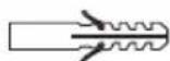
(C) anchor
Φ10*50/PA6 (x 6)

(D)Phillips bolt M6*16 (x 4)

(E) Phillips bolt M6*18 (x 4)
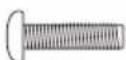
(F) Phillips bolt M6*25 (× 4)
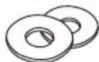
(G) washer
Φ6.4*Φ18*1.5 (x 4)

(H) Phillips bolt M8*10 (x 8)

(I) Phillips bolt M8*18 (x 4)
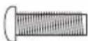
(J) Phillips bolt M8*25 (x 4)
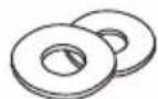
(K) washer
Φ8.4*Φ19*2.0 (x 4)

(L) spacer (ABS)
Φ8*Φ18*10 (× 8)
natural_image
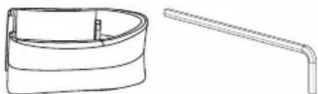
Technical line drawing of a cylindrical tank and a bent pipe (no text or symbols)(M) Cable Management Clip (x 1) Allen Key (x 1)
Before Installation
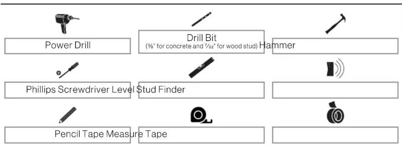
Tools Needed (not included)
flowchart
graph TD
    A["Power Drill"] --> B["Phillips Screwdriver Level"]
    B --> C["Pencil Tape Measure Tape"]
    D["Drill Bit (¾" for concrete and 7½2" for wood stud)"] --> E["Stud Finder"]
    F["Hammer"] --> G["Measurement Icon"]
    H["Water Tap"] --> I["Water Tap Icon"]
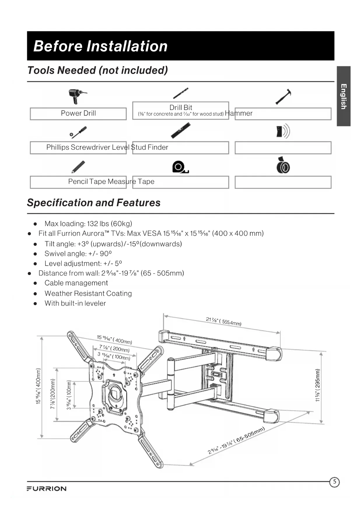
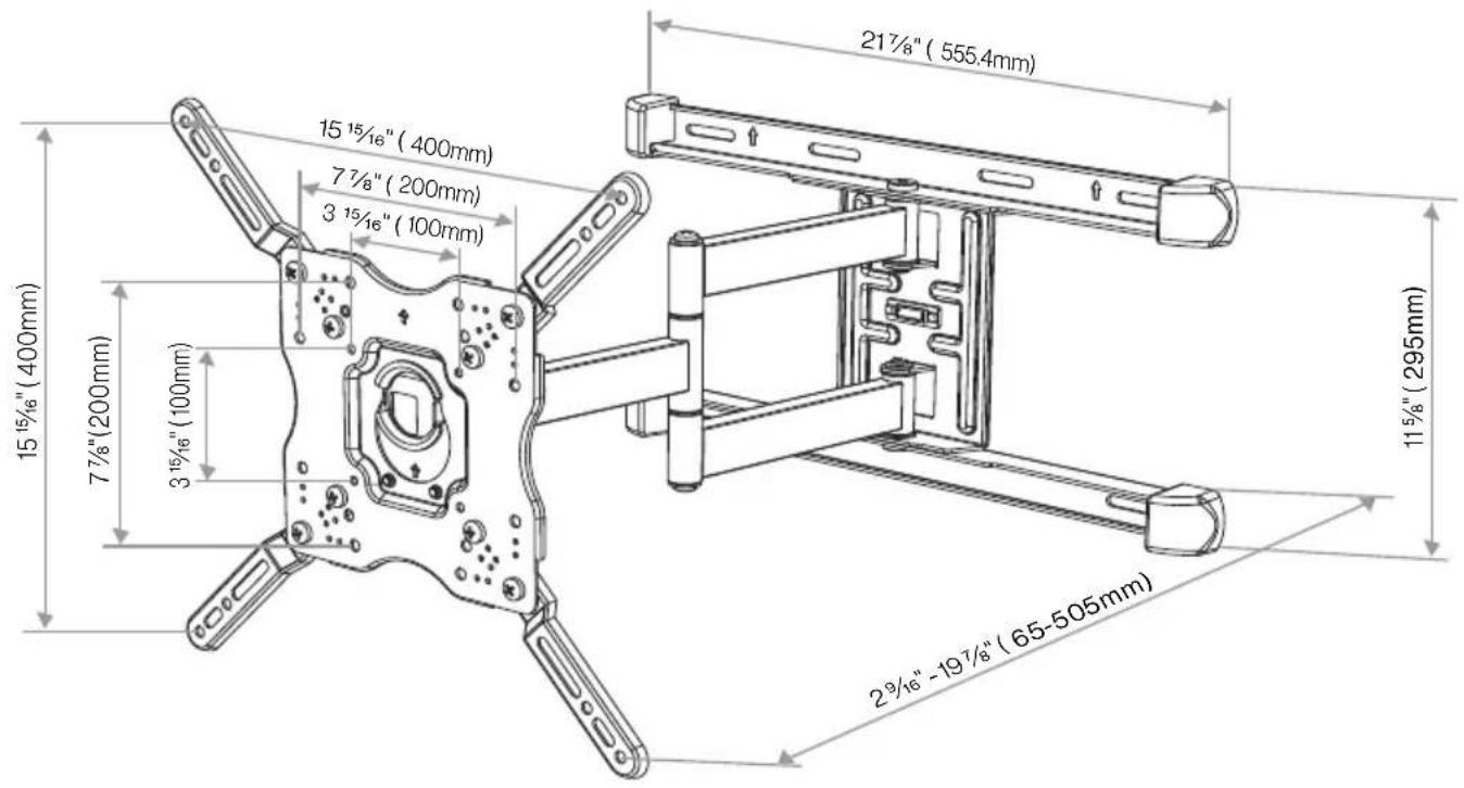
Specification and Features
• Max loading: 132 lbs (60kg)
- Fit all Furrion Aurora™ TVs: Max VESA 15 ^15/16 " x 15 ^15/16 " (400 x 400 mm)
- Tilt angle: +3^ (upwards)/ -15^ (downwards)
- Swivel angle: + / - 90^
• Level adjustment: +/- 5°
• Distance from wall: 2^9/16 "-19 ^7/8 " (65 - 505mm)
- Cable management
• Weather Resistant Coating
- With built-in leveler
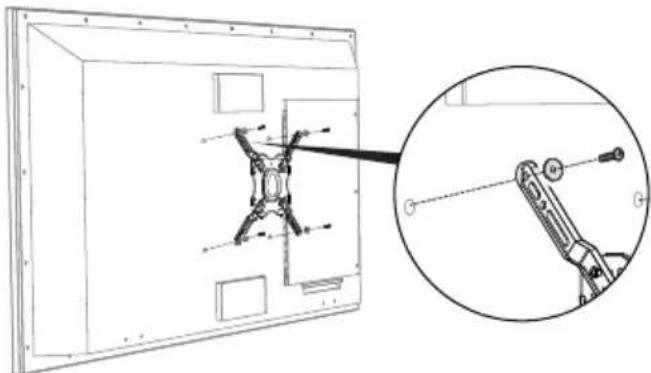
Configure the TV Bracket
- Remove the TV bracket from the mount assembly firstly.
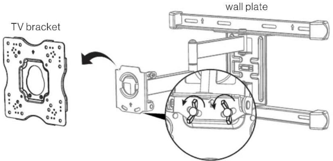
-
Choose one kind of configuration from below A, B, C, D based on your TV and assemble the TV bracket.
-
TV bracket expands to fit TV hole patterns from 3^15/16" × 3^15/16" (100 x 100 mm) to 15^15/16" × 15^15/16" (400 x 400 mm).
• Measure the width and height of your TV hole pattern with a tape measure. - Assemble the TV bracket with 4 adaptor bars and 8 M8*10 screws (H) for below B, C or D configuration and keep the screws untightened, slight adjust the 4 adaptor bars to make the mounting holes aligned with the ones on the TV back, tighten the screws to fix the 4 adaptor bars.
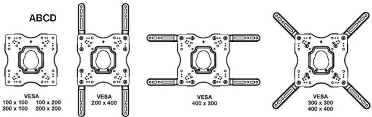
Furrion Aurora ™ TV VESA MOUNTING PATTERN
| TV Models Width (mm) Height (mm) Screw | |||
| FDUP43CBRFDUF43CBR | 200 200 | M6*15mm(x4) | |
| FDUP49CBRFDUF49CBR | 200 400 | ||
| FDUP55CBRFDUF55CBRFDUP65CBRFDUF65CBR | 400 400 | ||
Installation
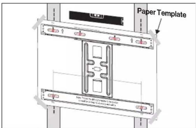
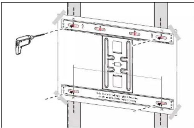
Step 1 - Mounting the Wall Plate on Wall
Warning: Do not drill into mortar joints. Be sure to drill holes centered within studs or bricks.
A. Mounting on solid concrete or concrete block wall
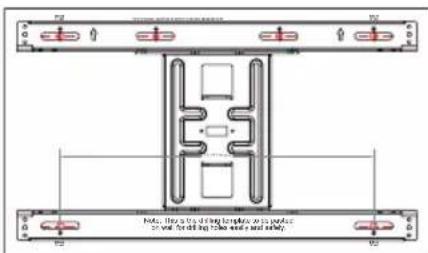
- Choose a proper height for your TV. Level the wall plate paper template on wall and paste it in place for your safe drilling.
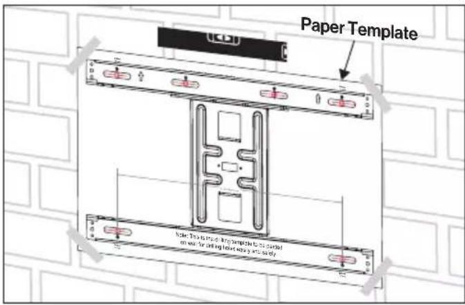
- Using a 3/8" (10 mm) drill bit, drill 6 pilot holes into solid concrete.
Note: Pilot holes must be drilled to a depth of 3" (75 mm).
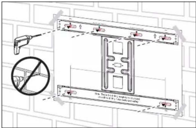
- Remove the wall plate paper template from wall and insert 6 concrete anchors (C) into the holes. You can use a hammer to lightly tap the anchors into place if necessary.
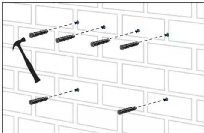
Caution: Ensure that the anchor is flush with the concrete surface.
- Install the wall plate on wall using 6 lag bolts (A) and washers (B). Tighten the lag bolts securely so that wall plate is firmly attached to wall.
natural_image
Technical line drawing of a mechanical assembly mounted on a brick wall, showing components like gears and rods (no text or symbols)Warning: Do not over tighten. Over tightening can damage the lag bolts, greatly reducing their holding power.
Installation
B. Mounting on a wood stud wall covered with gypsum board (drywall)
- Use a stud finder to firstly find both the edges of the wooden stud. Locate the center of each wooden stud and mark the center lines for two studs.
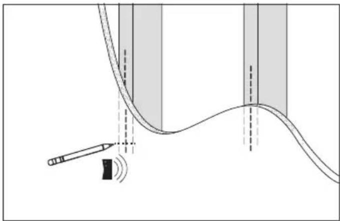
natural_image
Diagram showing a curved line with a pencil and a sensor emitting sound waves, surrounded by shaded vertical bands (no text or symbols)Note: Drywall covering the wood stud wall must not exceed 16 mm ( ^5/_8 ).
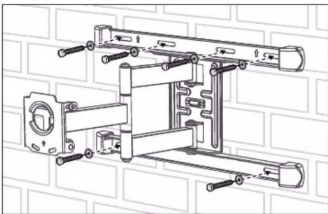
- Place the wall plate paper template against the wall to ensure the 4 holes line up with the stud center lines. Level the wall plate paper template and paste it in place.
Note: The mounting hole must be centered on the stud.
- Using a 732 " (5.5mm) drill bit, drill 4 pilot holes. Then remove the wall mount paper template from wall.
Note: Pilot holes must be drilled to a depth of 3" (75 mm).
- Install the wall plate on wall using 4 lag bolts(A) and washers (B). Tighten the lag bolts securely so that wall plate is firmly attached to wall.

natural_image
Technical line drawing of a mechanical assembly with mounting brackets and bolts (no text or symbols)Warning: Do not over tighten.
Installation
Step 2 - Attach TV Bracket to TV Display
- Determine the correct length and diameter of screws based on your TV hole patterns.
- If your TV back is flat, use the shorter screws with washers.
- If your TV back is irregular or curved, use the longer screws with washers and spacers (L).
* For Furrion Aurora™ TV, please use the screw size M6 *15 (D) and washers (G) to attach the TV bracket to TV back.
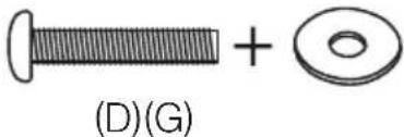
- Assemble the configured TV bracket on the back of Furrion Aurora™ TV by using 4 x M6*15 screws (D) and washers (G). Ensure the bracket is vertically centered and level. Tighten the screws (D) to ensure the TV bracket securely attached on TV back.
natural_image
Technical line drawing of a mechanical assembly with an inset close-up showing a bracket and pin (no text or symbols)Warning: Make sure to use the correct length screw for your TV. A screw that is too long might damage your TV.
Step 3 - Hang TV on the Wall Plate
Caution: Please use at least two people to move and install the TV on the wall plate.
- Hang the TV onto the arm of wall plate by hooking the top support firstly, then resting the TV into place.
NOTE: A fixing strap is suggested to apply to prevent the moving of the arm while attaching an TV in windy environment.
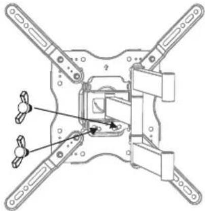
natural_image
Technical line drawing of a mechanical assembly with cross-shaped components and a separate view showing a bracket assembly (no text or symbols)- Rotate the two knobs on the bottom of arm mount clockwise to fix the TV onto wall plate securely.
natural_image
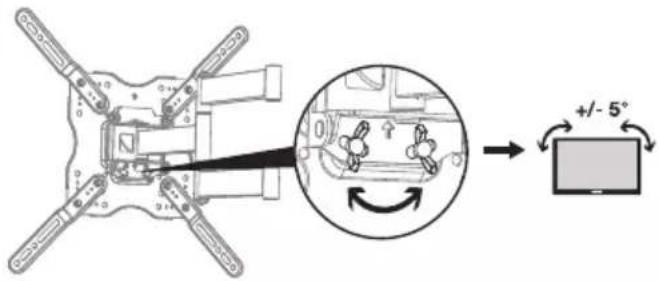
Technical line drawing of a mechanical assembly with four arms and a central component (no text or symbols)Adjust the TV angle
LEVEL ADJUSTMENT
You could turn the rotating knobs by hand to adjust the leveling of your TV. Once adjustment is finished, tighten the knobs firmly in place.
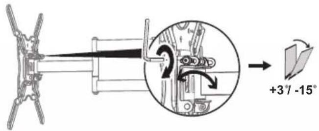
TILT ADJUSTMENT
You could slightly loosen both tilt tension screws with the Allen Key (M) to adjust the tilt angle for optimal viewing position. Once adjustment is finished, tighten both screws firmly in place with the Allen Key (M).
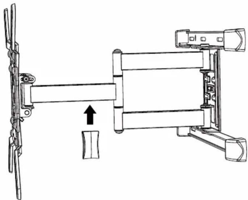
Cable Management
The Cable Management Clip is supplied to be added on the mounting arm for keeping your cables organized and protected.
natural_image
Technical line drawing of a mechanical assembly with no visible text or symbolsBienvenue
natural_image
Technical line drawing of a mechanical assembly with mounting bracket and housing (no text or symbols)
natural_image
Technical line drawing of a cylindrical container and a bent pipe (no text or symbols)(M) attache passe-câbles (x 1) clé hexagonale (x 1)
natural_image
Technical line drawing of a mechanical assembly mounted on a brick wall, showing components like gears and rods (no text or symbols)natural_image
Diagram showing a curved line with a pencil and a sensor emitting sound waves, no text or symbols presentnatural_image
Technical line drawing of a mechanical assembly with mounting brackets and bolts (no text or symbols)natural_image
Technical line drawing of a mechanical assembly with an inset close-up showing a bracket and shaft (no text or symbols)natural_image
Technical line drawing of a mechanical assembly with mounting holes and a bracket (no text or symbols)natural_image
Technical line drawing of a mechanical assembly with four arms and a central component (no text or symbols)natural_image
Technical line drawing of a mechanical device with directional arrow indicating motion (no text or symbols)Bienvenido
natural_image
Technical line drawing of a mechanical assembly with two components, no visible text or symbols
natural_image
Technical line drawing of a mechanical assembly mounted on a brick wall, showing components like gears and rods (no text or symbols)natural_image
Diagram showing a curved line with a pencil and a sensor emitting sound waves, overlaid on shaded vertical bands (no text or symbols)natural_image
Technical line drawing of a mechanical assembly with mounting brackets and bolts (no text or symbols)natural_image
Technical line drawing of a mechanical assembly with an inset close-up showing a bracket and shaft (no text or symbols)natural_image
Technical line drawing of a mechanical assembly with mounting holes and a bracket (no text or symbols)natural_image
Technical diagram of a mechanical device with four blades and a central component (no text or symbols)natural_image
Technical line drawing of a mechanical assembly with no visible text or symbolsFURRION
Furrion Innovation Center & Institute of Technology
• 52567 Independence Ct., Elkhart, IN 46514, USA • Toll free:1-888-354-5792
- Email: support@furrion.com
©2007-2019 Furrion Ltd. Furrion® and the Furrion logo are trademarks licensed for use by Furrion Ltd. and registered in the U.S. and other countries.
- Français....11
- Important Safety Instruction
- WARNING
- Safety Precaution
- What's in the box
- Hardware Kit (A\~M)
- Before Installation
- Specification and Features
- Configure the TV Bracket
- Installation
- Step 1 - Mounting the Wall Plate on Wall
- Mounting on solid concrete or concrete block wall
- Mounting on a wood stud wall covered with gypsum board (drywall)
- Step 2 - Attach TV Bracket to TV Display
- Step 3 - Hang TV on the Wall Plate
- Adjust the TV angle
- LEVEL ADJUSTMENT
- TILT ADJUSTMENT
- Cable Management
- Bienvenue
- Bienvenido
- FURRION
- Furrion Innovation Center & Institute of Technology
Brand : Furrion
Model : F2AA001ABBK
Category : Wall mount