DHW 400+ - Heat pump DIMPLEX - Free user manual and instructions
Find the device manual for free DHW 400+ DIMPLEX in PDF.


| Product type | Thermodynamic water heater (heat pump) |
| Brand | Dimplex |
| Model | DHW 400+ |
| Dimensions (H x W x D) | 2043 x 740 x 776 mm |
| Weight (empty) | 132 kg |
| Tank volume | 385 liters |
| Power supply | 230 V, 50 Hz, single-phase |
| Maximum total power consumption | 2200 W |
| Electric resistance power | 1500 W |
| COP (EN 16147 cycle XL45) | 3.3 |
| Refrigerant | R134a (0.95 kg) |
| Set temperature range | 25 °C to 85 °C |
| Air operating range | 7 °C to 35 °C |
| Nominal tank pressure | 6 bars |
| Sound power level | 60 dB(A) |
| Maximum air duct length | 10 m (DN 160) |
| Anti-corrosion anode | Magnesium, check every 2 years |
| Safety | HP pressure switch, temperature limiter (95 °C) |
| Special functions | Thermal disinfection, solar, photovoltaic, bivalent |
| Maintenance | Evaporator cleaning, anode check, condensate inspection |
| Repairability | Anode, filters, accessible components |
Frequently Asked Questions - DHW 400+ DIMPLEX
User questions about DHW 400+ DIMPLEX
0 question about this device. Answer the ones you know or ask your own.
Ask a new question about this device
Download the instructions for your Heat pump in PDF format for free! Find your manual DHW 400+ - DIMPLEX and take your electronic device back in hand. On this page are published all the documents necessary for the use of your device. DHW 400+ by DIMPLEX.
USER MANUAL DHW 400+ DIMPLEX
natural_image
Line drawing of a cylindrical industrial water heater with control panel and side door (no text or symbols)Installation and Operating Instruction
Hot Water Heat Pump for Indoor Installation
R1 Fühler Lufteintritt
R3 Fühler Warmwasser
R5 Fühler Warmwasser regenerativ (optional)
R13 Fühler Regenerativ (optional)
natural_image
Technical diagram showing a rectangular component with internal components and a red X-shaped line indicating a crossed-out section (no text or symbols present)natural_image
Technical line drawing of a mechanical device with labeled components (no readable text or symbols)natural_image
Technical line drawing of a mechanical assembly with no visible text or symbolsAbb. 8.1: Anode Elektoheizung
natural_image
Empty white rectangle with black border (no text or symbols)Table of contents
1 Please read immediately....EN-2
1.1 Important notes....EN-2
1.2 Intended use......EN-2
1.3 Regulations / safety information......EN-2
2 Description......EN-3
2.1 General......EN-3
2.2 Refrigerant circuit (heat pump operating principle)......EN-3
2.3 Safety and control devices....EN-4
2.4 Temperature sensor....EN-4
3 Storage and transport......EN-5
3.1 General......EN-5
3.2 Fork lift (or lift truck) transport......EN-5
3.3 Manual transport (factory default)......EN-5
3.4 Transport in carrier (accessory with locking plate)......EN-5
3.5 Opening the device....EN-6
4 Installation....EN-6
4.1 Installation location....EN-6
4.2 Installation....EN-6
5 Assembly....EN-7
5.1 Connecting the water pipes....EN-7
5.2 Connecting the condensate pipe....EN-7
5.3 Electrical connection....EN-7
5.4 Air duct connection (optional)......EN-7
6 Commissioning......EN-8
6.1 Domestic hot water system......EN-8
7 Operation and function of the domestic hot water heat pump......EN-8
7.1 Operation and display ....EN-8
7.2 Menu structure ......EN-9
7.3 Functions......EN-12
8 Maintenance / repair......EN-13
8.1 Water circuit / condensate drain......EN-13
8.2 Air circuit supply......EN-13
8.3 Corrosion protection anode EN-14
9 Faults / troubleshooting (for the user)...... EN-14
10 Decommissioning ...... EN-14
11 Environmental requirements...... EN-14
12 Device information ...... EN-15
Anhang · Appendix · Annexes ...... A-I
Maßbild / Dimension drawing / Schéma coté ...... A-II
1 Please read immediately
1.1 Important notes
CAUTION!
Read these installation and operating instructions before commissioning!
CAUTION!
Work on the domestic hot water heat pump is to be performed by qualified personnel only! Observe accident prevention regulations!
CAUTION!
The device cover cannot be used for carrying (the cover cannot withstand significant forces).
CAUTION!
Once the heat pump has been set up, the guard plate must be removed!
CAUTION!
The heat pump must not be transported overhead.
CAUTION!
When installing the on-site pipework, ensure that the pipes are not contaminated (flush pipes before connecting the domestic hot water heat pump if necessary).
CAUTION!
The domestic hot water heat pump must only be operated when filled with water.
CAUTION!
The collector sensor must be a temperature sensor with the resistance characteristic curve of a PT1000 (see Cap. 2.4.2 on pag. 4).
CAUTION!
Disconnect the power supply before opening the domestic hot water heat pump; possible fan coasting must be considered.
CAUTION!
Risk of injury caused by sharp-edged fins. Fins must not be deformed or damaged!
CAUTION!
The device must be de-energised before it can be opened.
CAUTION!
The terminal X8 can also be energized when the heat pump is in switched-off state
CAUTION!
For settings for using photovoltaic energy, a solar thermal system or an external boiler, domestic hot water temperatures of >60 ^ are possible and an external scald protection must therefore be in place.
1.2 Intended use
This device is only intended for use as specified by the manufacturer. Any other use beyond that intended by the manufacturer is prohibited. This requires the user to abide by the relevant project planning documents. Please refrain from tampering with or altering the device.
1.3 Regulations / safety information
CAUTION!
Read these installation and operating instructions before commissioning!
The domestic hot water heat pump is used exclusively to heat water for domestic use and drinking water within the specified operating temperature limits. The heating of fluids other than domestic water is not permitted. Technical regulations for domestic water installation are to be observed. The nominal pipe widths for the on-site sanitary installation must be determined taking into account the building-specific requirements and the valid directives and regulations. Any necessary safety devices, such as pressure reducing valves, must be installed according to the specific requirements.
■ The following are not permitted:
- Operating the pump with solvent-based or explosive exhaust air
- The use of exhaust air containing grease, dust or aerosols
containing adhesive substances
- The connection of extractor hoods to the ventilation system
It is not permissible to install the device:
- Outdoors
- In rooms which are exposed to frost
- In rooms subject to high humidity (e.g. bathrooms)
- In rooms with air which is potentially explosive due to gases, vapours or dust
It is not permissible to operate the device:
- With an empty cylinder
- During the construction phase of the building
The construction and design of the domestic hot water heat pump complies with the relevant EU directives. (See also CE declaration of conformity).
The technician must ensure that the refrigerant is flushed adequately to allow maintenance and repair work to be carried out on refrigerant circuit components without risk. Refrigerant must be properly handled and disposed of; it must not be released into the environment!
The refrigeration circuit is "hermetically sealed" and contains the fluorinated refrigerant R134a included in the Kyoto protocol. Information on the GWP value and CO_2 equivalent of the refrigerant can be found in the chapter Device information. The refrigerant is CFC-free, non-ozone depleting and non-combustible.
■ Always disconnect the power supply before carrying out any work on the domestic hot water heat pump.
When connecting the domestic hot water heat pump to the power supply, the relevant VDE, EN and IEC standards must be complied with. Also observe the technical connection requirements of the electrical utility companies.
This heat pump is designed for use in a domestic environment according to Article 1, Paragraph 2 k) of EU directive 2006/42/EC (machinery directive) and is thus subject to the requirements of EU directive 2014/35/EU (low-voltage directive). It is thus also intended for use by non-professionals for heating shops, offices and other similar working environments, agricultural establishments and hotels, guesthouses and other residential buildings.
CAUTION!
Work on the domestic hot water heat pump is to be performed by qualified personnel only!
Observe accident prevention regulations!
2 Descripti
2.1 General
The domestic hot water heat pump is a ready-to-use heating device whose main components are a domestic hot water cylinder, the components of the refrigerant, air and water circuits and the control, regulation and monitoring devices required for automatic operation.
With the help of electrical energy, the domestic hot water heat pump uses the heat stored in the drawn-in air for domestic hot water preparation. The optional internal heat exchanger can be connected to additional heat generators such as boilers and solar energy systems. The units are equipped with an electric heater (1.5 kW) as standard.
The temperature of the drawn-in air (the heat source) serves as the reference value for the energy consumption, the domestic hot water preparation heat-up time and domestic hot water temperature.
For this reason, an air duct system (DN 160, max. length 10 m) can be connected to the standard spigot of the domestic hot water heat pump for targeted waste heat recovery. For the heat pump to be operated effectively, air short-circuits between the drawn-in air and the blown-out air must always be avoided. This can, for example, be achieved through the use of a bend on the intake and outlet side.
Falling outlet air temperatures reduce the heat pump's heat output and increase the heat-up time. In order for the heat pump to be operated economically, the air intake temperature should not fall below 15 °C for an extended period.
The electric heater fulfils the following functions:
■ Supplementary heating
With the "Boost" key, the domestic hot water preparation can be supported with the electric heater for an adjustable period of time.
Operating limit
If the air intake temperature falls below 7 ± 1.0 °C, the electric heater switches on automatically and (nominally) heats the water up to the domestic hot water set temperature.
Emergency heating
In the event of a heat pump fault, the domestic hot water supply is maintained by the electric heater.
■ Preventative thermal disinfection
Using the operator panel keypad, domestic hot water temperatures above 60 °C (up to 85 °C) can be programmed via the "thermal disinfection" menu item.
■ Reheating
Water temperatures over 60 °C are achieved with the electric heater.
NOTE
When the domestic hot water temperature reaches > 60 °C, the heat pump switches off and the domestic hot water preparation takes place solely by the electric heater. The factory setting for the heating element controller is 65 °C.
2.2 Refrigerant circuit (heat pump operating principle)
The refrigerant circuit is a closed system in which the R134a refrigerant is the work material. The finned heat exchanger extracts heat from the drawn-in air at a low evaporation temperature, and transfers it to the refrigerant. The vaporous refrigerant is taken in by a compressor, where it is compressed to a higher pressure and temperature level before being transported to the liquefier, where the heat absorbed in the evaporator and part of the compressing energy is transferred to the water. Subsequently, the high condensation pressure is lowered to the evaporation pressure by a throttle mechanism (expansion valve), and the refrigerant can again extract heat from the intake air in the evaporator.
2.3 Safety and control devices
The domestic hot water heat pump is equipped with the following safety devices:
High pressure switch (HP)
The high pressure switch protects the heat pump against unacceptably high operating pressure in the refrigerant circuit and switches the heat pump off in the event of a fault. The heat pump restarts with a time delay when the pressure in the refrigerant circuit has dropped again.
Safety temperature limiter for electric heater (STL)
The STL prevents impermissibly high temperatures from developing in the domestic hot water cylinder.
The electric heater switches off if the set switching value (95 °C) is exceeded.
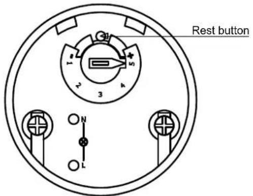
The electric heater cannot be switched on again until the domestic hot water temperature has decreased to ≤90 ^ and the reset button (see illustration) on the STL (under flange cover) is pressed (this must only be done by qualified personnel).
The domestic hot water heat pump is also equipped with the following regulation and control devices:
Heat pump temperature controller
Temperature control in the domestic hot water cylinder and the regulation for compressor operation is carried out by the control electronics. Electronic sensors measure the water temperature, which is regulated based on the setpoint. The desired temperature level (setpoint) is set via the keypad on the control panel.
Air intake temperature
The sensor connected to the controller measures the temperature in the domestic hot water heat pump directly in front of the evaporator (air intake temperature). If the set switching value is not reached (7 ±1 °C, reset value 2 K,
delay 30 min), the domestic hot water preparation is switched automatically from heat pump operation to heating element operation.
2.4 Temperature sensor
2.4.1 Temperature sensor installation position
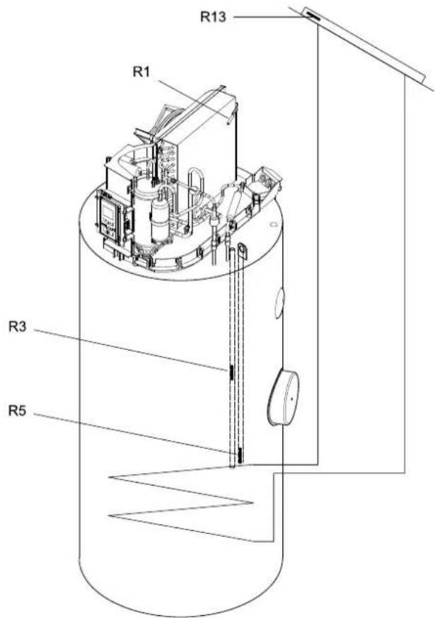
R1 Air inlet sensor
R3 Domestic hot water sensor
R5 Domestic hot water renewable sensor (optional)
R13 Renewable sensor (optional)
2.4.2 Measured values temperature sensor
Measured values NTC 10 sensor (R1, R3, R5)
| Temperature in °C | -20 | -15 | -10 | -5 | 0 | 5 | 10 | ||
| NTC-10 in kΩ | 67.7 | 53.4 | 42.3 | 33.9 | 27.3 | 22.1 | 18.0 | ||
| 15 | 20 | 25 | 30 | 35 | 40 | 45 | 50 | 55 | 60 |
| 14.9 | 12.1 | 10.0 | 8.4 | 7.0 | 5.9 | 5.0 | 4.2 | 3.6 | 3.1 |
Measured values PT 1000 sensor (R13)
| Temperature in °C | -30 | -20 | -10 | 0 | 10 | 20 | 30 | 40 | 50 | ||
| PT 1000 in kΩ | 0.882 | 0.022 | 0.961 | 1.00 | 1.039 | 1.078 | 1.117 | 1.155 | 1.194 | ||
| 60 | 70 | 80 | 90 | 100 | 110 | 120 | 130 | 140 | 150 | 160 | |
| 1.232 | 1.271 | 1.309 | 1.347 | 1.385 | 1.423 | 1.461 | 1.498 | 1.536 | 1.573 | 1.611 | |
3 Storage and transport
3.1 General
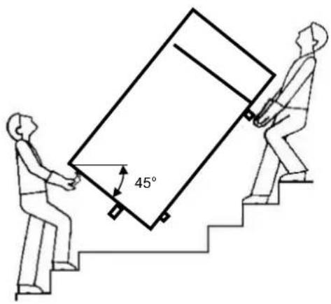
The domestic hot water heat pump should always be stored and transported packaged in an upright position, without being filled with water. If handled carefully, the device can be transported over short distances with a maximum tilt angle of 45^ . Ambient temperatures between -20 and +60 ^ C are permissible during transport and storage.
3.2 Fork lift (or lift truck) transport
The domestic hot water heat pump must remain mounted on the pallet when being transported with a fork lift. The pump should be lifted slowly. Because of its high centre of mass, the domestic hot water heat pump must be secured against toppling. To prevent damage, the domestic hot water heat pump must be lowered onto a level surface.
3.3 Manual transport (factory default)
The wooden pallet can be used underneath the device for the purpose of manual transportation. A second or third carrying position can be created with the help of ropes or carrying slings (these may be wrapped around the cylinder casing and attached to the water pipe nipples). When transporting the heat pump in this manner (or with a hand truck), do not, under any circumstances, exceed the max. tilt angle of 45^ (see illustration).
CAUTION!
The device cover cannot be used for carrying (the cover cannot withstand significant forces).
3.4 Transport in carrier (accessory with locking plate)
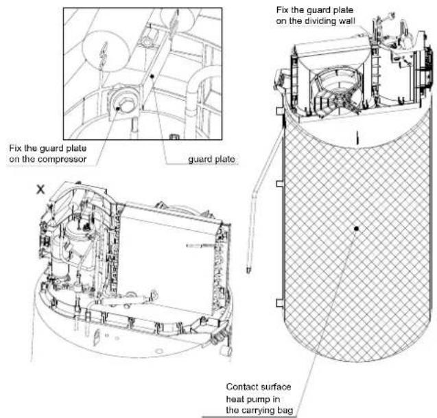
The carrying bag accessory can be used to transport the heat pump horizontally within the building. For this, the cover must be removed and the guard plate supplied with the carrying bag must be mounted. The guard plate is fixed in place between the transport lug of the compressor and the dividing wall using the mounting material provided.
CAUTION!
Once the heat pump has been set up, the guard plate must be removed!
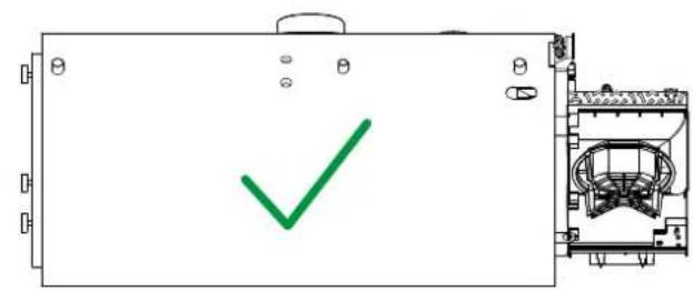
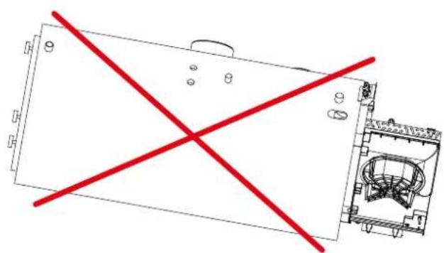
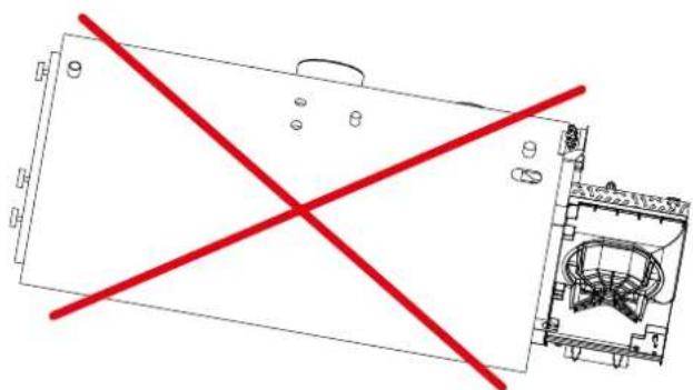
It is important to ensure that the device is not transported overhead during the entire transport process.
natural_image
Technical line drawing of a device with red X-shaped lines indicating crossed-out sections (no text or symbols present)CAUTION!
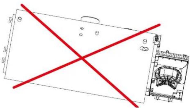
The heat pump must not be transported overhead.
3.5 Opening the device
The device cover is divided in two. To access the inside of the device or to make transport easier (prevent damage), both cover parts can be removed. To do this, the four locks must be opened with quarter-turns in anti-clockwise direction (the lock symbol pointing towards the front shows the status of the lock). The cover can then be removed to the front.
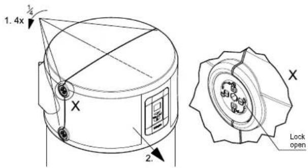
To remove the air circuit cover, the two locking screws must be removed. The cover can then be removed to the rear.

4 Installation
4.1 Installation location
Installation location criteria:
■ The domestic hot water heat pump must be installed in a dry and frost-free room.
Furthermore, installation and air intake is not permitted in rooms with air which is potentially explosive because of gases, vapours or dust.
In order to prevent damage to interior walls caused by humidity, good thermal insulation between the room into which the exhaust air is released and the neighbouring rooms is recommended.
■ Condensate drainage (with a siphon) must be provided.
The air taken in may not be excessively contaminated or contain large amounts of dust.
The load-bearing capacity of the foundation must be sufficient (the weight of the filled domestic hot water heat pump is approx. 550 kg).
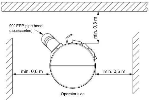
For fault-free operation and for any maintenance and repair work, minimum clearances of 0.6 m are required on the left and right of the device (see illustration). The domestic hot water heat pump can be connected (optionally) using EPP air ducts NW 160 mm internal, 190 mm external, which must not exceed a total length of 10 m.
If air ducts are not used, a 90° EPP pipe bend pointing downwards on the outlet side can be used for sound optimised operation (see illustration)
4.2 Installation
■ Remove the three transport restraint screws (M12 - fixing the device to the pallet) from the bottom of the pallet.
■ Remove the pallet and mount the three M12 supporting feet (in the plastic bag attached to the nipple of the cylinder pipe).
■ Position the domestic hot water heat pump and align it vertically by adjusting the device feet. Then tighten the counter nuts on the device feet.
5 Assembly
5.1 Connecting the water pipes
The water connections (see scaled diagram (Cap. 1 on pag. II)) are located at the rear of the unit.
NOTE
Circulation pipe
For energy efficiency reasons, a circulation pipe should not be used if this can be avoided. If a circulation pipe is installed in the domestic hot water distribution system, a valve or a similar device must be provided as shut-off facility to avoid unnecessary energy losses. Circulation is enabled according to use (time or requirement control).
The nominal pipe widths for the on-site sanitary installation must be determined by taking into account the available water pressure and any pressure drops expected to occur in the pipework.
Technical regulations for domestic water installation are to be observed. The nominal pipe widths for the on-site sanitary installation must be determined taking into account the building-specific requirements and the valid directives and regulations. Any necessary safety devices, such as pressure reducing valves, must be installed according to the specific requirements.
Both rigid and flexible water pipes may be used. Observe the corrosion behaviour of the pipework materials used in order to avoid corrosion damage (see section Commissioning).
NOTE
Domestic hot water, cold water and circulation connections: These pipe nipples contain plastic inserts, the purpose of which is to protect against corrosion (in particular to the pipe nipple flange surfaces). These plastic inserts remain in their positions after installation.
CAUTION!
When installing the on-site pipework, ensure that the pipes are not contaminated (flush pipes before connecting the domestic hot water heat pump if necessary).
5.2 Connecting the condensate pipe
The condensate hose is routed through the cladding at the rear of the device. It should be routed in such a way that the condensate produced (during heat pump operation) can flow away freely.
There is a pressureless seal valve at the end of the condensate hose, which must be relocated accordingly if the condensate hose is shortened (the valve can be easily removed and re-inserted). The condensate should be drained into a siphon (also refer to the maintenance information in section 8.1).
NOTE
The sealing lip valve must be used to prevent damage from condensate.
5.3 Electrical connection
The domestic hot water heat pump is wired ready for use; power is supplied via the power supply, which is plugged into an earthed wall socket (\~230 V, 50 Hz). This socket must remain accessible after installation. In order to control external devices, e.g. the 2nd heat generator, solar circulating pump or collector temperature sensor, a separate cable must be connected to the device via an available cable gland and strain relieved. Do this by opening the device cover as described in Cap. 3.5 on pag. 6. The relevant connection points of the components can be found in the electrical circuit diagram Cap. 3 on pag. VI and the electrical documentation.
5.4 Air duct connection (optional)
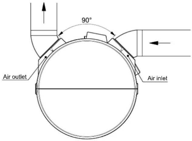
The device is designed for connecting an EPP air duct (individual components available as accessories DN 160 inside). The 90° position of the two connecting stubs means that a wide range of ducts are possible.
6 Commissioning
6.1 Domestic hot water system
CAUTION!
The domestic hot water heat pump must only be operated when filled with water.
Domestic hot water system requirements
The following materials can be used in the consumer's domestic hot water system:
Copper
Stainless steel
Brass
Plastic
Depending on the materials used in the domestic hot water system (customer installation), material incompatibility may lead to corrosion damage. This especially applies to zinc-plated materials and materials containing aluminium. If there is a risk of water contamination during operation, it may be necessary to install a filter.
Commissioning the domestic hot water system
All installations for the water circuit and air circuit, as well as all electrical installations, must have been carried out correctly and fully completed.
- Fill the domestic hot water circuit via an external connection.
■ Purge the domestic hot water circuit (open domestic hot water taps at the highest extraction points until there are no more traces of air).
- Check the entire domestic hot water system for leaks.
■ Establish the power supply.
■ Switch on the heat pump.
The desired domestic hot water temperature (e.g. 45 °C) is shown on the keypad (Cap. 7 on pag. 8). A corresponding heat-up time is necessary before the selected temperature level is reached.
7 Operation and function of the domestic hot water heat pump
7.1 Operation and display
7.1.1 Description of the key functions
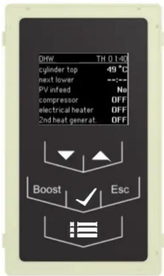
| Key Name Description | ||
| Menu Switches to the main menu, where detailed set-tings for the heat pump can be made. | ||
| Boos t | Quick heating Heating element is activated and works for a maximum of 4 hours to the domestic hot water set temperature | |
| Esc | ESC | Return to the previous menu level |
 | OK | Beginning and completion of a parameter change / selection of a desired menu item |
 | UP | Value change upwards, or selection menu and parameters |
 | DOWN | Value change downwards, or selection menu and parameters |
7.1.2 Description ready display
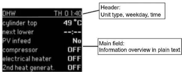
7.2 Menu structure
Parameter change: The menu is accessed using the "Menu" key. In this menu, changes can be made to parameters. The desired menu item is selected with the arrow keys "UP" "DOWN". The submenu is accessed using the "OK" key.
In this submenu, the parameter that is to be changed can be selected (also using the arrow keys). The "OK" key is used to select the marked value, which can then be changed via the arrow keys. The entry is completed by pressing the "OK" key again.
| Menu block | Menu item | Parameter | Value | Description |
| Settings | ||||
| Time | 00:00 | Time setting (24 hour time display) | ||
| Date | DD:MM:YYYY | Date setting (Day:Month:Year) | ||
| DEUTSCHENGLISHFRANCAISITALIANOPOLSKI | Language selection | |||
| Language | ||||
| OnOff | Setting key tone on / off | |||
| Backlight | 0% ... 50% ...100% | Setting display backlight | ||
| Factory setting | Factory setting reset | |||
| Type | DHW 400+ | Domestic water heat pump DHW 400+with additional heat exchanger | ||
| Domestic hot water | ||||
| Set temperature | 25°C ... 45°C ... 85°C | Sets the desired domestic hot water set temperature | ||
| Lower | 15°C ... 25°C ... 40°C | Sets the minimum hot water temperature, which should also not be undershot for the duration of a programmed lower process. | ||
| Hysteresis | 2K ... 3K ... 10K | Sets the switching hysteresis | ||
| ECO | ECO: Only switches in the event of an error and with PV b./t., thermal disinfection on | |||
| Electric heater | Mode | AUTO | ||
| Delay | 2h ... 8h...16h | |||
| Boost period | 1h ... 4h ... 8h | Boost: adjustable time (once, regardless of the Auto/Eco setting)Boost: adjustable set temperature | ||
| Boost set temp. | 25°C ... 60°C ... 85°C | |||
| Time programs | ||||
| Therm. disinfection | Thermal disinfection | |||
| Start | 00:00 ... 23:59 | Sets the start time for thermal disinfection (24 hour time display) | ||
| Days | Mo ... Su | Sets the day on which thermal disinfection should be activated | ||
| Set value | 60°C ... 65°C ... 85°C | Sets the set temperature for thermal disinfection. | ||
| 1st lower | ||||
| Start | 00:00 ... 23:59 | Sets the start time for lowering the domestic hot water set temper-ature | ||
| End | 00:00 ... 23:59 | Sets the end time for lowering the domestic hot water set tempera-ture | ||
| Days | Su ... MoMo - FrSa - SuMo - Su | Sets the weekday / block of days on which the lower should be acti-vated | ||
| 2nd lower | ||||
| Start | 00:00 ... 23:59 | Sets the start time for lowering the domestic hot water set temper-ature | ||
| End | 00:00 ... 23:59 | Sets the end time for lowering the domestic hot water set tempera-ture | ||
| Days | Su ... MoMo - FrSa - SuMo - Su | Sets the weekday / blockof days on which the lower should be acti-vated | ||
| Solar | ||||
| Selection | OffBivalentSol | Choice of additional heat sourceOff: (no add. heat source)Bivalent: 2nd heat generator, e.g. oil, gas or wood boilerSol: Thermal solar energy system | ||
| Switch-on difference | 6 K ... 8 K ... 10 K | Sets the temperature difference between the collector and cylinder temperature at which the solar pump should be switched on | ||
| Switch-off difference | 2 K ... 4 K ... 6 K | Sets the temperature difference between the collector and cylinder temperature at which the solar pump should be switched off | ||
| Max. cylinder temp. | 60 °C ... 65 °C ... 85 °C | Sets the maximum cylinder temperature that is permissible when solar gain is available | ||
| Max. collector temp. | 125 °C ... 130 °C ... 135 °C | Sets the maximum permissible temperature on the collector | ||
| 2nd heat generator | ||||
| Selection | OffBivalentSol | Choice of additional heat sourceOff: (no add. heat source)Bivalent: 2nd heat generator, e.g. oil, gas or wood boilerSol: Thermal solar energy system | ||
| Bivalence temperature | -8 °C ... 10 °C ... 15 °C | Limit temperature for the 2nd heat generator. The heat pump is blocked below this temperature | ||
| Photovoltaic | ||||
| Electric heater | YesNo | Activates the electric heater (parallel to the heat pump) in photovoltaic mode | ||
| Set temperature | 35 °C ... 45 °C ... 60 °C | Entry of the domestic hot water setpoint, which is active when photovoltaic inlet is connected. The increased setpoint is also active if the air intake temperature does not allow the heat pump to operate. In this case, the request is processed with the electric heating element or, where present, the 2nd heat generator. | ||
| Information | ||||
| Operating status | Cylinder top Display of the cylinder temperature top (R3) | |||
| Cylinder bottom Display of the cylinder temperature bottom (R5) | ||||
| Air inlet Display of the air temperature (R1) | ||||
| Collector temp. Display of the collector temperature (R13 only on models with additional heat exchanger and Sol selected as 2nd heat generator) | ||||
| Current setpoint Displays the current domestic hot water setpoint | ||||
| Defrost sensor Display the defrost (only on models with defrost) | ||||
| Fan Shows the switching status of the fan | ||||
| Compressor Shows the switching status of the compressor | ||||
| Electric heater Shows the switching status of the electric heater | ||||
| Power Shows the calculated power consumption of the device | ||||
| Operating mode Displays the current operating mode | ||||
| Runtimes | Unit Displays the operating hours | |||
| Fan Shows the runtime of the fan | ||||
| Compressor Shows the runtime of the compressor | ||||
| Electric heater Shows the runtime of the electric heater | ||||
| Soft. vers. | Shows the software version | |||
| Hardware | Shows the hardware version | |||
| Serial number | Shows the serial number | |||
| Service | ||||
| Enter password | Password-protected area for after-sales service | |||
| Messages | ||||
| Alarms | Displays the alarms, frequency and type | |||
| (start screen during first commissioning) | ||||
| Basic settings | ||||
| Language | Sets the language | |||
| Date | Sets the current date | |||
| Time | Sets the current time | |||
| Set temperature | Sets the desired domestic hot water temperature | |||
| Lower | Sets the reduced domestic hot water temperature | |||
7.3 Functions
7.3.1 Time programs
Lower
It is possible to block the operation of the domestic water heat pump by setting lower times. Two independent lower times can be programmed. The individual lower times are activated as soon as the hour or minute value is not equal to zero. During the lower times, the cylinder is kept at the lower temperature. The solar thermal and rapid heating functions, and the function for using electricity from PV systems and boost (quick heating) are possible during shut-off times.
Preventative thermal disinfection
The start time for preventative thermal disinfection and the desired setpoint must be set. The function is activated as soon as the hour or minute value is not equal to zero.
Both the heat pump and the electric heater are switched on from the start to achieve the set temperature. This ensures that the required setpoint can be reached as quickly as possible
NOTE
If the set temperature is not reached within 4 hours, the preventative thermal disinfection is terminated. The set start time can be activated every weekday. Preventative thermal disinfection should not be started after 8pm to ensure that the four hours required are available.
7.3.2 Electric heater
The integrated electric heater can be used to supplement heat pump operation. The electric heater is automatically switched on if the domestic hot water set temperature is not reached within the set delay time in heat pump operation. In ECO mode, the electric heater is only requested if the operating ranges of the heat pump are left and no 2nd heat generator is present. This is the case, for example, when the air intake temperature is undershot/exceeded. With the "Boost" key, the domestic hot water preparation can be supported with the electric heater for an adjustable period of time.
If the air temperature is above +7°C, the electric heater is blocked. It can only be switched on manually above the +7°C limit for the boost (rapid heating) function.
7.3.3 Second heat generator
An existing heat generator can be used to heat the cylinder using the integrated tube heat exchanger (1 m ^2 ). The use of a 2nd heat generator must be activated in the menu. It is requested if the heat pump's operating limits are exceeded. This is the case when the bottom or top air intake limit or the domestic hot water setpoint lies above the achievable temperature during heat pump operation (e.g. preventative thermal disinfection). In this case, the 2nd heat generator has priority over the electric heater in the heat pump. When the 2nd heat generator is activated, it is additionally possible to select a bivalence temperature which deviates from the lower operating limit (air temperature). If this temperature is undershot, heat pump operation is blocked as soon as the set temperature is reached, and the 2nd heat generator is then used.
A circulating pump is required for charging the cylinder via the additional heat exchanger, which should be operated where necessary. There are two possible solutions for this:
Activating a circulating pump for using the heat exchanger through existing domestic hot water heat pump regulation
This version is recommended if a constant heat source is present, e.g. wood heating buffer tank when using the 2nd heat generator.
The circulating pump is connected on terminal X4:
Activating a circulating pump for using the heat exchanger through existing boiler controller
We recommend this version if, in addition to the circulating pump, a boiler also has to be switched on to generate the heat. In this case, a sensor of the existing boiler controller is usually required in the heat pump cylinder. The existing sensor must be connected electrically and remain physically in the unit. To do this, stow it rolled up in the insulation in the electric heater area and reduce the setpoints in the menu where necessary. The figure below shows the position of the sensor R5 to be replaced, which is connected electrically to the external boiler controller. Recommended depth of the sensor in the pipe approx. 550 mm.
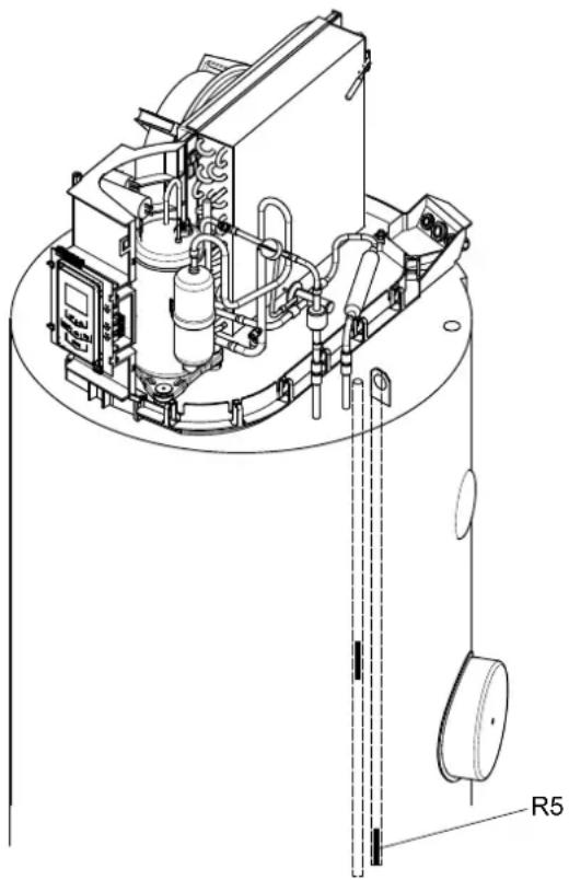
natural_image
Technical line drawing of a mechanical device with internal components and a labeled part R5 (no text or symbols beyond label)Installation position of the external temperature sensor for bivalent operation
(device cover removed in illustration)
7.3.4 Solar thermal function
As an alternative to using a 2nd heat generator, the domestic hot water heat pump can be operated in combination with a thermal solar installation. As soon as a sufficient solar yield is detected, it is used for domestic hot water preparation and the heat pump is blocked. The hystereses can be set in the menu. The circulating pump is switched off again when a solar gain is no longer available or when a temperature limit value is exceeded, either on the collector or in the cylinder. The solar thermal function has priority over heat pump operation and the electric heater.
CAUTION!
The collector sensor must be a temperature sensor with the resistance characteristic curve of a PT1000 (see Cap. 2.4.2 on pag. 4).
7.3.5 Photovoltaic function
For the photovoltaic function, the terminal X8 must be fed with 230 V 50 Hz. The evaluation unit (e.g. inverter checker) measures the output that is currently available. If the photovoltaic input is active, the heat pump controls to the setpoint for the PV mode. 1 kW can be used as a setting reference point for the power threshold in the inverter checker of the photovoltaic plants during PV operation without electric heater (700 W power consumption heat pump plus base load of the household). If the device is to work permanently with the electric heater in PV operation, a setting reference point of 2.5 kW is advisable (2200 W power consumption heat pump incl. electric heater, plus base load of the building). The solar thermal function has priority over the photovoltaic function. The display shows that the heat pump is being operated using electricity from the photovoltaic installation.
NOTE
The domestic hot water set temperature in photovoltaic mode should be set to max. 55 °C to guarantee efficient operation of the heat pump.
8 Maintenance / repair
CAUTION!
Disconnect the power supply before opening the domestic hot water heat pump; possible fan coasting must be considered.
General
The domestic hot water heat pump is extremely low maintenance. Furthermore, a one-off visual inspection for possible leaks in the water system and clogging of the condensate drain must be carried out a few days after commissioning.
The refrigeration circuit of the heat pump does not require maintenance.
Only use a damp cloth with a little soap solution to clean the domestic hot water heat pump.
8.1 Water circuit / condensate drain
The water circuit check is limited to filters that may have been installed on site and possible leakages. Dirty water filters should be cleaned and, if necessary, replaced. The seal valve in the end of the condensate hose must only be checked for contamination, and cleaned if necessary.
8.2 Air circuit supply
Maintenance work is limited to cleaning the evaporator on a regular basis and as required.
CAUTION!
Risk of injury caused by sharp-edged fins. Fins must not be deformed or damaged!
If air filters are used, they should be regularly checked for contamination and be cleaned and replaced if required.
CAUTION!
The device must be de-energised before it can be opened.
CAUTION!
The terminal X8 can also be energized when the heat pump is in switched-off state
8.3 Corrosion protection anode
The corrosion protection anode (Fig. 8.1) installed in the domestic hot water cylinder should be electrically checked on a regular basis, at least every two years after commissioning, and be replaced if necessary. Electrical checking is carried out by means of a suitable ammeter, without draining the cylinder.
Procedure:
1) Unplug the PE cable from the protection anode tab.
2) Connect the ammeter (0 to 50 mA) between the PE cable and the tab.
3) Evaluation of wear on the protection anode:
Measured value > 1 mA ⇒ protection anode is in working order.
Measured value < 1 mA protection anode must be tested and/or replaced.
If electrical testing does not provide any clear results, a visual inspection of the protection anode by a technician is recommended.
Should replacement of the protection anode [by a technician] be necessary, the cylinder must be drained via the drain valve provided (to be fitted during installation - see Appendix).
NOTE
Malfunctioning protection anodes reduce the service life of the device!
(Electrically insulated magnesium anode with selenium complying with DIN 4753 part 6)
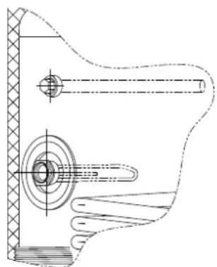
natural_image
Technical line drawing of a mechanical assembly with shaft, pulley, and housing (no text or symbols)Fig. 8.1: Anode electric heater
9 Faults / troubleshooting (for the user)
CAUTION!
Work on the domestic hot water heat pump is to be performed by qualified personnel only!
Observe accident prevention regulations!
Check the following:
■ the plug is plugged in
■ stand-by mode has been selected on the keyboard
■ the socket is supplied with voltage
■ the air inlet temperature or ambient temperature is ≥ 7 °C
■ the domestic hot water temperature is less than 60 °C
The heat pump switches off prematurely (set temperature has not yet been reached)
Check the following:
■ air ducts have been bent or their openings have been sealed, or whether any air filters are heavily contaminated (clogged).
Condensate cannot drain properly (there is water under the device)
Check the following:
The seal valve in the end of the condensate hose is contaminated or clogged, and clean if necessary; the valve can be easily removed and replaced.
■ the inflow and outflow of air is significantly reduced (bent air duct / clogged air filter).
If the above suggestions cannot help you eliminate these faults, please contact your technician or after-sales service partner.
10 Decommissioning
Tasks to be carried out:
- Disconnect the domestic hot water heat pump from the power supply.
- Completely shut off the water circuit (domestic hot water, cold water and circulation pipe) and drain the domestic hot water cylinder.
11 Environmental requirements
During maintenance or decommissioning of the domestic hot water heat pump, all environmental requirements regarding recovery, recycling and disposal of materials and components must be observed in compliance with DIN EN 378.
12 Device information
| 1 Type and order code | DHW 400+ | |
| 2 Design | ||
| 2.1 Number of units 1 | ||
| 2.2 Heat source Air | ||
| 2.3 Defrosting no | ||
| 2.4 Nominal cylinder volume litre 385 | ||
| 2.5 Transfer area of the internal heat exchanger m | 2 | 1.35 |
| 2.6 Sensor pipe _internal for external sensors mm | 9 | |
| 2.7 Installation location Frost-free | ||
| 2.8 Cylinder material | Enamelled steel complying with DIN 4753 | |
| 2.9 Cylinder insulation | PU with foil cladding | |
| 2.10 Nominal cylinder pressure | bar | 6 |
| 3 Operating limits | ||
| 3.1 Heat source operating limit ^1 | °C | 7 to 35 |
| 3.2 Domestic hot water setting range in heat pump operation | °C | 20 to 60 ^± 1.0 K |
| 4 Flow / sound | ||
| 4.1 Air flow | m ^3 /h | 325 |
| 4.2 External compression max. | Pa | 80 |
| 4.3 Air duct connection length max. | m | 10 |
| 4.4 Sound power level | dB(A) | 60 |
| 4.5 Sound pressure level ^2 | dB(A) | 50 |
| 5 Dimension/weight and filling quantities | ||
| 5.1 Dimensions height (min.) x width x depth | mm | 2043 x 740 x 776 |
| 5.2 Air duct connection diameter /normal width with EPP-ventilating pipe | mm | 190 / DN160 |
| 5.3 Weight (empty) | kg 132 | |
| 5.4 Refrigerant R 134a/total filling weight | kg | 0.95 |
| 5.5 GWP value / CO _2 equivalent | --- / t | 1430 / 1 |
| 5.6 Refrigeration circuit hermetically sealed | yes | |
| 6 Electrical connection | ||
| 6.1 Degree of protection | IP 21 | |
| 6.2 Connection voltage | 1/N/PE~230 V, 50 Hz | |
| 6.3 Connecting cable approx. 2.7 m - 1.5 mm ^2 | With plug | |
| 6.4 Fuse max. | A C16 | |
| 6.5 Power consumption heat pump cos φ | 0.8 | |
| 6.6 Supplementary electrical heating power consumption | A | 6.5 |
| 6.7 Power consumption max. | A | 9.5 |
| 6.8 Switch-on current max. | A | 13.5 |
| 6.9 Heat pump nominal power consumption at 60 °C ^3 | W | 505 |
| 6.10 Supplementary electrical heating power consumption | W | 1500 |
| 6.11 Power consumption of fan | W | 30 |
| 6.12 Total power consumption max. | W | 2200 |
| 7 Hydraulic connection | ||
| 7.1 Circulation pipe connection | R 3/4 | |
| 7.2 Domestic hot water outlet connection | R1 | |
| 7.3 Cold water inlet connection | R1 | |
| 7.4 Internal heat exchanger connection | Rp1 | |
| 8 Performance values | |||
| 8.1 Heat-up time34 | h:min | 13:15 | |
| 8.2 Energy consumption during heat-up time34 | kWh | 5.8 | |
| 8.3 Power consumption during stand-by period45 | W | 41 | |
| 8.4 Daily electricity consumption Q_elec according to EN 16147 cycle XL45 | kWh | 7.480 | |
| 8.5 COP according to EN 16147 cycle XL45 | 3.3 | ||
| 8.6 Reference domestic hot water temperature45 | °C | 55.8 | |
| 8.7 Maximum usable domestic hot water quantity45 | litres | 580 | |
| 8.8 Load profile45 | XXL | ||
| 8.9 Water heating energy efficiency _wh 45 | % | 132 | |
- At temperatures below 7 ^ ± 1 ^ , the heating element switches on automatically and the heat pump module switches off.
- At a distance of 1m (free-standing installation or installation without exhaust air duct or 90° pipe bends on outlet side).
- Heating up of nominal volume from 10 °C to 56 °C at air intake temperature of 20 °C and humidity of 60 %
- The information is valid for a new device with clean heat exchangers
- At an air intake temperature of 20 °C and 60 % relative humidity.
Table des matières
natural_image
Technical line drawing of a device with red X-shaped crosshair overlay (no text or symbols)ATTENTION!
natural_image
Technical line drawing of a mechanical device with labeled components (no readable text or symbols)natural_image
Technical line drawing of a mechanical assembly with no visible text or symbolshttps://glendimplex.de/dhw400plus

F-67590 Schweighouse Sur Moder
T+33 3 88 07 18 00
F +33 3 88 07 18 01
dimplex-ST@dimplex.de
www.dimplex.de/fr
Verkauf und Planung
Projektierung
- Installation and Operating Instruction
- Table of contents
- Please read immediately....EN-2
- Description......EN-3
- Storage and transport......EN-5
- Installation....EN-6
- Assembly....EN-7
- Commissioning......EN-8
- Operation and function of the domestic hot water heat pump......EN-8
- Maintenance / repair......EN-13
- Faults / troubleshooting (for the user)...... EN-14
- Decommissioning ...... EN-14
- Environmental requirements...... EN-14
- Device information ...... EN-15
- Anhang · Appendix · Annexes ...... A-I
- Please read immediately
- Important notes
- CAUTION!
- Intended use
- Regulations / safety information
- Descripti
- General
- The electric heater fulfils the following functions:
- ■ Supplementary heating
- Operating limit
- Emergency heating
- ■ Preventative thermal disinfection
- ■ Reheating
- NOTE
- Refrigerant circuit (heat pump operating principle)
- Safety and control devices
- High pressure switch (HP)
- Safety temperature limiter for electric heater (STL)
- Heat pump temperature controller
- Air intake temperature
- Temperature sensor
- Temperature sensor installation position
- Measured values temperature sensor
- Storage and transport
- General
- Fork lift (or lift truck) transport
- Manual transport (factory default)
- Transport in carrier (accessory with locking plate)
- Opening the device
- Installation
- Installation location
- Installation location criteria:
- Installation
- Assembly
- Connecting the water pipes
- Circulation pipe
- Connecting the condensate pipe
- Electrical connection
- Air duct connection (optional)
- Commissioning
- Domestic hot water system
- Domestic hot water system requirements
- Commissioning the domestic hot water system
- Operation and function of the domestic hot water heat pump
- Operation and display
- Description of the key functions
- Description ready display
- Menu structure
- Functions
- Time programs
- Lower
- Preventative thermal disinfection
- Electric heater
- Second heat generator
- Activating a circulating pump for using the heat exchanger through existing domestic hot water heat pump regulation
- Activating a circulating pump for using the heat exchanger through existing boiler controller
- Solar thermal function
- Photovoltaic function
- Maintenance / repair
- General
- Water circuit / condensate drain
- Air circuit supply
- Corrosion protection anode
- Procedure:
- Faults / troubleshooting (for the user)
- The heat pump switches off prematurely (set temperature has not yet been reached)
- Condensate cannot drain properly (there is water under the device)
- Decommissioning
- Tasks to be carried out:
- Environmental requirements
- Table des matières
- ATTENTION!
- Verkauf und Planung
- Projektierung
Brand : DIMPLEX
Model : DHW 400+
Category : Heat pump