DHW 250P - Heat pump DIMPLEX - Free user manual and instructions
Find the device manual for free DHW 250P DIMPLEX in PDF.


| Product type | Heat pump for domestic hot water (thermodynamic water heater) |
| Tank volume | 250 liters |
| Dimensions (diameter × height) | 630 × 1,721 mm |
| Empty weight | 82 kg |
| Operating weight (tank filled) | Approximately 335 kg |
| Electrical supply | 230 V / 50 Hz / 8 A (single-phase) |
| Recommended circuit breaker | 13 A (curve D) with 30 mA residual current device |
| Maximum combined power (heat pump + electric backup) | 1,900 W |
| Heat pump power consumption (max.) | 700 W |
| Electric backup heating power | 1,200 W (safety at 85 °C) |
| Domestic hot water temperature (heat pump mode) | 40 to 60 °C (adjustable) |
| Maximum water temperature (backup + Turbo) | 70 °C |
| Allowable air temperature range (ambient air) | 5 to 35 °C |
| Sound pressure level (at 1 m) | 37 dB(A) |
| Refrigerant | R290 (propane) – 0.150 kg – flammable |
| GWP (global warming potential) | 0.45 kg CO₂ |
| COP (coefficient of performance) according to EN 96947 | 3.2 |
| Energy efficiency class | A+ |
| Maximum tank operating pressure | 0.6 MPa (6 bar) |
| Cold water/hot water connection diameter | 3/4 inch |
| Main functions | Turbo (quick heating), Smart (adaptive), Comfort, Protect (anti-legionella), Electric (back-up mode), Off-peak hours |
| Maintenance and cleaning | Annual by a professional: cleaning of the evaporator, checking of condensate, verification of electrical connections |
| Safety | Frost protection, safety thermostat (85 °C), pressure limiter, automatic shutdown in case of fault |
Frequently Asked Questions - DHW 250P DIMPLEX
User questions about DHW 250P DIMPLEX
0 question about this device. Answer the ones you know or ask your own.
Ask a new question about this device
Download the instructions for your Heat pump in PDF format for free! Find your manual DHW 250P - DIMPLEX and take your electronic device back in hand. On this page are published all the documents necessary for the use of your device. DHW 250P by DIMPLEX.
USER MANUAL DHW 250P DIMPLEX
natural_image
Silhouettes of two people interacting with a refrigerator (no text or symbols visible)natural_image
Two silhouetted figures holding a large rectangular object with a diagonal line crossing (no text or symbols)HINWEIS
natural_image
Technical diagram of a mechanical assembly with a magnified circular view showing internal components (no text or symbols)8. Anschluss
natural_image
Line drawing of a rectangular device with two circular components and a curved cable, no text or symbols present9. Inbetriebnahme
HINWEIS
Installation and Operating Instructions
English
natural_image
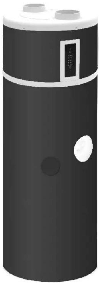
3D rendering of a cylindrical industrial device with two top ports and a control panel (no visible text or symbols)Domestic hot water heat pump
Content
Warnings 4
Operating panel 6
Scope of supply 7
Storage 7
Transport 7
Unpacking 7
Installation location 8
Connection 9
Commissioning 12
Operation 13
Maintenance 14
Faults 15
Technical data 19
1. Warnings
1.1. Intended use
This2device2is2only2intended2for2use2as2specified2by2the2
manufacturer.2-ny2other2use2beyond2that2intended2by2
the2manufacturer2is2prohibited.2This2requires2the2user2!
to2abide2by2the2relevant2project2planning2documents.
Please2refrain2from2tampering2with2or2altering2the2de-
vice.
1.2. Important information
ATTENTION!
Read2these2installation2and2operating2instructions2before2commissioning32
ATTENTION!
Work2on2the2domestic2hot2water2heat2pump is2to2be2performed2by2qualified2personnel2 only32Observe2accident2prevention2regulations3
ATTENTION!
The2device2cover2cannot2be2used2for2carryin (the2cover2cannot2withstand2significant2 forces).
ATTENTION!
Once2the2heat2pump2has2been2set2up,2the2guard2plate2must2be2removed3
ATTENTION!
The2heat2pump2may2only2be2transported2in2upright2position2(see2chapter2"Transport").
ATTENTION!
When2installing2the2on-site2pipework,2ensure2that2the2pipes2are2not2contaminated2(flush2 pipes2before2connecting2the2domestic2hot2 water2heat2pump2if2necessary).
ATTENTION!
The2domestic2hot2water2heat2pump2must2only2be2operated2when2filled2with2water.
ATTENTION!
Disconnect2the2power2supply2before2opening2the2domestic2hot2water2heat2pump02possible2fan2coasting2must2be2considered.
ATTENTION!
Risk2of2injury2caused2by2sharp-edged2fins.2 Fins2must2not2be2deformed2or2damaged3
2! ATTENTION!
Disconnect2the2power2supply2before2opening2the2device.
1.3. Regulations / safety notes
ATTENTION!
Read2these2installation2and2operating2instructions2before2commissioning3
The2domestic2hot2water2heat2pump2is2used2exclusively2to2heat2water2for2domestic2use2and2drinking2water2within2the2specified2operating2temperature2limits.2The2heating2of2fluids2other2than2domestic2water2is2not2permitted.2Technical2regulations2for2domestic2water2installation2are2to2be2observed.2The2nominal2pipe2widths2for2the2on-site2sanitary2installation2must2be2determined2taking2into2account2the2building-specific2requirements2and2the2valid2directives2and2regulations.2ng12necessary2safety2devices,2such2as2pressure2reducing2valves,2must2be2installed2according2to2the2specific2requirements.
The2following2are2not2permitted:
■ Operating2the2pump2with2solvent-based2or2explosive2exhaust2air
■ The2use2of2exhaust2air2containing2grease,2dust2or2aerosols
■ Connecting2extractor2hoods2to2the2ventilation2system
2t2is2not2permissible2to2install2the2device:
Outdoors
In2rooms2which2are2exposed2to2frost
■ In2rooms2subject2to2high2humidity2(e.g.2bathrooms)
In2rooms2with2air2which2is2potentially2explosive2because2of2gases,2vapours2or2dust
It2is2not2permissible2to2operate2the2device
■ With2an2empty2cylinder
■ During2the2construction2phase2of2the2building
The2construction2and2design2of2the2domestic2hot2water2heat2pump2complies2with2the2relevant2EU2directives.
The specialist technician must ensure that the refrigerant is flushed adequately to allow maintenance and repair work to be carried out on refrigerant circuit components without risk. Refrigerant must be properly handled and disposed of; it must not be released into the environment! The refrigeration circuit is "hermetically sealed" and contains the refrigerant R290. Information on the ^2 WP value and CO _2 equivalent of the refrigerant is available under "Device information". The refrigerant is CFC-free, non-ozone depleting and combustible.
Always disconnect the power supply before carrying out any work on the domestic hot water heat pump.
When connecting the domestic hot water heat pump to the power supply, the relevant country-specific standards must be complied with. Also observe the technical connection requirements of the electrical utility companies.
This heat pump is designed for use in a domestic environment according to Article 1, Paragraph 2 k) of EU directive 2006/42/EC (Machinery Directive) and is thus subject to the requirements of EU directive 2014/35/EU (Low Voltage Directive).
ATTENTION!
Work on the domestic hot water heat pump is to be performed by qualified personnel only!
2. Operating panel
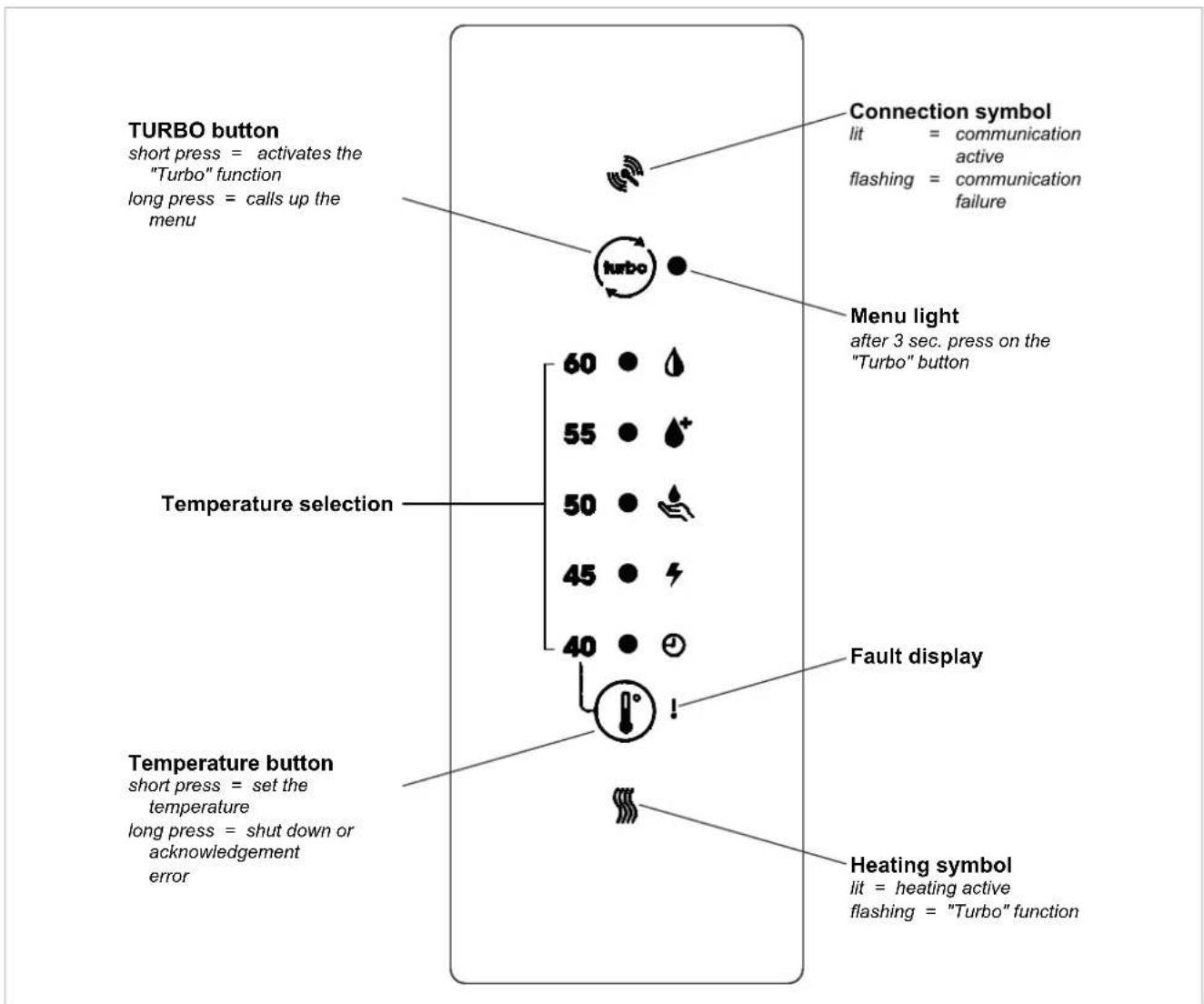
flowchart
graph TD
    A["TURBO button\nshort press = activates the "Turbo" function\nlong press = calls up the menu"] --> B["Connection symbol\nlit = communication active\nflashing = communication failure"]
    B --> C["Menu light\nafter 3 sec. press on the "Turbo" button"]
    C --> D["Temperature selection"]
    D --> E["60 ● ↓"]
    D --> F["55 ● ↓"]
    D --> G["50 ● ↓"]
    D --> H["45 ● ↓"]
    D --> I["40 ● ↓"]
    D --> J["Fault display"]
    J --> K["Temperature button\nshort press = set the temperature\nlong press = shut down or acknowledgement error"]
    K --> L["Heating symbol\nlit = heating active\nflashing = "Turbo" function"]
3. Scope of supply
■ 1 Domestic hot water heat pump
■ 1 Documentation pouch with the following contents:
- 1 Installation instructions
- 1 Operating instructions
4. Storage

NOTE
The permissible transport and storage temperature of the domestic hot water heat pump is between -5 °C and +35 °C.
5. Transport

NOTE
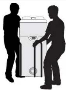
The cover of the domestic hot water heat pump may not be used as a transport aid!
Permissible transport position:
natural_image
Silhouette of two people interacting with a large appliance (no text or symbols visible)Impermissible transport position:
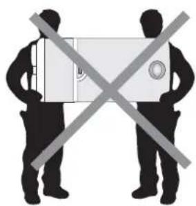
natural_image
Two silhouetted figures holding a rectangular object with a diagonal line crossing (no text or symbols)
NOTE
All other transport positions are prohibited.

NOTE
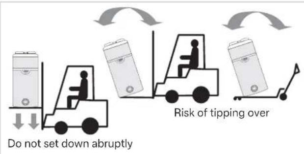
Transporting the device in horizontal position may permanently destroy the components of the heat pump.

NOTE
Risk of tipping over! Centre of gravity moved upwards. Handle with care!

NOTE
After installing the domestic hot water heat pump in its final installation location, wait 15 minutes before commissioning.
6. Unpacking
Pull off the plastic cover and cardboard packaging. Remove the edge protection, ensuring that no nails and clips are pulled out.
Remove the protective film from all parts of the device and remove the documentation pouch in the transport bag.
Use a suitable tool to loosen the transport screw under the pallet.

NOTE
Plastic bags and the transport bag should be kept away from small children.
There is a risk of suffocation.
7. Installation location
7.1. Selecting the installation location
ATTENTION!
Take the following into account during installation: The device must not be installed close to a constant flame or other ignition source. The device must be installed so that mechanical damage is avoided.
It is forbidden to install the device as follows:
■ outdoors,
■ in rooms with exposure to frost or with a temperature below 7 °C, even if the device is in operation,
■ in extremely humid rooms with high steam levels (e.g. bathrooms),
■ in rooms where there is a risk of explosion due to the presence of gases, vapours or dust.
■ Installation close to bedrooms should be avoided to guarantee comfortable noise levels.
It is forbidden to
■ operate the device with intake air containing solvents or potentially explosive substances,
■ use intake air containing grease, dust or aerosols,
■ connect extraction hoods to the ventilation system,
■ use air containing boiler combustion products.
7.2. Arrangement and fixing
To guarantee that the domestic hot water heat pump works normally and to make maintenance work easier, a minimum distance around the device and a minimum ceiling height for removing the device cover must be observed.
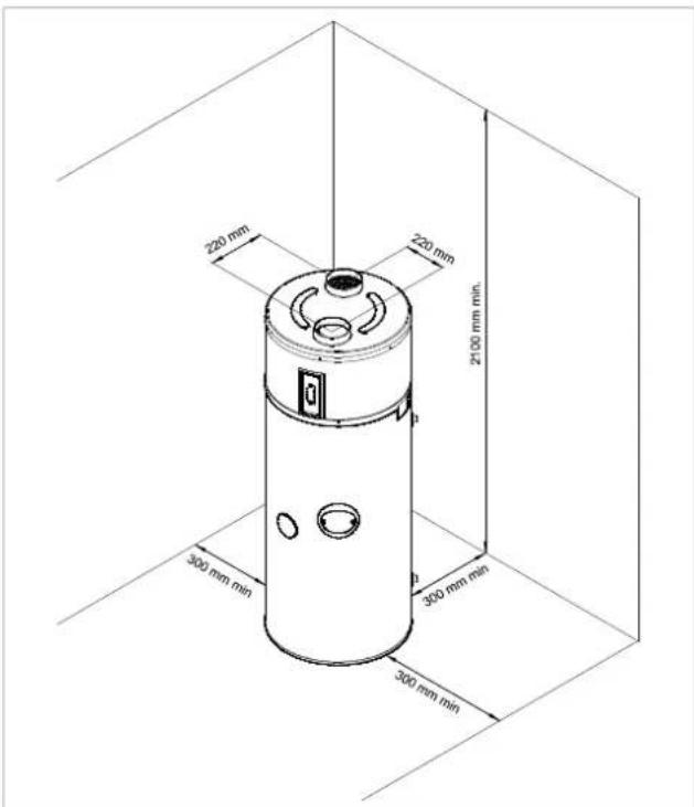
The floor must have an adequate load bearing capacity (weight of the domestic hot water heat pump, filled with 250 l water = 335 kg).
NOTE
The domestic hot water heat pump must be installed vertically. Otherwise, condensate may overflow, causing water to accumulate on the floor.
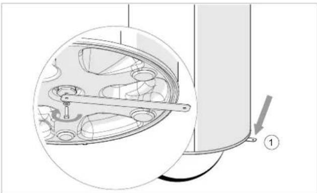
Use the fixing point to fix the cylinder on the floor and fix the device via the metal tongue with a ∅ M8 screw that can be dowelled on to the floor (see 1).
natural_image
Technical diagram of a mechanical assembly with a circular inset showing internal components (no text or symbols)8. Connection
8.1. Air-technical connection
The device is designed for use without an air duct. When using an air duct for intake, a total length of 2 m with a maximum of two 90° elbows is permitted. Failure to observe these regulations will void the manufacturer warranty
Without an air duct, the device must be installed in an unheated room (at least 20 m ^4 ) separate from neighbouring heated rooms.
If the clear height under the ceiling over the device is less than 60 cm, it is advisable to install an elbow on the air outlet and to direct it to the rear or to the sides.
The domestic hot water heat pump can also be used in unheated workshops and garages if the parameters listed in chapter 7 are complied with.
The domestic hot water heat pump enables dehumidification and cooling of rooms such as laundry rooms and storerooms.
8.2. Connecting the water pipes
A new safety group (not included in the scope of supply) must be installed that is set to 6 bar on the cold water inlet of the device. We recommend installing a safety assembly.
This safety group must correspond to the national standards and comply with DIN 1988, Part 2; DIN 4753, Part 1 and DIN EN 1488.
The safety group must be mounted as close as possible to the cold water inlet of the device and the water flow must never be obstructed by an accessory (valve, pressure reducer etc.)
The drainage outlet of the safety group must be installed in a frost-free environment and have a downward slope.
The drainage outlet of the safety group must be designed according to the standard and must never be blocked. It must be connected via a funnel (at least 20 mm to free air) to a vertical outlet line with a diameter that corresponds at least to that of the connection line of the device.
If the pressure on the cold water inlet is more than 5 bar, a pressure reducing valve must be installed upstream of the safety group on the flow.
We recommend mounting an isolation valve before the safety group.
For systems
■ with pipes with a small diameter,
■ with a ceramic ball cock
valves must be installed as close as possible to the cocks, or an expansion vessel adapted to the system, to prevent pressure surges.
Connection diagram
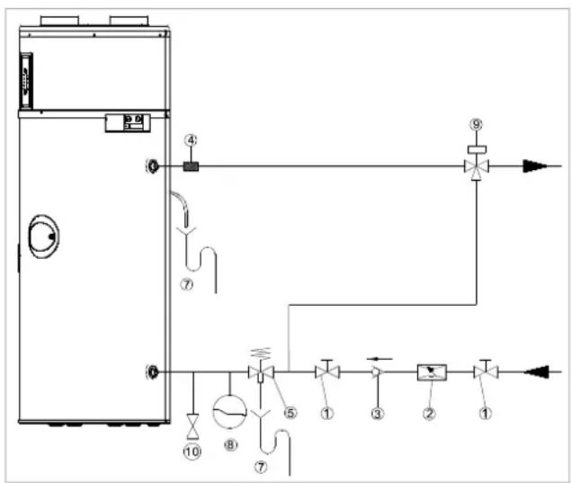
flowchart
graph TD
    A["Control Unit"] --> B["Valve ④"]
    B --> C["Sensor ⑦"]
    C --> D["Flow Control Valve ⑤"]
    D --> E["Sensor ⑧"]
    E --> F["Sensor ⑨"]
    F --> G["Output"]
    style A fill:#f9f,stroke:#333
    style B fill:#ccf,stroke:#333
    style C fill:#cfc,stroke:#333
    style D fill:#fcc,stroke:#333
    style E fill:#cff,stroke:#333
    style F fill:#ffc,stroke:#333
    style G fill:#fcf,stroke:#333
1 Isolation valve
2 Pressure reducing valve
3 Check valve
4 Dielectric insulation sleeve, optional (not included in the scope of supply)
5 Safety assembly (SVK 825)
(not included in the scope of supply)
7 Siphon drain
8 Expansion vessel
9 Thermostatic mixer
10 Drain valve
The following materials must be used for the domestic hot water circuit:
Copper
■ Stainless steel
Brass
Plastic
NOTE
Depending on the materials used for the domestic hot water circuit, corrosion-related damage may occur due to incompatibilities.
For this reason, connection of the device to copper domestic hot water lines must be carried out with a cast or steel connection or using dielectric connections (not included in the scope of supply), which prevent any galvanic bridge (iron/copper).
The supply line upstream of the device connection to the sanitary installation must be flushed well so that no metal parts or other foreign bodies are transported into the device.
The standards applicable at the installation location must be complied with in particular with regard to the sanitary conditions and the pressure safety conditions.

NOTE
The maximum value of the domestic hot water temperature must not exceed 60 °C at the tapping points. Suitable thermostatic mixer taps must be installed to rule out any risk of scalding.
The device works with water with a total hardness between 6.5 °dH and 17 °dH. For particularly hard water (total hardness >14 °dH), we recommend using a water softener.
Failure to observe the conditions outlined above will void the warranty for the use of the cylinder (the values apply for a water temperature of 20 °C ).
| Specific resistance 2200 V.cm < R < 4500 V.cm | ||
| Water hardness >1.6 I eq. | >4.5 °dH | |
| Free CO2 <15 mg/l - | ||
| Calcium (Ca++) | >1.6 I eq. >4.5 °dH | |
| Sulphate (SO4--) | <2 I eq. >5.6 °dH | |
| Chloride (Cl-) <2 I eq. >5.6 °dH | ||
| Sulphate and chloride (SO4-- + Cl) | <3 I eq. >5.6 °dH | |

NOTE
We strongly advise against using a circulation line. This device is not designed for this type of connection. A circulation connection will result in a significant temperature drop in the cylinder.

NOTE
We are unable to honour a warranty if these points have not been observed or if a correct procedure could not be observed in line with the legislation due to the water quality.
8.3. Condensate drain
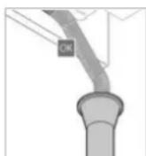
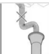
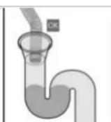
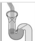
The condensate hose must not be connected directly to the drain. It must end in the free air in a siphon, which must be mounted and filled with water.
Do not fit a sleeve connection.
Do not bend the hose.
8.4. Electrical connection

NOTE
Do not connect the domestic hot water heat pump to the electric line of an old water heater that is connected to the contact for peak and low load times.

NOTE
Continuous voltage must be applied on the domestic hot water heat pump. The control of the peak and low load times takes place via a cable to be installed separately Earthing is essential here.
The supply takes place mono-phase with 230 V (1/N/PE 230 V \~, 50/60 Hz).
The power supply must be compliant with the regulations valid in the installation country and with the standard NFC 15-100.
A separating device must be installed on fixed lines in accordance with the installation regulations, which can guarantee a complete shutdown under the conditions of category III
The device must be protected as follows:
■ with an all-pole circuit breaker 13 A with
■ contact opening of at least 3 mm,
■ with a circuit breaker 13 A with differential 30 mA.
If the supply line is damaged, it must be replaced by the manufacturer, the manufacturer's after-sales service or a person with comparable qualification to avoid damage.
Circuit diagram
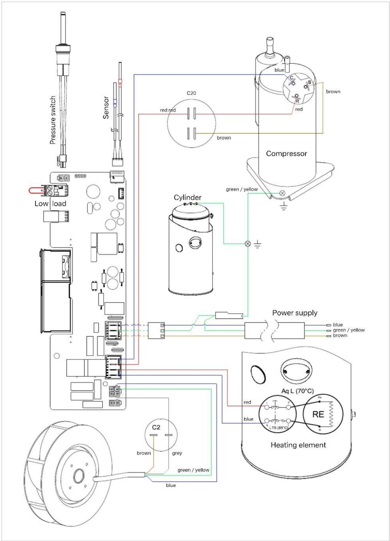
External control
NOTE
An external connection must be floating. Otherwise, there is a risk that the electrical components may be destroyed. Failure to observe these instructions will void any warranty claims.
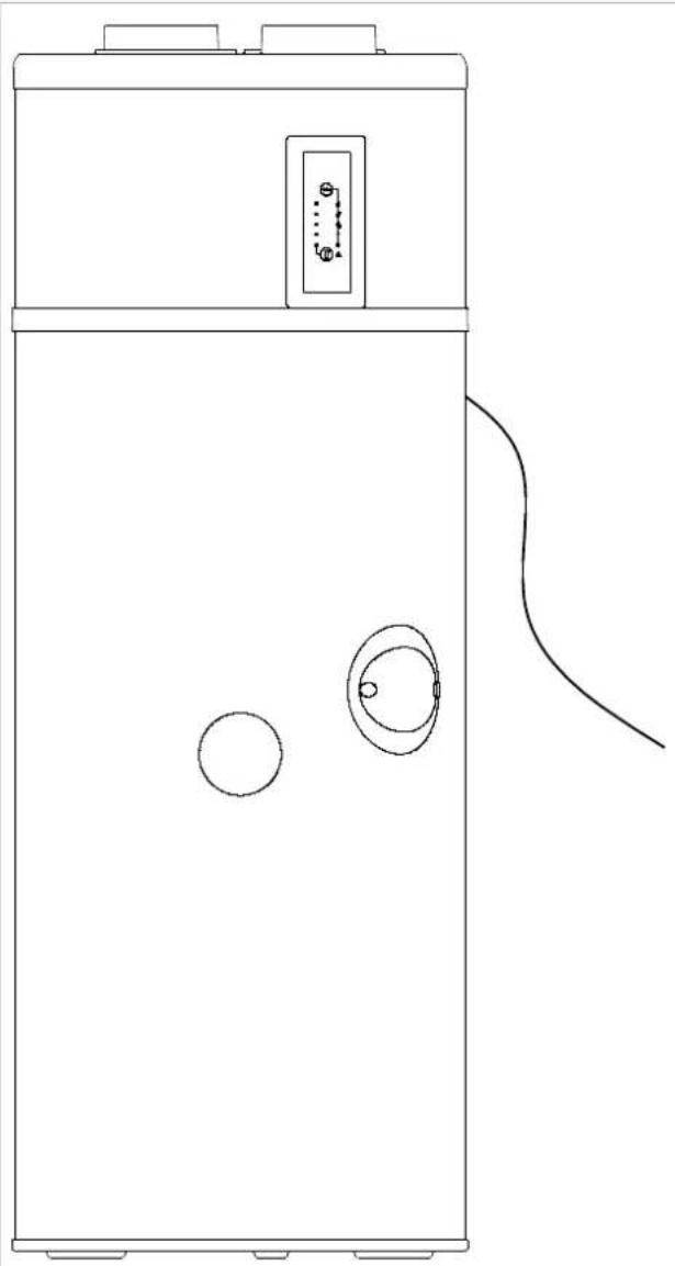
For access to the electrical connections:
■ Remove the cover of the device and remove the fixing screw on the bottom flange for this purpose.
■ Remove the protective cover of the electronic board.
natural_image
Line drawing of a rectangular device with two circular components and a curved cable, no text or symbols present9. Commissioning
NOTE
High risk of damage: Fill the cylinder before commissioning and connection to the mains.
NOTE
Before commissioning, check the entire water circuit for leaks.
■ Leave the device switched off.
■ Open the top domestic hot water tapping point of the system.
■ Open the cold water inlet on the safety group.
■ Fill the cylinder until the water runs from the top tapping point free from bubbles.
■ Close the domestic hot water tapping point.
In the permissible range between +5 °C and +45 °C intake air temperature, the device is primarily in heat pump operation.
The domestic hot water temperature supplied by the heat pump can be controlled up to 60 °C.
For a high domestic hot water consumption, the domestic hot water heat pump has a so-called "Comfort" function ⚠With this function, the heat output is increased if only 1/3 of the remaining cylinder volume is above temperatures >38 °C.
If a large quantity of domestic hot water is required for a short time, the domestic hot water heat pump has a "Turbo" function (can be activated by the user), which heats up the water quickly to the desired temperature using the supplementary electric heating (e.g. to 50 °C). This function is deactivated again as soon as the setpoint is reached (e.g. 50 °C).
10. Operation
10.1. Operation/standby
Press briefly to switch on the device.
A long press switches the device to standby mode.
The product continues to maintain frost protection in standby mode.
Setting the temperature
Pressing the button briefly and repeatedly adjusts the temperature.
NOTE
For optimal use of the heat pump, we recommend ensuring that the setpoint selected for the water temperature is not too high if the requirement is not high. The water temperature is set to 55 °C as standard.
After a few seconds without being used, the display switches off (active mode) with the exception of the display light for heating.
Simply pressing one of the buttons or activates the display again for reading the current setpoint.
10.2. Activating the "Turbo" function
Pressing the button activates the Turbo function, the heating symbol flashes.
NOTE
The "Turbo" function activates the heat pump and the electric heating element at the same time. This speeds up the heat-up process in a heating cycle.
The heating symbol flashes to indicate the activation of the "Turbo" function.
10.3. Menu
Pressing and holding the ⏻ button activates the menu.
Pressing the ⏻ button briefly switches between the following functions:
- "Smart" function (manages the heating depending on the estimated domestic hot water consumption)
- - "Comfort" function (use of the supplementary heating during periods of high water consumption)
- "Protect" function (activation of a weekly cycle for combating legionella)
- "Electric" function (for operation with supplementary electric heating only)
- "Low load times" function (for operation only in the event of a signal at low load times)
Pressing the button briefly activates (LED on) or deactivates (LED off) the selected function.
"Smart" function
With the "Smart" function, it is possible to only maintain part of the cylinder at the temperature if the device detects a lower hot water consumption.
ATTENTION!
We recommend only activating this function once you have familiarised yourself with the demand and the actual hot water consumption.
We advise against activating the "Smart" function and the "External control" function at the same time.
"Comfort" function
The "Comfort" function enables the supplementary electric heating to be operated at the same time as the heat pump. This is designed to prevent the water temperature from falling below a minimum comfort temperature of 38 °C.
The supplementary electric heating is active until the water temperature rises to max. 43 °C in this case. It then switches off and the heat pump ends the complete heating of the domestic water.
When the "Low load times" function is activated, the "Comfort" function is deactivated during "peak load times" (external contact open).
"Protect" function
During the anti-legionella heat-up, the water is heated to a temperature of >60 ^ by the heat pump.
If the setpoint for the domestic hot water is already set to 60 °C, no cycle for combating legionella is initiated, as this takes place permanently.
If a cycle is interrupted by a period where operation is forbidden (utility company blocking signal or another external contact), it is started again in the next release period.
"Electric" function
If the "Electric" function is activated, the device only uses the electric heating element for heating the water.
This means that emergency operation is necessary if the heat pump can not be used (e.g. air lines still to be connected, dust-generating work close to the device etc.).
"Low load times" function ⏻
The water heater may only be operated if the external contact is closed.
If the contact is open, the product is switched off completely, except in the following cases:
■ Frost protection
■ "Turbo" function
11. Maintenance
11.1. General
To maintain the performance and improve the service life of the device, we recommend having annual inspection and maintenance work carried out by an authorised specialist.
NOTE
Any form of intervention on the domestic hot water heat pump may only be carried out by qualified personnel.
NOTE
Observe the safety regulations!
NOTE
Any intervention in the refrigeration circuit may only be carried out by qualified personnel with a refrigeration certificate in at least category 1.
NOTE
It is forbidden to release refrigerant into the atmosphere.
NOTE
The refrigerant must be collected before any intervention in the circuit.
NOTE
De-energize the domestic hot water heat pump before opening.
NOTE
Wait until the fan has stopped completely before any intervention.
NOTE
No water may reach electrical components.
NOTE
The efficiency of the pressure limiter must be checked regularly to remove any limescale deposits and to ensure that it is not blocked.
When emptying the cylinder, ensure that there is sufficient rear ventilation (e.g. cylinder cover, domestic hot water outlet) to avoid any vacuum in the cylinder. The following materials and products may not be used:
■ Brushes with steel bristles and steel sponges,
■ scouring powder.
■ any product based on sodium or potassium hypochlorite solution or other chlorine derivatives.
During maintenance work or when decommissioning the domestic hot water heat pump, observe the environmental protection regulations with regard to collecting, recycling and disposing of used materials and components.
NOTE
The R290 refrigerant in the heat pump circuit poses no risk to the environment, but is flammable.
NOTE
The R290 refrigerant is odourless.
NOTE
The pipes of the refrigeration circuit must not be damaged.
NOTE
Do not work with open flame or other ignition sources within the device.
NOTE
In the event of a refrigerant leak, disconnect the plug, ventilate the room and contact after-sales service.
NOTE
To not use mechanical means of speeding up the defrost process.
NOTE
Do not pierce or burn the device. It is essential that the refrigerant is caught and collected during any intervention in the refrigeration circuit.
When carrying out interventions in the refrigeration circuit, proceed as follows:
- Secure the work area.
■ Inform the affected persons of the risks associated with the work being carried out.
■ Ensure that the risk of ignition is low. - Avoid working in enclosed, narrow spaces. The work area must be adequately ventilated.
- Check the work area before and during the work with a suitable leak detector.
- Keep a dry powder or CO _2 extinguisher close to the work area.
11.2. Water circuit and condensate drain
Check that the condensate drain is working correctly. Proceed as follows:
■ Remove the hood (see procedure in the chapter "External control").
■ Ensure that the outlet opening for the condensate is not blocked.
■ Clean the condensate collection container (above the cylinder). Deposits from the intake air may collect here.
■ Clean the drain hose.
■ The efficiency of the pressure limiter must be checked regularly to remove any limescale deposits and to ensure that it is not blocked.
- Check the leak-tightness of the hydraulic connections on the domestic hot water heat pump.
11.3. Supply and exhaust air
The maintenance work is restricted to the cleaning of the evaporator (at least once a year depending on the cleanliness of the intake air).
If air filters are used, their soiling level must be checked regularly. Clean the filters and replace as required.
Risk of injury on sharp edged fan blades! The fan blades must be neither deformed nor damaged.
11.4. Electrical maintenance
Regular checks must be carried out to determine whether the electronic power board and the electrical terminal strips of the components listed below are clean and free from dust deposits:
- compressor,
■ heating element,
condensers.
The correct seating of all cable lugs must also be checked. The frequency of the checks must be adapted to the air quality: More frequent maintenance is required in dusty environments and maintenance must be carried a least once a year whatever the conditions.
NOTE
If the electronic board and the electrical components are not cleaned for a long time, this could act as an ignition source for fire.
12. Faults
12.1. Eliminating faults
The heat pump is not working
■ The setpoint is higher than the water temperature in the cylinder.
■ The device is supplied correctly with power.
■ The temperature of the intake air or the ambient temperature is not below 5 °C or above 45 °C.
■ The device is not blocked by a signal at peak load times.
■ A fault is shown on the display (see chapter "Fault messages").
No domestic hot water
■ The consumption is not above the saved volume.
■ The external control (low load/peak load times) does not restrict the function to an excessively short time frame.
■ The programmed water temperature is not too low.
The condensate cannot flow away 8there is water under the device)
■ The condensate drain is not soiled or blocked. Clean if necessary. Proceed as follows:
- Remove the hood (see procedure in the chapter "External control").
- Check the inlet from the condensate collection container to the condensate drain hose.
■ The hose is not kinked and is routed downwards.
■ The hose ends in free air in a line.
■ The cylinder is set up correctly (vertically).
The supplementary electric heating is not working
■ The function is not blocked by an external contact.
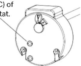
The safety thermostat for the supplementary electric heating was not triggered due to overtemperature (>85 °C). If this is the case, reset the thermostat.
- Check the following before carrying out the reset:
- The heating element is not covered with limescale.
- Clean the heating element and replace if necessary.
Reset button (85 °C) of the safety thermostat.
NOTE
Do not change the setting of the limiting switch (Aq- uastat).
12.2. Fault messages
| Display Type of fault Cause Measures required | Temporary function /Wait for problem to be solved | |||
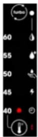 | Domestic hot water sensor of the cylinder faulty. | Domestic hot water sensor out of order.Domestic hot water sensor not connected to the board.Sensor line damaged | Replacement of the domestic hot water sensor. | Heat pump off (or working at half power in "Smart" function) |
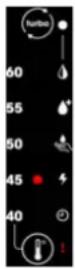 | Room temperature sensor faulty. | Room temperature sensor out of order.Room temperature sensor not connected to the board.Sensor line damaged | Replacement of the room temperature sensor. | Heat pump is off.Supplementary electric heating system heats up the water to 43 °C (min. 38 °C). |
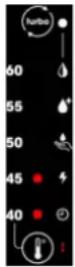 | "Smart" sensor faulty (for the affected models). | Domestic hot water sensor out of order.Domestic hot water sensor not connected to the board.Sensor line damaged | Replacement of the domestic hot water sensor. | "Smart" function deactivated. |
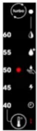 | High pressure on the heat pump. | No water in the cylinder.Water too hot (>75 °C).Domestic hot water sensor pulled out of the cylinder.Domestic hot water sensor faulty | Check whether the cylinder is filled correctly with water.Replace the domestic hot water sensor.Check whether the domestic hot water sensor is sitting correctly in the immersion sleeve. | Heat pump is off.The reset takes place automatically.Operation of the supplementary heating possible. |
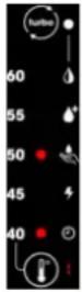 | Overtemperature of the cylinder. | No water in the cylinder.Water too hot (>75 °C).Domestic hot water sensor pulled out of the cylinder.Domestic hot water sensor faulty | Check whether the cylinder is filled correctly with water.Replace the domestic hot water sensor.Check whether the domestic hot water sensor is sitting correctly in the immersion sleeve. | Heat pump is off.The reset takes place automatically.Operation of the supplementary heating possible. |
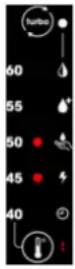 | Monitoring of the heating. | Insufficient refilling of the cylinder.Heating element failure.Domestic hot water sensor poorly positioned or faulty. | Check whether the cylinder is filled correctly with water and the air is discharged.Check whether the domestic hot water sensor in the cylinder is sitting correctly in the immersion sleeve.Measure the resistance value of the heating element. | Heat pump is off.The reset takes place automatically.Operation of the supplementary heating possible. |
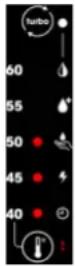 | Compressor fault. | Faulty connection of the compressor.Compressor faulty.Problem with fill level. | Check the condition of the cables.Check the fill level of the refrigerant. | Operation with supplementary electric heating. |
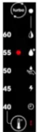 | Fault. | Lack of air flow.Cylinder installed in an area with inadequate space. | Check that the air is guided correctly through the product.Check that the minimum distances are complied with around the product.Check the condition of any connected filters or air ducts.Check that the evaporator is clean. | Operation with supplementary electric heating. |
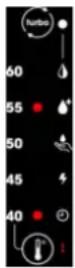 | Too frequent defrosting. Too frequent defrosting | Check that the air is guided correctly through the product.Check that the minimum distances are complied with around the product.Check the condition of any connected filters or air ducts.Check that the evaporator is clean. | Heat pump is off.Supplementary electric heating system heats up the water to 43 °C (min. 38 °C). | |
If you cannot correct the fault, please contact a specialist technician or our after-sales service.
12.3. Change
Changes on the device are prohibited. Any component replacement must be carried out by a specialist with original spare parts from the manufacturer.
12.4. Decommissioning
Temporary decommissioning of the device

NOTE
For periods of prolonged absence where the power supply in the residential unit and to the device is switched off, the device must be emptied with the help of a qualified specialist and protected from frost.
Permanent decommissioning of the device

NOTE
The device must be decommissioned by a specialist technician.
12.5. Disposal

ATTENTION!
The device must be de-energized before decommissioning and disassembly.

ATTENTION!
The storage heater may only be disassembled by a qualified specialist.
These devices are free from asbestos and can be completely dismantled without concerns.
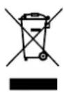
The device must not be disposed of as household waste, but must be taken to a local disposal point.
Please store removed domestic hot water heat pumps in a dry place throughout the
entire disposal chain, as trace elements may otherwise enter the groundwater.
Disposal of refrigerant

NOTE
The device contains the refrigerant R290 (propane).

NOTE
The refrigerant must always be disposed of by a specialist.

NOTE
Observe the general safety regulations.
12.6. Drainage
■ Disconnect the device from the power supply.
- Close the cock on the cold water inlet of the safety group. Ensure that the air supply (rear ventilation) is present at the highest point.
■ Open the domestic hot water cocks.
■ Bring the safety group into the draining position.
12.7. NTC sensor characteristic curve
The 4 probes have the same curve with regard to the ohmic values.
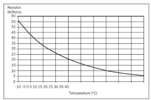
line
| Temperature (°C) | Resistor (kOhms) | | ---------------- | ---------------- | | -10 | 55 | | 0 | 45 | | 5 | 35 | | 10 | 25 | | 15 | 20 | | 20 | 15 | | 25 | 10 | | 30 | 8 | | 35 | 6 | | 40 | 5 |13. Technical data
13.1. Power heat pump
| Nominal volume I | 250 | |
| Maximum power (HP* + supplementary heater) | W | 1900 |
| Air temperature range °C | 5 to 35 °C | |
| Hot water temperature with heat pump | °C | 40 to 60°C |
| Power consumption of the heat pump, max. | W | 700 |
| Sound pressure level at 1 m** | dB(A) | 37 |
| Refrigerant - / kg | R 290 / 0.150 | |
| ^2 WP value ( CO_2 equivalent) | kg | 0.45 kg CO_2 |
| Air-technical connection type | - | Indoor air |
13.2. Standard data EN 16147
| Withdrawal cycle - | I | |
| COP* - | 3.2 | |
| Electrical reserve power W | 32 | |
| Reference domestic hot water temperature | °C | 53.8 |
| Heat-up time - | 08:00 | |
| Energy efficiency class - | A+ | |
| Seasonal energy efficiency % | 133 | |
| Vmax I | 321 | |
| V40 td | I | 713 |
13.3. Dimensions and connections
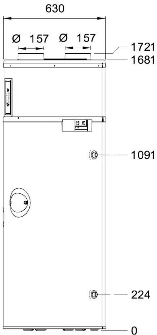
| Dimensions | mm | 630 x 1721 |
| Weight (empty) kg | 82 | |
| CW and DHW connection diameter | Inch | 3/4 |
| Power supply | V/Hz/A | 230 V/50 Hz/8 A |
| Degree of protection | - | IPX1 |
| Circuit breaker (curve D) A | 13 A | |
| Frequency range*** | MHz | 868 - 868.6 |
| HR power*** | dBm | 10.65 |
13.4. Cylinder
| Materials and protection | - | Enamelled steel |
| Operating pressure, max. | MPa | 0.6 (6 bar) |
| Condensate throughput, max. | l/h | 0.3 |
| Power integrated supplementary electric heating system (Safety = 85 °C) | W | 1200 |
| Temperature with supplement.electric heating system, max. | °C | 70 |
• DHW = domestic hot water
HP = heat pump
* CW = cold water COP = coefficient of performance
** Sound pressure tested in a low-reflection room
*** When equipped with wireless option
13.5. Dimensions
ATTENTION!
Heavy shipping weight.
^2 len Dimplex Deutschland ^2 mbH Phone: +49 9221 709 545
Am 20oldenen Feld 18 Fax: +49 9221 709 924545
95326 Kulmbach, 2ermany E-mail: service@dimplex.de
DHW 250P
DCDimplex
natural_image
3D rendering of a cylindrical industrial device with two top ports and a control panel (no visible text or symbols)Chauffe-eau thermodynamique
Contenu
Mises en garde 4
natural_image
Silhouettes of two people interacting with a washing machine (no text or symbols visible)natural_image
Two silhouetted figures holding a large rectangular object with a crossed-out X symbol (no text or symbols present)REMARQUE
natural_image
Technical diagram of a mechanical assembly with a magnified circular view showing internal components (no text or symbols)8. Raccordement
natural_image
Line drawing of a rectangular device with two circular components and a curved cable, no text or symbols present9. Mise en service
REMARQUE
natural_image
Technical line drawing of a circular mechanical component with mounting holes and a central hub (no text or symbols)REMARQUE
93.3. Dimensions et raccordements
- HINWEIS
- Anschluss
- Inbetriebnahme
- Installation and Operating Instructions
- Content
- Warnings
- Intended use
- Important information
- ATTENTION!
- 2! ATTENTION!
- Regulations / safety notes
- Operating panel
- Scope of supply
- Storage
- NOTE
- Transport
- Unpacking
- Installation location
- Selecting the installation location
- Arrangement and fixing
- Connection
- Air-technical connection
- Connecting the water pipes
- Condensate drain
- Electrical connection
- External control
- Commissioning
- Operation
- Operation/standby
- Setting the temperature
- Activating the "Turbo" function
- Menu
- "Smart" function
- "Comfort" function
- "Protect" function
- "Electric" function
- "Low load times" function ⏻
- Maintenance
- General
- Water circuit and condensate drain
- Supply and exhaust air
- Electrical maintenance
- Faults
- Eliminating faults
- The heat pump is not working
- No domestic hot water
- The condensate cannot flow away 8there is water under the device)
- The supplementary electric heating is not working
- Fault messages
- Change
- Decommissioning
- Temporary decommissioning of the device
- Permanent decommissioning of the device
- Disposal
- Disposal of refrigerant
- Drainage
- NTC sensor characteristic curve
- Technical data
- Power heat pump
- Standard data EN 16147
- Dimensions and connections
- Cylinder
- Dimensions
- DCDimplex
- Contenu
- REMARQUE
- Raccordement
- Mise en service
- Dimensions et raccordements
Brand : DIMPLEX
Model : DHW 250P
Category : Heat pump