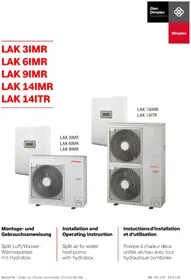
LAK 9IMR - Heat pump DIMPLEX - Free user manual and instructions
Find the device manual for free LAK 9IMR DIMPLEX in PDF.


| Product type | Air-to-water heat pump, two units, reversible |
| Brand and model | Dimplex LAK 9IMR |
| Indoor unit dimensions (H x W x D) | 694 x 450 x 240 mm |
| Outdoor unit dimensions (H x W x D) | 834 x 950 x 330 mm |
| Weight indoor/outdoor unit | 23 kg / 69 kg |
| Electrical supply - Power | 1~/N/PE 230 V, 50 Hz, fuse C25 A (compressor) + C32 A (heater) |
| Electrical supply - Control | 1~/N/PE 230 V, 50 Hz, fuse C13 A |
| Nominal heat output (Prated) | 4 kW (according to EU regulation no. 813/2013) |
| COP at A7/W35 | 4.8 (according to EN 14511) |
| Refrigerant | R410A, 1.9 kg, GWP 2088, CO₂ equivalent 4 t |
| Nominal air flow (outdoor) | 3 600 m³/h |
| Sound power level - Indoor / Outdoor | 42 dB(A) / 63 dB(A) |
| Operating temperature range (heating) | Outdoor air: -20 °C to +30 °C; Water outlet: max. 55 °C |
| Operating temperature range (cooling) | Outdoor air: +10 °C to +43 °C; Water outlet: 7 to 25 °C |
| Auxiliary electric heater | 2, 4 or 6 kW switchable (delivery state: 6 kW) |
| Protection | IP20 (indoor) / IPX4 (outdoor) |
| Safety valve opening pressure | 2.5 bar |
| Defrost type | Cycle inversion |
| Recommended maintenance | Annual check by a professional; regular cleaning of the outdoor heat exchanger with water |
| Hydraulic connections | Heating flow and return: G 1\" (external thread with flat gasket) |
Frequently Asked Questions - LAK 9IMR DIMPLEX
User questions about LAK 9IMR DIMPLEX
0 question about this device. Answer the ones you know or ask your own.
Ask a new question about this device
Download the instructions for your Heat pump in PDF format for free! Find your manual LAK 9IMR - DIMPLEX and take your electronic device back in hand. On this page are published all the documents necessary for the use of your device. LAK 9IMR by DIMPLEX.
USER MANUAL LAK 9IMR DIMPLEX
LAK 3IMR LAK 6IMR LAK 9IMR LAK 14IMR LAK 14ITR
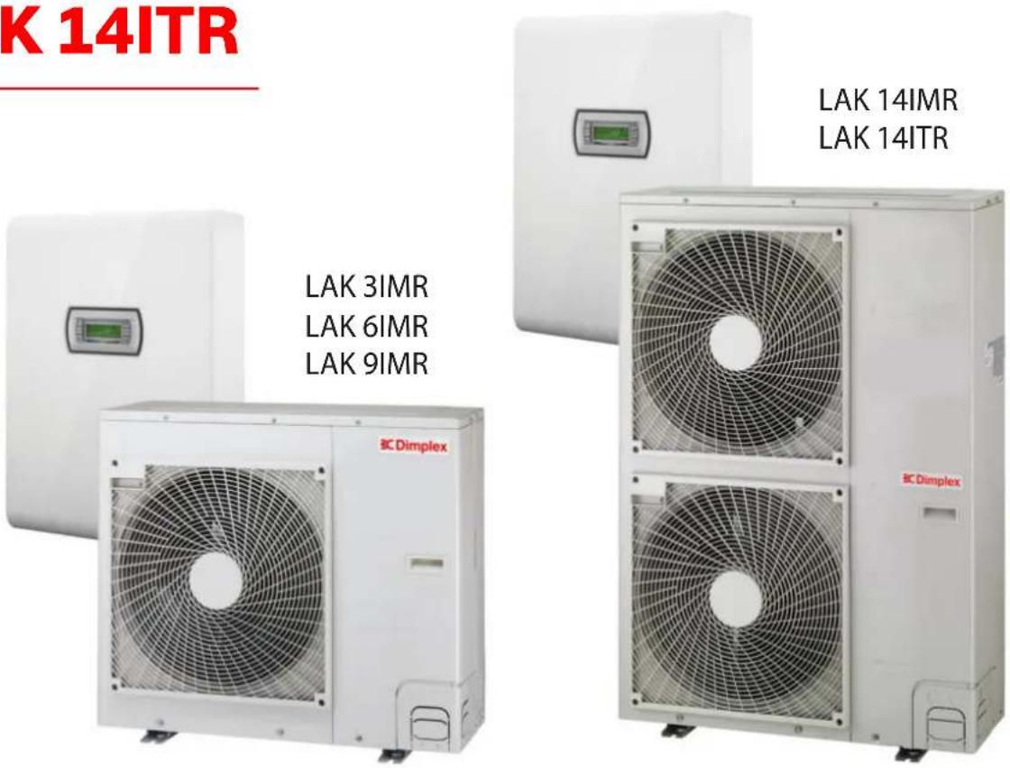
Installation and Operating Instruction
Split air-to-water heat pump with hydrobox
natural_image
Front view of a rectangular electronic device with internal components and a central display (no text or symbols visible)! ACHTUNG!
flowchart
graph TD
    A["Seewind"] --> B["Step 1"]
    B --> C["Seepage with circular icon"]
    C --> D["Step 2"]
    D --> E["Backwind with circular icon"]
1.1 Symbols and markings......EN-2
1.2 Important notes....EN-2
1.3 Intended use......EN-2
1.4 Legal regulations and guidelines ......EN-2
2 Purpose......EN-3
2.1 Area of application.....EN-3
2.2 General properties....EN-3
3 Scope of supply......EN-3
3.1 Indoor unit....EN-3
3.2 Contact plate....EN-3
3.3 Wärmepumpenmanager....EN-3
4 Outdoor unit....EN-4
4.1 Installation....EN-4
4.2 Precautions in winter and in seasonal winds....EN-6
5 Assembly indoor unit......EN-6
5.1 General.....EN-6
5.2 Indoor unit fixing....EN-6
5.3 Heating system connection....EN-7
6 Commissioning......EN-8
6.1 General......EN-8
6.2 Preparation......EN-8
6.3 Commissioning procedure....EN-8
7 Connecting the pipework and cables to the outdoor unit......EN-9
7.1 Refrigerant pipes....EN-9
7.2 Electrical connections....EN-11
7.3 Final work....EN-12
7.4 Leak test and evacuation....EN-13
8 Test points, maintenance and troubleshooting......EN-14
8.1 Checklist prior to commissioning......EN-14
8.2 Maintenance....EN-15
8.3 Troubleshooting......EN-15
8.4 Characteristic curve temperature sensor outdoor unit......EN-16
8.5 Characteristic curve temperature sensor indoor unit.....EN-16
9 Cleaning / maintenance ...... EN-17
9.1 Maintenance....EN-17
9.2 Cleaning the heating system ......EN-17
10 Faults / troubleshooting....EN-17
11 Decommissioning / disposal......EN-17
12 Device information ...... EN-18
13 Product information as per Regulation (EU) No 813/2013, Annex II, Table 2......EN-20
Anhang · Appendix · Annexes ...... A-I
Maßbilder / Dimension Drawings / Schémas cotés....A-II
Diagramme / Diagrams / Diagrammes....A-IX
1 Safety not 1.3 Intended use
1.1 Symbols and markings
Particularly important information in these instructions is marked with CAUTION! and NOTE.
CAUTION!
Immediate danger to life or danger of severe personal injury or significant damage to property.
NOTE
Risk of damage to property or minor personal injury or important information with no further risk of personal injury or damage to property.
1.2 Important notes
The operational reliability of the safety valve must be checked at regular intervals. We recommend having an annual service inspection carried out by a qualified specialist company.
The outflow from the safety valve should visibly flow into a waste water drain.
The installer of the heating system is responsible for checking whether an additional expansion vessel is required.
Operating the system in a sensible way can provide significant energy savings. The heating water temperature should be as low as required during heat pump operation. The planner of the heating system is responsible for determining the system temperature.
When installing an underfloor heating system, a sensible value for the maximum flow and return temperature should be set on the heat pump manager. The position of the temperature sensor is important in this regard.
This device is only intended for use as specified by the manufacturer. Any other use beyond that intended by the manufacturer is prohibited. This requires the user to abide by the relevant project planning documents. Please refrain from tampering with or altering the device.
1.4 Legal regulations and guidelines
This heat pump is designed for use in a domestic environment according to Article 1, Paragraph 2 k) of EU directive 2006/42/EU (machinery directive) and is thus subject to the requirements of EU directive 2014/35/EU (low-voltage directive). It is thus also intended for use by non-professionals for heating shops, offices and other similar working environments, agricultural establishments and hotels, guesthouses and other residential buildings.
The construction and design of the LWPS device complies with all relevant EU directives, DIN and VDE regulations (see CE declaration of conformity).
When connecting the LWPS device to the power supply, the relevant VDE, EN and IEC standards are to be fulfilled. Any further connection requirements stipulated by the mains supply network operator must also be observed.
The current valid regulations must be complied with when connecting the heating system. The local regulations for the drinking water supply must also be complied with when connecting the LWPS device to the drinking water supply.
This unit can be used by children aged 8 and over and by persons with limited physical, sensory or mental aptitude or lack of experience and/or knowledge, providing they are supervised or have been instructed in the safe use of the unit and understand the associated potential dangers.
Children must not play with the device. Cleaning and user maintenance must not be carried out by children without supervision.
CAUTION!
When operating or maintaining a heat pump, the legal requirements of the country where the heat pump is operated apply. Depending on the refrigerant quantity, the heat pump must be inspected for leaks at regular intervals by a certified technician, and these inspections must be recorded.
More information can be found in the accompanying log book.
2 Pur p o s e
2.1 Area of application
The indoor unit constitutes the interface between a reversible heat pump and the heating system in the building. The indoor unit contains all hydraulic components required between heat generation and heat distribution with an unmixed heating circuit.
2.2 General properties
■ Low installation effort
Ready for use
The infinitely adjustable operation of the circulating pump permits adjustment of the output according to need.
on LAK 6IMR - LAK 14ITR:
■ Switchable pipe heater (2 / 4 / 6 kW) for supplementary heating.
on LAK 3IMR:
■ with 2 kW (fixed-setpoint) pipe heating
3 Scope of supply
3.1 Indoor unit
Hydraulic components
■ Unmixed heating circuit including controlled circulating pump
■ 2nd heat generator, electrical pipe heater, heat output 2 / 4 / 6 kW, secured via safety temperature limiter
Safety equipment:
■ Safety valve, start-to-leak pressure 2.5 bar
Refrigerating equipment
■ Heat exchanger refrigerant / heating water
■ Connections for split line
NOTE
External sensor is included with the outdoor unit as standard. Option for connecting an external sensor Cap. 8.5.2 on pag. 16.
3.2 Contact plate
The cover must be removed to allow access to the inside of the device.
The two screws on the bottom must be loosened for this. The cover must then be removed to the top.
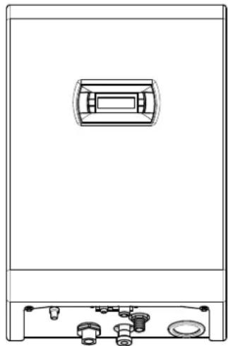
natural_image
Front view of a rectangular electronic device with internal components and a central display (no text or symbols visible)CAUTION!
Before opening the device, ensure that all circuits are disconnected from the power supply!
After removing the cover, the electronics area is freely accessible.
The contact plate contains the supply connection terminals, heating contactors, connecting terminals for the connecting line to the heat pump and the heat pump manager.
3.3 Wärmepumpenmanager
The integrated heat pump manager is a convenient electronic regulating and control device. It controls and monitors the entire heating system based on the outdoor temperature, as well as domestic hot water preparation and safety systems.
The enclosed operating instructions describe the functional principle and use of the heat pump manager.
4 Outdoor unit
4.1 Installation
It is advisable to install the outdoor unit close to a wall, on a foundation separate from the building with a minimum clearance of 0.3 m on the intake side (Fig. 4.1 + Fig. 4.2).
If a canopy is mounted to protect from direct sunlight, rain or snow it must not impede the heat exchange of the device.
In the case of a free-standing installation, the foundation is to be connected on the intake side, flush with the device. This will prevent snow from building up between the foundation and the evaporator.
The minimum clearances (Fig. 4.1) indicated must be adhered to.
When selecting an installation location, it should be ensured where possible that persons are not going to be inconvenienced by the circulation of warm/cold air or by noise emissions.
The condensate tray offers various options for the condensate drain. In warmer regions, the condensate can drain from the device freely. In regions with longer periods of frost, a controlled condensate drain is required.
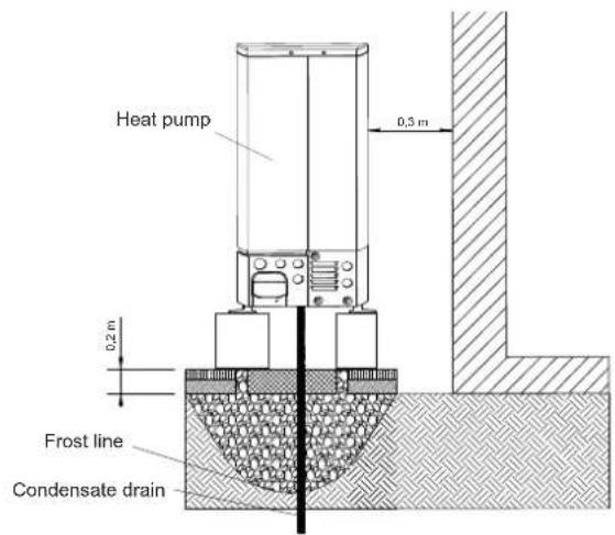
Fig. 4.1
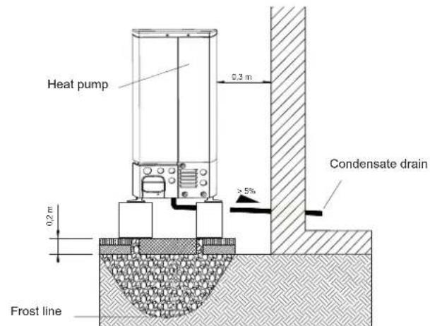
Fig. 4.2
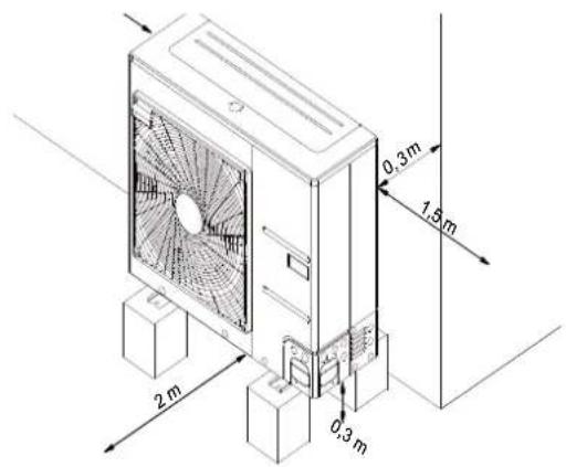
Fig. 4.3
Installation on wall brackets is not advisable, as this frequently leads to noise problems.
If this type of installation is used, observe the following instructions:
Fit rubber buffers
■ Take the weight of the outdoor unit into account
■ Ensure that the wall bracket is no higher than 1 m above the ground
■ Ensure that minimum clearances are adhered to
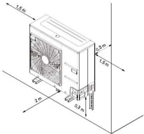
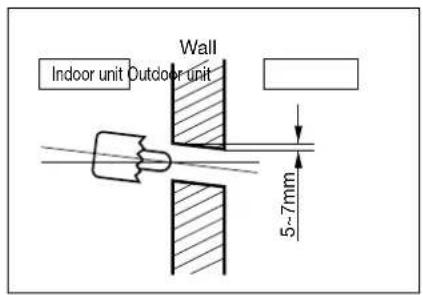
Fig. 4.4
NOTE
The heat pump is not intended for use over 2000 metres above sea level.
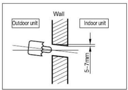
4.1.1 Wall opening for split lines and electric wires
■ Please proceed as follows when laying split lines and electric wires:
- Drill a 70 mm opening for the pipework using a core drill
The opening for the pipework should be slightly inclined towards the outdoor unit, so that no rainwater can penetrate the building.
4.1.2 Wall opening for condensate drain
4.1.3 Installation in coastal areas
NOTE
The air-to-water heat pump must NOT be installed in areas where corrosive gases such as acids or alkaline gases can occur.
NOTE
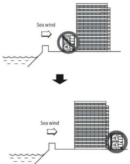
If the outdoor unit is installed in a coastal area, direct sea wind should be avoided.
Case 1: If the outdoor unit is installed in a coastal area, direct sea wind should be avoided. Install the outdoor unit in the opposite direction to the sea wind.
flowchart
graph TD
    A["Sea wind"] --> B["Dam or reservoir"]
    B --> C["Downward arrow"]
    C --> D["Sea wind"]
    D --> E["Downward arrow"]
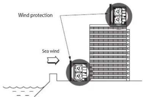
Case 2: If the outdoor unit is installed in the direction of the sea wind, set up a wind guard to catch the sea wind.
The wind guard must be robust enough to catch the sea wind (e.g. made from concrete).
The height and width of the wind guard must correspond to at least 150% of the outdoor unit.
A distance of at least 700 mm from the outdoor unit must be maintained to guarantee sufficient air flow.
flowchart
graph TD
    A["Wind protection"] --> B["Sea wind"]
    B --> C["Building with two turbines"]
    style A fill:#f9f,stroke:#333
    style B fill:#ccf,stroke:#333
    style C fill:#cfc,stroke:#333
NOTE
If the outlined requirements cannot be complied with during installation in coastal areas, please contact Dimplex employees for more information on corrosion protection.
NOTE
Dust or salt soiling on the heat exchanger should be regularly cleaned (at least once a year) with water.
4.2 Precautions in winter and in seasonal winds
In snowy areas or extremely cold locations, adequate protective measures must be taken to guarantee that the unit continues functioning correctly.
- Install the outdoor unit so that snow cannot fall directly on the unit. If snow collects on the air inlet and freezes, errors can occur. Install a cover in areas with snowfall.
When installing the outdoor unit in areas where there is a lot of snowfall, ensure the unit is installed at least as high as the level of an average snowfall (average annual snowfall).
If more than 100 mm of snow collects on the outdoor unit, the snow must be removed prior to operation.
NOTE
The intake and outlet opening of the outdoor unit should not be positioned against the wind if possible.
5 Assembly indoor unit
5.1 General
The unit should always be installed indoors on a level, smooth wall. Maintenance work can be carried out easily from the operator side (a minimum clearance at the side is not required). This can be ensured by maintaining a clearance of 1 m at the front. The indoor unit should be mounted at a height of approx. 1.30 m. It must be installed in a room protected from frost and with short pipe runs.
NOTE
Setup and installation must be performed by an authorised specialist company.
When installing the indoor unit, the load-bearing capacity of the wall should be checked. On account of the acoustics, measures for isolating possible vibrations should also be very carefully planned in advance.
The following connections need to be established on the indoor unit:
■ Flow / return of the heating system
■ Safety valve outflow
Power supply
Supply voltage
Split refrigerant pipe
Condensate drain
■ Expansion vessel connection (optional)
NOTE
When removing the unit cover, it must be taken into account that the length of the connecting cable between the control panel in the unit cover and the controller on the contact plate is only 1.5 m. If the device cover can only be placed further away than this when it has been removed, the plug connection on the controller or on the control panel must first be disconnected.
5.2 Indoor unit fixing
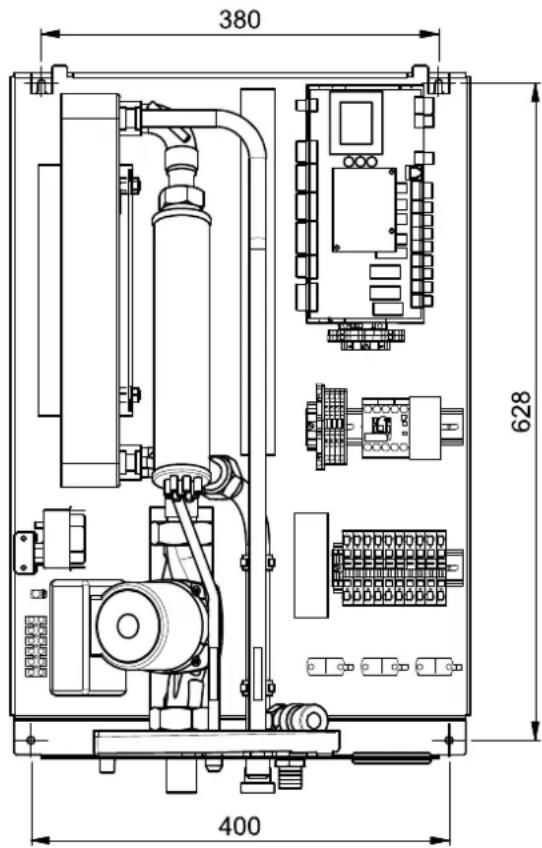
The indoor unit is attached to the wall with the screws and dowels (8 mm) included in the scope of supply. The following procedure should be used:
■ Mount the dowels for the top fastening eyelets.
- Screw the screw into the dowel so that the indoor unit can be mounted.
■ Mount the indoor unit by the upper fastening eyelets.
■ Mark the position of the side drill-holes.
■ Unhook the indoor unit again
■ Mount the dowels for the side drill holes.
5.3 Heating system connection
The heating system connections on the indoor unit have a 1" flat sealing external thread. A spanner must be used to firmly grip the transitions when making the connections.
There is a hose sleeve on the safety valve for on-site connection of a plastic hose. This should be fed into a siphon or outflow.
Before connecting the heating water system to the heat pump, the heating system must be flushed to remove any impurities, residue from sealants, etc. Any accumulation of deposits in the liquefier may cause the heat pump to completely break down. Once the heat pump has been connected to the heating system, it must be filled, purged and pressure-tested.
The following points must be observed when filling the system:
■ Untreated filling water and make-up water must be of drinking water quality
(colourless, clear, free of sediments)
■ Filling water and make-up water must be pre-filtered (max. pore size 6 m).
Scale formation in domestic hot water heating systems cannot be avoided, but in systems with flow temperatures below 60 °C, the problem can be disregarded. With high-temperature heat pumps and in particular with bivalent systems in the higher performance range (heat pump + boiler combination), flow temperatures of 60 °C and more can be achieved. The following standard values should therefore be adhered to with regard to the filling and make-up water according to VDI 2035, sheet 1: The total hardness values can be found in the table.
| Total heat output in kW | Total alkaline earths in mol/m3 and/or mmol/l | Specific system volume (VDI 2035) in l/kW | ||
| < 20 | ≥ 20 < 50 | ≥ 50 | ||
| Total hardness in °dH | ||||
| < 50 | ≤ 2.0 | ≤ 16.8 | ≤ 11.2 | < 0.111 |
| 50 - 200 ≤ 2.0 | ≤ 11.2 ≤ 8 | 4 | ||
| 200 - 600 ≤ 1.5 | ≤ 8.4 | < 0.111 | ||
| >600 | < 0.02 | < 0.111 | ||
- This value lies outside the permissible value for heat exchangers in heat pumps.
Fig. 5.1: Guideline values for filling and make-up water in accordance with VDI 2035
For systems with an above-average specific system volume of 50 l/kW, VDI 2035 recommends using fully demineralized water and a pH stabiliser to minimize the risk of corrosion in the heat pump and the heating system.
CAUTION!
With fully demineralized water, it is important to ensure that the minimum permissible pH value of 7.5 (minimum permissible value for copper) is complied with. Failure to comply with this value can result in the heat pump being destroyed.
NOTE
If the unit is connected to an existing hydraulic water circuit, the hydraulic pipes must be cleaned to remove residues and limescale.
The heating circuit must include a corresponding purging facility, a fill and drain valve and a dirt trap on-site.
It is also recommended to install a shut-off device in the return before integration into the indoor unit is carried out.
Minimum heating water flow rate
The minimum heating water flow rate must be ensured in all operating states of the heating system with at least 50 l (buffer tank with individual room control or underfloor heating system with 50 l minimum volume in open heating circuits). When the minimum heating water flow rate is undershot, the plate heat exchanger in the refrigeration circuit can freeze, which can lead to total loss of the heat pump.
NOTE
The installation of a flow rate switch (DFS LAK or VSH LAK) is absolutely necessary to ensure water flow before compressor start and during defrosting.
The nominal flow rate is specified depending on the max. flow temperature in the device information and must be taken into account during planning. With design temperatures below 30 °C in the flow, the design must be based on the max. volume flow with 5 K spread for A7/W35.
The specified nominal flow rate (See “Device information” on page 18.) must be assured in all operating states. An installed flow rate switch is used only for switching off the heat pump in the event of an unusual and abrupt drop in the heating water flow rate and not to monitor and safeguard the nominal flow rate.
Frost protection
A method of manual drainage must be provided for heat pump internal components which are exposed to frost. The frost protection function of the heat pump manager is active whenever the heat pump manager and the heat circulating pump are ready for operation. The system has to be drained if the heat pump is taken out of service or if a power failure occurs. The hydraulic network should be operated with suitable frost protection if heat pump systems are implemented in buildings where a power failure cannot be detected (vacation homes etc.).
NOTE
Chemical treatment to protect from rust should be carried out by the installer.
6 Commissioning
6.1 General
To ensure that commissioning is performed correctly, it should only be carried out by an after-sales service technician authorised by the manufacturer. This may be a condition for an additional warranty (see "Warranty service").
6.2 Preparation
The following items must be checked prior to commissioning:
All of the indoor unit connections must be installed as described in Chapter 5.1.
All of the outdoor unit connections must be installed as described in Chapter 7.
All valves which could impair the proper flow of the heating water in the heating circuit must be open.
■ The air intake and air outlet paths must be clear.
The settings of the heat pump manager must be adapted to the heating system in accordance with the manager's operating instructions.
- The heating water circuit must be completely filled and purged.
■ Ensure that the condensate drain functions properly.
■ The outflow from the heating water pressure relief valve must also function correctly.
■ Purging the heating system:
Ensure that all heating circuits are open, purge the system at the highest position and refill water if necessary (comply with static minimum pressure).
6.3 Commissioning procedure
The heat pump is commissioned via the heat pump manager. Settings should be made in compliance with the HPM's instructions.
The heating element of mono energy systems should be disconnected during commissioning.
| Heat source temperature | Max. temperature spread between heating flow and return flow | |
| by to | ||
| -20 °C -15 | °C 4 K | |
| -14 °C -10 | °C 5 K | |
| -9 °C -5 | °C | 6 K |
| -4 °C | 0 °C | 7 K |
| 1 °C | 5 °C | 8 K |
| 6 °C | 10 °C | 9 K |
| 11 °C | 15 °C | 10 K |
| 16 °C | 20 °C | 11 K |
| 21 °C | 25 °C | 12 K |
| 26 °C | 30 °C | 13 K |
| 31 °C | 35 °C | 14 K |
At heating water temperatures below 7 °C, commissioning is not possible. The water in the buffer tank must be heated with the 2nd heat generator to at least 18 °C.
The following procedure must then be followed to ensure problem-free commissioning:
1) Close all consumer circuits.
2) Ensure that the heat pump has the correct water flow.
3) Use the manager to select the automatic operating mode.
4) In the special functions menu, start the "Commissioning" program.
5) Wait until a return temperature of at least 25 °C has been reached.
6) Now slowly reopen the heating circuit valves in succession so that the heating water flow rate is constantly raised by slightly opening the respective heating circuit. The heating water temperature in the buffer tank must not be allowed to drop below 20 °C during this process. This ensures that the heat pump can be defrosted at any time.
7) When all heating circuits are fully open and a return temperature of at least 18 °C is maintained, the commissioning is complete.
CAUTION!
Operating the heat pump at low system temperatures may cause the heat pump to break down completely. After a prolonged power failure, the commissioning procedure detailed above must be followed.
7 Connecting the pipework and cables to the outdoor unit
This chapter describes the refrigerant pipe connections and the electrical cable connections on the outdoor unit.
7.1 Refrigerant pipes
CAUTION!
Work on the system must only be performed by authorised and qualified after-sales service technicians!
Certain requirements with regard to pipe length and rise must be complied with when installing refrigerant pipes. Once all requirements have been fulfilled, certain preparations must be made.
Once these are complete, the connecting pipe from the outdoor unit to the indoor unit can be connected.
7.1.1 Requirements for pipe length and rise
| Model | Pipe size (mm)(diameter: ) | Length A (m) Rise B (m) | *additional refrigerant(g/m) | |||||
| Gas | Liquid | Normal | Min. | Max. | Normal | Max. | ||
| 3 kW | 12(1/2") | 6(1/4") | 7.5 | 2 | 25 | 0 | 15 | 15 |
| 6 kW9 kW | 15.88(5/8") | 9.52(3/8") | 7.5 | 3 | 50 | 0 | 30 | 30 |
| 14 kW | 15.88(5/8") | 9.52(3/8") | 7.5 | 3 | 50 | 0 | 30 | 60 |
The standard pipe length is 7.5 m. Up to a length of 15 m, no additional refrigerant filling is required. For pipe lengths over 15 m, the system must be filled with additional refrigerant in accordance with the table.
*Example: When installing the 14 kW model at a distance of 50 m, 2100 g refrigerant must be added according to the following calculation: (50-15) x 60 g = 2100 g
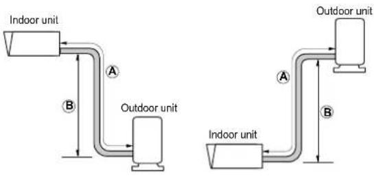
NOTE
If the indoor unit is mounted 4 or more metres higher than the outdoor unit, a cooling technology specialist must perform a separate check to ensure that the devices for conveying the oil up and down the pipes have been installed correctly in the hot gas pipe.
NOTE
The rated output of the device corresponds to the standard pipe length and the maximum possible length.
CAUTION!
Incorrect filling with refrigerant could lead to faults during operation.
1) Production operation (see model name label)
2) Installation operation (where possible, attach alongside the maintenance connections for adding or removing refrigerant)
3) Total filling (1, + 2,)
7.1.2 Preparation for pipework
The preparation of the pipework takes place in five steps. One main cause of refrigerant leaks is incorrect flanging. Flanging must be carried out carefully and according to the following steps.
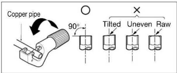
Step 1: Cutting pipes and cables
■ Use the installation kit for pipework or the pipes purchased from your local dealer.
■ Measure the distance between the indoor and outdoor unit.
- Cut the pipes slightly longer than the measured distance.
Step 2: Removing burrs
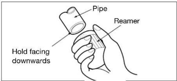
■ Remove all burrs from the interface of the pipework.
- Hold the pipe end downwards so that no burrs can fall into the pipe.
Step 3: Inserting screw nuts
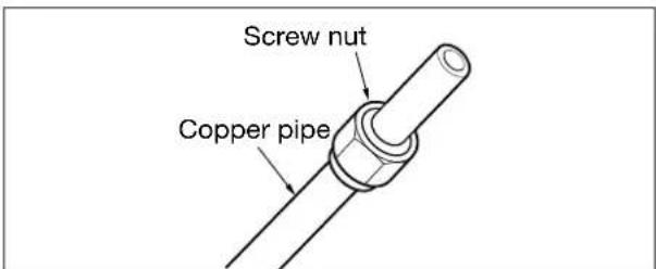
■ Remove the screw nuts on the indoor and outdoor unit.
■ Insert the screw nuts into the deburred pipe.
No nuts can be inserted into the pipe after flanging.
Step 4: Flanging
■ Flanging must be carried out as follows with a flanging tool for R-410A refrigerant as shown in the figure.
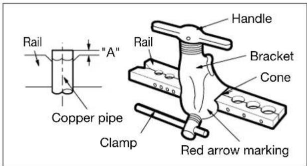
| External diameter "A" | ||
| mm Inch mm | ||
| 9.52 3/8 1.5 ~ | 1.7 | |
| 15.88 5/8 1.6 ~ | 1.8 | |
- Hold the copper pipe steady in a mould with the dimensions shown in the bottom table.
Step 5: Checks
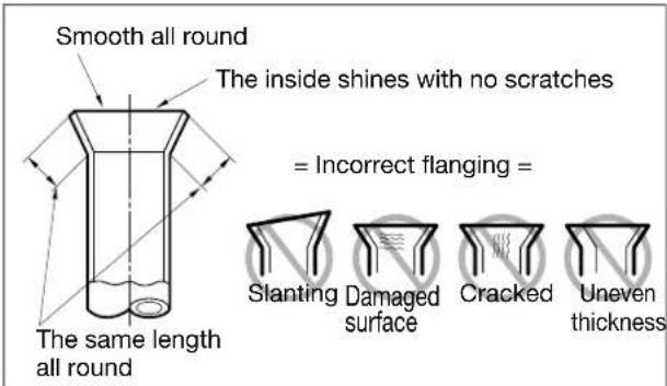
■ Compare the flanging with the figure on the right.
If the flanging is visibly damaged, cut the relevant section off and repeat the flanging.
7.1.3 Pipe connections on the indoor unit
The pipe connection on the indoor unit takes place in two steps. Read the following instructions carefully.
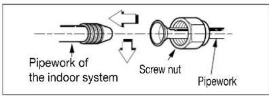
Step 1: Initial fastening
- Align the centre of the pipe and tighten the screw nuts by hand.
Step 2: Fastening
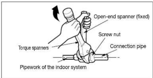
■ Tighten the screw nuts with a spanner.
Torques
| External diameter Torque | ||
| mm Inch Nm | ||
| 9.52 3/8 34 - 42 | ||
| 15.88 5/8 65 - 81 | ||
7.1.4 Pipe connections on the outdoor unit
The pipe connection on the outdoor unit takes place in steps.
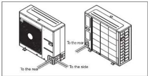
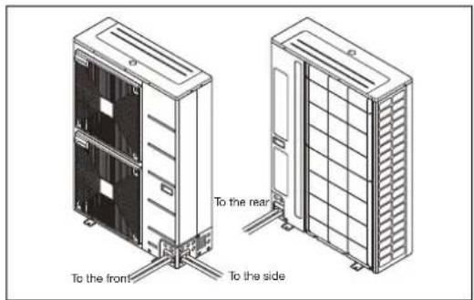
Step 1: Determining the direction in which the pipes are to run
■ The pipes can be connected in four directions
Step 2: Fastening
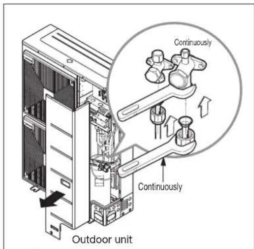
- Align the centre of the pipe and tighten the screw nuts by hand.
■ Tighten the screw nuts with a spanner until they click.
Torques.
Step 3: Preventing foreign bodies from entering the unit
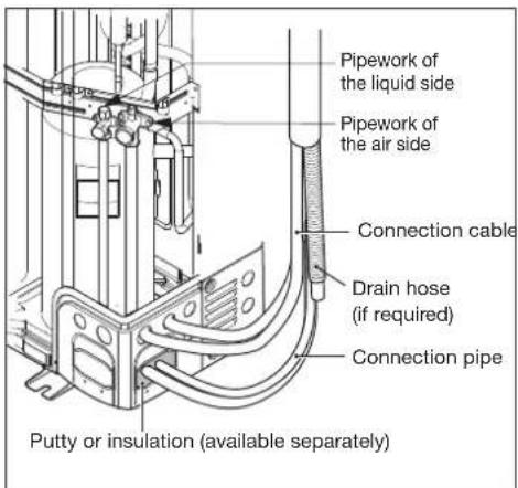
Seal all pipe openings well with putty or a different type of insulation (available separately).
If insects or small animals enter the outdoor unit, they can cause short circuits in the control cabinet.
Lay the pipes. To do this, cover the coupling device of the indoor unit with insulation and fix in place with two adhesive tapes.
■ Adequate heat insulation is extremely important.
CAUTION!
Never open the valves of the outdoor component. Carry out the work from Cap. 7.2 on pag. 11 and Cap. 7.3 on pag. 12 first of all.
7.2 Electrical connections
7.2.1 Outdoor unit
NOTE
The DIP switches on the circuit boards in the outdoor unit have no function. The positions of the DIP switches must remain in their factory default and must not be changed!
Two cables must be connected on the outdoor unit:
A 'mains cable' and a 'data cable'
Both cables must be laid between the indoor and outdoor unit. The mains cable is used to supply the outdoor unit with power and the data cable is for communication between the outdoor and indoor component. The VDE directives and regulations and local conditions must be taken into account in the design and installation of the two cables.
The indoor component already contains a safeguard element for the outdoor component. The safeguarding of the entire heat pump must also take place externally.
For LAK 3IMR, LAK 6IMR, LAK 9IMR, LAK 14IMR:
The mains cable on the outdoor unit must be three-core and must be connected to the L / N / PE (power supply) terminals. (See Cap. 3.2 on page XII; Cap. 3.5 on page XV and Cap. 3.8 on page XVIII)
For LAK 14ITR
The mains cable on the outdoor unit must be 5-core and must be connected to the R / S / T / N / PE terminals (see Cap. 3.5 on page XV)
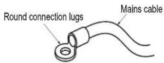
If no connection lugs are available, proceed as follows.
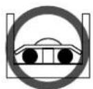
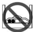
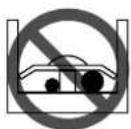
No cables with different thicknesses may be connected to the connecting terminal. (one of the cables may come loose during strong heat development.)
■ Multiple cables of the same thickness must be connected as shown in the figure.
A shielded 2-core cable must be used as a data cable.
The data cable is connected to the terminals (Bus_A(+) / Bus_B(-)) of the gateway circuit board (small circuit board in the outdoor component) and to the heat pump manager (+/-) in the indoor component (see Appendix, Connection diagram Chap. 2.5).
7.2.2 Indoor unit
Two supply cables must be connected to the indoor unit: The power supply to the heat pump and the control voltage for the integrated heat pump manager (see Appendix Cap. 3.5 on pag. XV). (Load: 3\~; 1x 5-core; control: 1\~; 1x three-core) The VDE directives and regulations and local conditions must be taken into account in the design and installation of the cables.
For LAK 3IMR, LAK 6IMR, LAK 9IMR
On these heat pumps, the power supply can be provided by load distribution using two separate supply cables (2x 1\~/N/PE; 230 VAC; 50 Hz). Otherwise, the power supply is always provided using one cable (3\~/N/PE; 400 VAC; 50 Hz).
For LAK 14IMR
On this heat pump, the power supply can only be provided by load distribution using two separate supply cables (2x 1\~/N/PE; 230 VAC; 50 Hz). A power supply using a single cable is not permitted
For LAK 14ITR
On this heat pump, the power supply can be provided by load distribution using two separate supply cables (2x 3\~/N/PE; 400 VAC; 50 Hz). Otherwise, the power supply is always provided using one cable (3\~/N/PE; 400 VAC; 50 Hz).
NOTE
The positions of the copper link cables in the terminals for the power supply must be complied with. The copper links may need to be correctly connected, contrary to the factory default configuration (see Cap. 3.2 on page XII, Cap. 3.5 on page XV, or Cap. 3.8 on page XVIII).
The supply cable for the output section of the heat pump (up to 5-core) is fed from the electricity meter of the heat pump via the utility blocking contactor (if required) into the heat pump (see heat pump operating instructions for supply voltage). An all-pole disconnecting device with a contact gap of at least 3 mm (e.g. utility blocking contactor or power contactor) and an all-pole circuit breaker with common tripping for all external conductors must be installed in the power supply for the heat pump (tripping current and characteristic in compliance with the device information). The connection takes place on X1.
The supply cable (1\~L/N/PE\~230 V, 50 Hz) for the heat pump manager must have a continuous voltage. For this reason, it should be tapped upstream from the utility blocking contactor or be connected to the household current, because otherwise important protection functions could be lost during a utility block. The correct control voltage must be ensured according to the general information leaflet/rating plate. The connection takes place on X2.
The utility blocking contactor (K22) with 3 main contacts (1/3/5 // 2/4/6) and an auxiliary contact (NO contact 13/14) should be dimensioned according to the heat pump output and must be supplied by the customer. The NO contact of the utility blocking contactor (13/14) is looped from terminal strip X3/GND to connector terminal N1-J7/DI3. CAUTION! Extra-low voltage!
For detailed instructions on how to connect the external components as well as how the heat pump manager functions, please refer to the device connection diagram and the operating instructions supplied with the heat pump manager.
The 2nd heat generator is connected with a 6 kW heat output in factory default. To reduce the output to 4 kW or 2 kW, one or
both of the two copper link cables must be removed from terminal X7 (see circuit diagram).
For detailed information, see circuit diagrams in the attachment.
The electric cables can be fed into the unit from below (in the refrigeration connection area).
7.3 Final work
Once the pipes and electric cables have been connected, the pipes must be bent and a number of tests carried out. The leak test must be carried out with particular care, as a refrigerant leak results in a direct reduction in output.
Leaks are also difficult to identify once the installation is complete.
7.3.1 Pipe bends
Bend the pipe by covering the connection cable and refrigerant pipe (between the indoor and outdoor unit) with insulation and fix the insulation in place with two adhesive tapes.
1) Fix the refrigerant pipe, mains cable and connection cable with adhesive tape from bottom to top. Fix the bound pipework along the wall.
2) Form a siphon to prevent water from entering the chamber and electrical components.
3) Fix the pipework to the wall using clamps or similar.
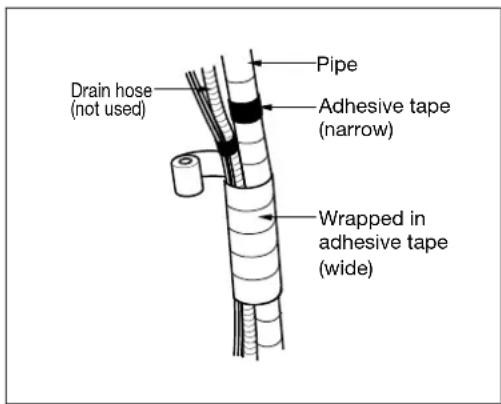
Wrap the pipework in adhesive tape
1) Fix the pipes, mains cable and connection cable with adhesive tape from bottom to top. If they are fixed from top to bottom, rain could enter into the pipes or cables.
2) Fix the bound pipework along the external wall with clamps or similar.
3) A siphon prevents water from entering the electrics.
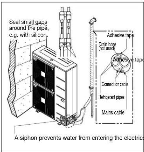
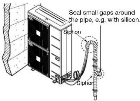
7.4 Leak test and evacuation
Air and moisture in the cooling system have unwanted effects as outlined below.
1) The pressure in the system increases.
2) The operating current increases.
3) The cooling (or heating) output falls.
4) Moisture in the cooling circuit can freeze and block the capillary tubes.
5) Water can cause corrosion on parts in the cooling system.
This means that the indoor and outdoor unit, as well as the connection pipe, must be checked for leaks and pumped empty to remove any non-condensable gases and moisture from the system.
7.4.1 Preparation
Ensure that each pipe (liquid and air side) between the indoor and outdoor unit is connected correctly and the wiring for the test operation has been carried out. Remove the maintenance valve caps from both the gas and liquid side of the outdoor unit. Ensure that both maintenance valves on the liquid and air side of the outdoor unit are closed at this point.
7.4.2 Leak test
■ Connect the multi-way valve (with pressure gauges) and dry nitrogen gas cylinder with the filling hoses on this maintenance connection.
NOTE
A multi-way valve must be used for the leak test. If no multi-way valve is available, an isolating valve can also be used. The "Hi" lever on the 3-way valve must be closed at all times.
The system may be charged with max. 3.0 MPa dry nitrogen. The cylinder valve must be closed with a pressure of 3.0 MPa. The next step is to search for leaks with liquid soap.
NOTE
In order to prevent liquid nitrogen from entering the cooling system, the top side of the gas cylinder must be higher than the bottom side when pressure is building in the system.
1) The gas cylinder is usually used in an upright position. Check all pipe connections (indoor and outdoor) and maintenance valves of the air and liquid side for leaks. Bubbles indicate a leak. The soap must be wiped away with a clean cloth.
2) If no leaks are identified in the system, reduce the nitrogen pressure by removing the filling hose connection from the gas cylinder. When the system pressure is normal again, the hose must be removed from the gas cylinder.
7.4.3 Evacuation
1) Connect the end of the filling hose mentioned above to the vacuum pump to pump the pipework and indoor unit empty. The levers "Lo" and "Hi" on the multi-way valve must be open. Start the vacuum pump. The duration of the pumping empty process varies with different lengths of the pipework and the pump output. The following table shows the time required for pumping empty.
| Time required for pumping empty with a 0.11m_/hour vacuum pump | |
| Length of the pipework less than 10 m | Length of the pipework more than 10 m |
| 30 min. or longer | 60 min. or longer |
| 0.6 mbar or less | |
2) Close the levers "Lo" and "Hi" on the multi-way valve at the desired vacuum pressure and switch off the vacuum pump.
Finally
1) Open the valve handle on the liquid side completely in an anti-clockwise direction with a maintenance valve key.
2) Open the handle of the valve on the gas side completely in an anti-clockwise direction.
3) Loosen the filling hose connected to the air side slightly from the maintenance connection to reduce the pressure, then remove the hose.
4) Tighten the screw nuts and caps on the air side maintenance connection again with an adjustment key. This process is very important to prevent leaks on the system.
5) Position the valve caps on the air and liquid side maintenance valves again and tighten. The purging with the vacuum pump is complete. The split-heat pump is now ready for test operation.
8 Test points, maintenance and troubleshooting
If no faults have occurred here by this point, the unit can now be operated and you can enjoy the benefits of the LWPS split heat pump.
8.1 Checklist prior to commissioning
CAUTION!
Before opening the unit, ensure that all electric circuits are isolated from the power supply.
Before commissioning the unit, run through the test points outlined in this chapter.
You will also find instructions for maintenance and troubleshooting here.
| Pos. | Category | Components | Test point |
| 1 | Current breakers | Field wiring | All switches with contacts with different polarities should be connected securely in accordance with the specified directives or laws.Cable connections should only by made by trained specialist personnel.Cable connections and electrical components available separately should comply with European and local directives.Cable connections should be made in accordance with the circuit diagram provided with this unit. |
| 2 | A circuit breaker (earth leakage breaker) with 30 mA should be installed.The circuit breaker in the control cabinet of the indoor unit should be switched on before the unit is commissioned. | ||
| 3 | E | An earthing wire should be connected. Never connect an earthing wire to a gas pipe, water piping, a metal object of the building, a surge protection socket or similar. | |
| 4 | Power supply unit | Use a separate mains cable. | |
| 5 | Cable connections of the terminal panel | Connections on the terminal panel (in the control cabinet of the indoor unit) should be fixed in place securely enough. | |
| 6 | Water pressure | Filling pressure | After filling with water, the pressure gauge should show a pressure of 1.0 to 1.5 bar. The maximum pressure should not exceed 3.0 bar. |
| 7 | Purging | While filling with water, the system should be purged via the purging hole.If no water comes out after pressing on the tip (on the top side of the opening), the purging process is not yet complete.If the system has been purged optimally, water sprays out like a fountain when pressing on the tip. Take care when testing the purging. Water could spray on your clothes. | |
| 8 | Isolating valve | The isolating valves (on-site) should be open. | |
| 11 | Installing the unit | Maintenance of components | There should be no visibly damaged components in the indoor unit. |
| 12 | Refrigerant leak | Refrigerant leaks reduce the output of the unit. In the event of leaks, please inform an authorised after-sales service partner. |
8.2 Maintenance
To maintain an optimal output on the LWPS split heat pump, regular checks and maintenance work should be carried out on the unit.
It is advisable to work through the following checklist at least once a year.
CAUTION!
Before opening the unit, ensure that all electric circuits are isolated from the power supply.
| Pos. | Category | Components | Test point |
| 1 | Water | Water pressure | In normal operation, the pressure gauge should show a pressure of 2.0 to 2.5 bar.If the pressure is under 0.3 bar, water should be added. |
| 2 | Dirt trap (water filter) | Close the relevant isolating valves and remove the dirt trap. Clean the dirt trapWater may flow out when dismantling the dirt trap. | |
| 4 | C | u Cable connections of the terminal panelr | Check the terminal panel for loose or faulty connections.r en |
8.3 Troubleshooting
If the LWPS split heat pump is experiencing problems during operation or is not working at all, check the following points.
CAUTION!
Before opening the unit, ensure that all electric circuits are isolated from the power supply.
8.3.1 Removing faults during operation
| Pos. Fault Cause Solution | |||
| 1 | Insufficient heating or cooling. | Incorrect setting of the target temperature. | Check the setting of the heating curve on the heat pump manager |
| Insufficient water filling. | Check the pressure gauge and add water until the pressure gauge shows a pressure of 2.0 to 2.5 bar. | ||
| Water flow is low. | Check whether the dirt trap is heavily soiled. If so, the dirt trap must be cleaned.Check whether the pressure indicator shows a pressure of at least 0.3 bar.Check whether the water piping is blocked by soiling or limescale deposits. | ||
| 2 | The outdoor unit is not working, despite correct power supply (information on the control panel). | Temperature on the water inlet is too high. | If there is a temperature above 55 °C on the water inlet, the outdoor unit is switched off to protect the system. |
| Temperature on the water inlet is too low. | If there is a temperature below 5 °C on the water inlet, the outdoor unit is switched off to protect the system. Wait until the temperature on the water inlet has been increased by the indoor unit. | ||
| 3 | Noises from the water pump | Purging has not been completed. | Open the protective cap of the purging and add water until the pressure gauge shows a pressure of 2.0 to 2.5 bar.If no water comes out after pressing on the tip (on the top side of the opening), the purging process is not yet complete. If the system has been purged optimally, water sprays out like a fountain when pressing on the tip. |
| Water pressure is low. | Check whether the pressure indicator shows a pressure of at least 0.3 bar.Check whether the equalising tank and pressure gauge are working correctly. | ||
| 4 | Water is drained off through the drain hose. | Too much water has been added. | Open the lever of the safety valve and drain off more water until the pressure gauge shows a pressure of 2.0 to 2.5 bar. |
| Equalising tank is damaged. | Replace the equalising tank. | ||
| 5 | Domestic water is not heated | Thermal circuit breaker of the flange heater or pipe heater has been triggered | Open the front cover of the indoor component and press the Reset button |
| Domestic water heating was deactivated. | Check the settings on the heat pump manager on the indoor unit. | ||
8.4 Characteristic curve temperature sensor outdoor unit
| NTC - 10 | Air sensor (outdoor unit) | |||||||||||||
| Temperature in °C | -20 | -15 | -10 | -5 | -2 | 0 | 2 | 5 | 10 | 15 | 18 | 20 | 22 | 24 |
| kΩ | 105 | 80.2 | 58.2 | 44.0 | 37.4 | 33.6 | 30.3 | 25.9 | 20.2 | 15.8 | 13.8 | 12.5 | 11.4 | 10.5 |
| Temperature in °C | 25 26 | 28 30 32 | 34 36 3 | 8 40 50 | 60 70 80 | 90 | ||||||||
| kΩ | 10.0 | 9.57 | 8.76 | 8.04 | 7.38 | 6.78 | 6.24 | 5.74 | 5.30 | 3.59 | 2.49 | 1.76 | 1.27 | 0.93 |
| NTC - 5 | Pipe-mounted sensors (outdoor unit) | |||||||||||||
| Temperature in °C | -20 | -15 | -10 | -5 | -2 | 0 | 2 | 5 | 10 | 15 | 18 | 20 | 22 | 24 |
| kΩ | 52.7 | 38.9 | 29.1 | 22.0 | 18.7 | 16.8 | 15.1 | 13.0 | 10.1 | 7.92 | 6.88 | 6.27 | 5.72 | 5.23 |
| Temperature in °C | 25 26 | 28 30 32 | 34 36 3 | 8 40 50 | 60 70 80 | 90 | ||||||||
| kΩ | 5.00 | 4.78 | 4.38 | 4.02 | 3.69 | 3.39 | 3.12 | 2.87 | 2.65 | 1.79 | 1.24 | 0.88 | 0.64 | 0.47 |
| NTC - 200 | Hot gas sensor (output compressor) | |||||||||||||
| Temperature in °C | 1 5 1 | 0 15 20 | 25 30 35 | 40 45 50 | 55 60 65 | |||||||||
| kΩ | 525.00 | 448.00 | 326.00 | 294.33 | 242.20 | 200.00 | 167.57 | 138.03 | 133.80 | 98.00 | 82.00 | 64.50 | 59.00 | 50.71 |
| Temperature in °C | 70 | 75 | 80 | 85 | 90 | 95 | 100 | 105 | 110 | 115 | 120 | 130 | ||
| kΩ | 43.73 | 37.35 | 32.20 | 28.16 | 24.60 | 21.37 | 18.50 | 16.60 | 14.50 | 13.30 | 12.80 | 10.80 | ||
8.5 Characteristic curve temperature sensor indoor unit
8.5.1 Sensor characteristic curves
| Temperature in °C | -20 | -15 | -10 | -5 | 0 | 5 | 10 | ||
| NTC-2 in kΩ | 14.6 | 11.4 | 8.9 | 7.1 | 5.6 | 4.5 | 3.7 | ||
| NTC-10 in kΩ | 67.7 | 53.4 | 42.3 | 33.9 | 27.3 | 22.1 | 18.0 | ||
| 15 | 20 | 25 | 30 | 35 | 40 | 45 | 50 | 55 | 60 |
| 2.9 | 2.4 | 2.0 | 1.7 | 1.4 | 1.1 | 1.0 | 0.8 | 0.7 | 0.6 |
| 14.9 | 12.1 | 10.0 | 8.4 | 7.0 | 5.9 | 5.0 | 4.2 | 3.6 | 3.1 |
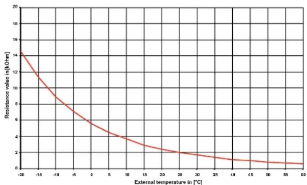
The temperature sensors to be connected to the heat pump manager must correspond to the sensor characteristic curve illustrated in Fig.8.1 on pag. 16. The only exception is the outdoor temperature sensor included in the scope of supply of the heat pump (see Fig.8.2 on pag. 16)
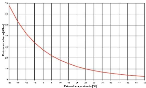
line
| External temperature in [°C] | Resistance value in [kOhm] | | ---------------------------- | -------------------------- | | -26 | 70 | | -15 | 50 | | -10 | 35 | | -5 | 25 | | 0 | 20 | | 5 | 15 | | 10 | 10 | | 15 | 8 | | 20 | 6 | | 25 | 4 | | 30 | 3 | | 35 | 2 | | 40 | 1.5 | | 45 | 1 | | 50 | 0.8 | | 55 | 0.6 | | 60 | 0.4 |Fig. 8.1: Sensor characteristic curve NTC-10
line
| External temperature in [°C] | Resistance value in [kOhm] | | ---------------------------- | -------------------------- | | -20 | 14.0 | | -15 | 12.0 | | -10 | 10.0 | | -5 | 8.0 | | 0 | 6.0 | | 5 | 4.5 | | 10 | 3.5 | | 15 | 3.0 | | 20 | 2.5 | | 25 | 2.0 | | 30 | 1.8 | | 35 | 1.5 | | 40 | 1.2 | | 45 | 1.0 | | 50 | 0.8 | | 55 | 0.6 | | 60 | 0.4 |Fig. 8.2: Sensor characteristic curve NTC-2 according to DIN 44574 Outdoor temperature sensor
8.5.2 Mounting of the external outside temperature sensor (optional)
With outside temperature based control, the connection of an outside temperature sensor (FG 3115) is recommended for mounting on the north side of the building, as incorrect values would otherwise be recorded for the heating curve calculation (e.g. during intensive sun radiation).
The external sensor (FG3115) is connected to the heat pump manager and activated by after-sales service during commissioning.
With room temperature based control via the smart RTC, no additional outside temperature sensor is required.
| Dimensioning parameter sensor lead | |
| Conductor material | Cu |
| Cable-length | 50 m |
| Ambient temperature | 35 °C |
| Laying system | B2 (DIN VDE 0298-4 / IEC 60364-5-52) |
| External diameter | 4-8 mm |
9 Cleaning / maintenance
9.1 Maintenance
To protect the cover, avoid leaning anything against the device or putting objects on the device. External parts can be wiped clean with a damp cloth and domestic cleaner.
CAUTION!
Never use cleaning agents containing sand, soda, acid or chloride, as these can damage the surfaces.
9.2 Cleaning the heating system
The ingress of oxygen into the heating water circuit may result in the formation of oxidation products (rust), particularly if steel components are used. These enter the heating system via the valves, the circulating pumps and/or plastic pipes. A diffusion-resistant installation is therefore essential, especially with regard to the piping of underfloor heating systems.
Residue from lubricants and sealants may also contaminate the heating water.
In the event of severe contamination leading to a reduction in the performance of the liquefier in the heat pump, the system must be cleaned by a heating technician.
Based on current information, we recommend using a 5 % phosphoric acid solution for cleaning purposes. However, if cleaning needs to be performed more frequently, a 5 % formic acid solution should be used.
In both cases, the cleaning fluid should be at room temperature. We recommend flushing the heat exchanger in the direction opposite to the normal flow direction.
To prevent acidic cleaning agents from entering the heating system circuit, we recommend connecting the flushing device directly to the flow and return of the liquefier of the heat pump.
It is then important that the system be thoroughly flushed using appropriate neutralising agents to prevent any damage from being caused by cleaning agent residue remaining in the system.
Acids must be used with care, and the regulations of the employers' liability insurance associations adhered to.
The instructions of the cleaning agent manufacturer must always be observed.
10 Faults / troubleshooting
LAiC devices are high-quality products and should work without problems. Should a fault occur, however, it will be indicated on the heat pump manager display. In this case, consult the "Faults and troubleshooting" page in the operating instructions of the heat pump manager. If you cannot correct the fault yourself, please contact your after-sales service technician.
CAUTION!
Before opening the device, ensure that all circuits are disconnected from the power supply!
After disconnecting the power supply, always wait for at least 5 minutes to allow stored electric charges to dissipate.
CAUTION!
Work on the system must only be performed by authorised and qualified after-sales service technicians!
11 Decommissioning / disposal
Before dismantling the LWPS device, disconnect it from the power source and close all valves. The heat pump must be dismantled by trained personnel. Observe all environmental requirements regarding the recovery, recycling and disposal of materials and components in accordance with all applicable standards.
12 Device information
1. The specified sound levels apply if the supporting feet (available as an option) are not used. If the supporting feet are used, the level can increase by up to 3 dB (A).
| 1 Type and order code | LAK 3IMR | LAK 6IMR | LAK 9IMR | LAK 14IMR | LAK 14ITR | ||
| 2 Design | |||||||
| Heat source Air Air Air Air | |||||||
| 2.1 | Model | Split reversible | Split reversible | Split reversible | Split reversible | Split reversible | |
| 2.2 | Controller | WPM | WPM Econ | WPM Econ | WPM Econ | WPM Econ | |
| 2.3 | Thermal energy metering | no | no | no | no | no | |
| 2.4 | Installation location | Indoors / out-doors | Indoors / out-doors | Indoors / out-doors | Indoors / out-doors | Indoors / out-doors | |
| 2.5 | Performance level | Variable | Variable | Variable | Variable | Variable | |
| 3 Operating limits | |||||||
| 3.1 | Heating water flow / return | °C | up to 55 / from 20 | up to 55 / from 20 | up to 55 / from 20 | up to 55 / from 20 | up to 55 / from 20 |
| 3.2 | Cooling water flow | °C | 7 to 25 | 7 to 25 | 7 to 25 | 7 to 25 | 7 to 25 |
| 3.3 | Air (heating) | °C | -20 to +30 | -20 to +30 | -20 to +30 | -20 to +30 | -20 to +30 |
| 3.4 | Air (cooling) | °C | +10 to +43 | +10 to +43 | +10 to +43 | +10 to +43 | +10 to +43 |
| 4 Flow / sound | |||||||
| 4.1 Heating water flow / internal pressure differential | |||||||
| in accordance with EN 14511 | m^3/h / Pa | 0.530 / 3700 | 1.6 / 20000 | 1.6 / 20000 | 2.4 / 30400 | 2.4 / 30400 | |
| free compression | Pa | 66900 | 38800 | 38800 | 29600 | 29600 | |
| Minimum heating water flow | m^3/h / Pa | 0.3 / 1200 | 0.75 / 8500 | 0.75 / 8500 | 0.9 / 10000 | 0.9 / 10000 | |
| free compression | Pa | 72800 | 68500 | 68500 | 77300 | 77300 | |
| 4.2 Noise-power level in accordance with EN 12102 outdoors^1 | dB(A) | 60 | 63 63 | 68 67 | |||
| 4.3 Sound pressure level in 10 m distance, outdoors ^21 | dB(A) | 30 | 35 35 | 40 39 | |||
| 4.4 Sound power level for outdoor lowered operation ^1 | dB(A) | 51 | 61 | 61 | 65 | 64 | |
| 4.5 Sound pressure level at 10 m distance for outdoor lowered operation ^12 | dB(A) | 21 | 33 | 33 | 37 | 36 | |
| 4.6 Noise-power level in accordance with EN 12102 indoors | dB(A) | 42 | 42 42 | 42 42 | |||
| 4.7 Sound pressure level at a distance of 1 m indoors | dB(A) | 35 | 35 | 35 | 35 | 35 | |
| 4.8 Air flow | m^3/h | 3000 | 3600 | 3600 | 7200 | 7200 | |
| 5 Dimensions, weight and filling quantities | |||||||
| 5.1 Device dimensions^3 x D mm | indoors | H x W | 694x450x240870x655x320 | 694x450x240834x950x330 | 694x450x240834x950x330 | 694x450x2401380x950x330 | 694x450x2401380x950x330 |
| 5.2 Weight of the transport unit(s) incl. packaging indoors / outdoors | kg | 21 / 51 | 23 / 69 | 23 / 69 | 25 / 94 | 25 / 116 | |
| 5.3 Device connections for heating inches | G 1A | G 1A | G 1A | G 1A | G 1A | ||
| 5.4 Refrigerant; total filling weight kg | type/ | R410A / 1.0 | R410A / 1.9 | R410A / 1.9 | R410A / 2.38 | R410A / 2.98 | |
| 5.5 GWP value / CO _2 equivalent | --- / t | 2088 / 2 | 2088 / 4 | 2088 / 4 | 2088 / 5 | 2088 / 6 | |
| 5.6 Lubricant; total filling quantity litres | type/ | Polyvinyl ether (PVE) / 0.57 | Polyvinyl ether (PVE) / 0.9 | Polyvinyl ether (PVE) / 0.9 | Polyvinyl ether (PVE) / 1.3 | Polyvinyl ether (PVE) / 1.3 | |
| 5.7 Volume of heating water in the outdoor component | Litres | 0 | 0 | 0 | 0 | 0 | |
| 5.8 Electrical pipe heater | kW | 2 | 2.4 or 6^4 | 2.4 or 6^4 | 2.4 or 6^4 | 2.4 or 6^4 | |
| 5.9 Start-to-leak pressure, safety valve | bar | 2.5 | 2.5 | 2.5 | 2.5 | 2.5 | |
| 6 Electrical connection | |||||||
| 6.1 Supply voltage / fuse protection Compressor | 1-/N/PE 230 V(50 Hz) / C16 A | 1-/N/PE 230 V(50 Hz) / C25 A | 1-/N/PE 230 V(50 Hz) / C25 A | 1-/N/PE 230 V(50 Hz) / C40 A | 3-/N/PE 400 V(50 Hz) / C16 A | ||
| Electrical pipe heater | 1-/N/PE 230 V(50 Hz) / C10 A | 1-/N/PE 230 V(50 Hz) / C32 A | 1-/N/PE 230 V(50 Hz) / C32 A | 1-/N/PE 230 V(50 Hz) / C32 A | 3-/N/PE 400 V(50 Hz) / C10 A | ||
| Compressor + electrical pipe heater | 3-/N/PE 230 V(50 Hz) / C25 A | 3-/N/PE 400 V(50 Hz) / C25 A | 3-/N/PE 400 V(50 Hz) / C25 A | 3-/N/PE 400 V(50 Hz) / C25 A | |||
| RCD type | B | B | B | B | B | ||
| 6.2 Control voltage / fuse protection | 1-/N/PE 230 V(50 Hz) / C13 A | 1-/N/PE 230 V(50 Hz) / C13 A | 1-/N/PE 230 V(50 Hz) / C13 A | 1-/N/PE 230 V(50 Hz) / C13 A | 1-/N/PE 230 V(50 Hz) / C13 A | ||
| 6.3 Degree of protection according to EN 60 529 indoors/outdoors | IP 20 / IP X4 | IP 20 / IP X4 | IP 20 / IP X4 | IP 20 / IP X4 | IP 20 / IP X4 | ||
| 6.4 Starting current limiter | Inverter | Inverter | Inverter | Inverter | Inverter | ||
| 6.5 Rotary field monitoring | Yes | Yes | Yes | Yes | Yes | ||
| 6.6 Starting current | A | 1.1 | 1.2 | 1.2 | 5,9 | 1.3 | |
| 6.7 Nominal power consumption at A7/W35 / max. consumption 5 6 | kW | 0.65/4.4^7 | 1.17/8.39^7 | 2.11/9.41^7 | 3.31/11,69^7 | 3.39/12.28^7 | |
| 6.8 Nominal current at A7/W35 / cos φ | A/-- | 2.8/0.99 | 5.14/0.99 | 9.27/0.99 | 14,54/0.99 | 4.94/0.99 | |
| 6.9 Nominal power consumption A2 / W35 6 | 0.8 1.41 1.91 3.69 3.50 | ||||||
| 6.10 Power consumption of compressor protection (per compressor) | W | -- | -- | -- | -- | -- | |
| 6.11 Power consumption of fan | W | 43 | 124 | 124 | 248 | 248 | |
| 7 Complies with the European safety regulations | 8 | 8 | 8 | 8 | 8 | ||
| 8 Additional model features | |||||||
| 8.1 Type of defrosting | Reverse circula-tion | Reverse circula-tion | Reverse circula-tion | Reverse circula-tion | Reverse circula-tion | ||
| 8.2 Condensate tray frost protection / Water in device is protected from freezing 9 | No / Yes | No / Yes | No / Yes | Yes/ Yes | Yes/ Yes | ||
| 8.3 Max. operating overpressure (heat source/heat sink) bar | 3.0 | 3.0 | 3.0 | 3.0 | 3.0 | ||
| 9 Heat output / coefficients of performance (COP) | |||||||
| 9.1 Heat output / COP5 | EN 14511 | EN 14511 | EN 14511 | EN 14511 | |||
| at A-15 / W35 | kW / --- 10 | 2.3/2.1 | 3.6/2.3 | 5.2/2.3 | 10.9/2.4 | 10.6/2.4 | |
| kW / --- 6 | 2.3/2.1 | 3.6/2.3 | 5.2/2.3 | 10.9/2.4 | 10.8/2.4 | ||
| at A-7 / W35 | kW / --- 10 | 2.5/2.6 | 4.2/2.8 | 6.3/2.4 | 13.1/2.7 | 13.9/2.9 | |
| kW / --- 6 | 2.5/2.6 | 4.2/2.8 | 6.3/2.4 | 13.1/2.7 | 13.9/2.9 | ||
| at A-7 / W55 | kW / --- 10 | 2.0/1.7 | 2.9/1.8 | 4.2/1.7 | 9.0/1.7 | 11.3/2.1 | |
| kW / --- 6 | 2.0/1.7 | 2.9/1.8 | 4.2/1.7 | 9.0/1.7 | 11.3/2.1 | ||
| at A2 / W35 | kW / --- 10 | 2.6/3.2 | 4.8/3.4 | 5.3/3.6 | 10.7/3.3 | 10.5/3.6 | |
| kW / --- 6 | 2.6/3.2 | 4.8/3.4 | 6.2/3.2 | 12.3/3.3 | 11.0/3.2 | ||
| at A7 / W35 | kW / --- 10 | 3.0/4.6 | 5.6/4.8 | 5.6/4.8 | 10.2/4.4 | 10.6/4.1 | |
| kW / --- 6 | 3.0/4.6 | 5.6/4.8 | 9.0/4.3 | 14.6/4.4 | 14.7/4.3 | ||
| at A7 / W45 | kW / --- 10 | 2.8/3.2 | 5.4/3.4 | 5.4/3.4 | 9.1/3.8 | 9.8/3.7 | |
| kW / --- 6 | 2.8/3.2 | 5.4/3.4 | 8.3/3.3 | 14.0/3.5 | 13.9/3.3 | ||
| at A7 / W55 | kW / --- 10 | 2.5/2.6 | 5.1/2.9 | 5.1/2.9 | 8,7/2.9 | 8.8/2.9 | |
| kW / --- 6 | 2.5/2.6 | 5.1/2.9 | 6.2/2.6 | 12.9/2.9 | 13.2/2.7 | ||
| at A10 / W35 | kW / --- 10 | 3.2/4.8 | 6.0/5.1 | 6,0/5.1 | 10.8/4.6 | 11.3/4.5 | |
| kW / --- 6 | 3.2/4.8 | 6.0/5.1 | 9.6/4.5 | 14.9/4.4 | 15.7/4.3 | ||
| at A20 / W35 | kW / --- 10 | 3.6/4.0 | 7.3/5.8 | 7.3/5.8 | 13.1/5.7 | 13.9/5.5 | |
| kW / --- 6 | 3.6/4.0 | 7.3/5.8 | 10.8/5.3 | 18.8/5.7 | 22.3/5.1 | ||
| at A20/ W55 | kW / --- 10 | 2.2/3.1 | 5.7/3.4 | 5.7/3.4 | 10.6/3.6 | 10.8/3.8 | |
| kW / --- 6 | 2.2/3.1 | 5.7/3.4 | 8.4/3.2 | 16.9/3.7 | 16.2/3.6 | ||
| 9.2 Cooling capacity / COP | |||||||
| at A27 / W7 | kW / --- 6 | 2.4/3.8 | 6.5/3.3 | 6.5/3,3 | 12.4/3.1 | 12.9/3.0 | |
| at A27 / W18 | kW / --- 6 | 3.2/4.6 | 8.7/4.2 | 8.7/4.2 | 16.4/3.8 | 17.1/3.7 | |
| at A35 / W7 | kW / --- 6 | 2.3/3.0 | 6.2/2.6 | 6.2/2.6 | 11.8/2.5 | 12.3/2.5 | |
| at A35 / W18 | kW / --- 6 | 3.0/4.0 | 9.0/3.4 | 9.0/3.4 | 14.0/3.1 | 15.5/3.3 | |
- The specified sound pressure level corresponds to the operating noise of the heat pump in heating operation at 35°C flow temperature.
The specified sound pressure level is the free sound area level. The measured value can deviate by up to 16 dB(A) depending on the installation location. - Please note that additional space is required for pipe connections, operation and maintenance.
- Factory default 6 kW
- These data indicate the size and capacity of the system according to EN 14511. For an analysis of the economic and energy efficiency of the system, the bivalence point and the regulation should be taken into consideration. These figures are only achieved with clean heat exchangers. Instructions for care, commissioning and operation can be found in the relevant sections of the installation and operation instructions. The specified values have the following meaning, e.g. A7 / W35: Heat source temperature 7 °C and heating water flow temperature 35 °C.
- Maximum heating/cooling output
- Max. intake incl. pipe heating and immersion heater (state of supply)
- See CE declaration of conformity
- The heat circulating pump and the heat pump controller must always be ready for operation.
10.COP-optimised operation
13 Product information as per
Regulation (EU) No 813/
2013, Annex II, Table 2
| Information requirements for heat pump space heaters and heat pump combination heaters | ||||||
| Model | LAK 3IMR | |||||
| Air-to-water heat pump | yes | |||||
| Water-to-water heat pump | no | |||||
| Brine-to-water heat pump | no | |||||
| Low-temperature heat pump | yes | |||||
| Equipped with a supplementary heater | yes | |||||
| Heat pump combination heater | no | |||||
| Parameters shall be declared for medium-temperature application, except for low-temperature heat pumps. For low- temperature heat pumps, parameters shall be declared for low-temperature application. | ||||||
| Parameters shall be declared for average climate conditions: | ||||||
| Item Symbol Value Unit Item Symbol Value | Unit | |||||
| Rated heat output (*) | Prated | 2 | kW | Seasonal space heating energy efficiency | ηs | 134 % |
| Declared capacity for heating foer part load at indoor temperature 20°C and outdoor temperature Tj | Declared coefficient of performance or primary energy ratio for part load at indoor temperature 20 °C and outdoor temperature Tj | |||||
| Tj = -7°C | Pdh | 2,5 kW | Tj = -7°C | COPd | 2,60 - | |
| Tj = +2°C | Pdh | 2,6 kW | Tj = +2°C | COPd | 3,35 - | |
| Tj = +7°C | Pdh | 3,1 kW | Tj = +7°C | COPd | 5,28 - | |
| Tj = +12°C | Pdh | 3,6 kW | Tj = +12°C | COPd | 5,25 - | |
| Tj = bivalent temperature | Pdh | 2,4 kW | Tj = bivalent temperature | COPd | 2,39 - | |
| Tj = operation limit temperature | Pdh | 2,4 kW | Tj = operation limit temperature | COPd | 2,39 - | |
| For air-to-water heat pumps | For air-to-water heat pumps: | |||||
| Tj = -15°C (if TOL < -20°C) | Pdh | 2,3 kW | Tj = -15°C (if TOL < -20°C) | COPd | 2,05 - | |
| Bivalent temperature | Tbiv | -10 | °C | For air-to-water heat pumps:Operation limit temperature | TOL | -10 °C |
| Cycling interval capacity for heating | Pcych | - | kW Cycling interval efficiency | COPcyc | - - | |
| Degradation co-efficient (**) | Cdh | 0,90 | - | Heating water operating limit temperature | WTOL | 55 °C |
| Power consumption in modes other than active mode | Supplementary heater | |||||
| Off mode | POFF | 0,015 | kW Rated | heat output (*) | Psup | 0 kW |
| Thermostat-off mode | PTO | 0,020 | kW | Type of energy input | eletrical | |
| Standby mode | PSB | 0,015 | kW | |||
| Crankcase heater mode | PCK | 0,000 | kW | |||
| Other items | ||||||
| Capacity control | variable | For air-to-water heat pumps: Rated air flow rate, outdoors | -3000 | m3/h | ||
| Sound power level, indoors/outdoors | LWA | 42/60 | dB | For water-/brine-to-water heat pumps: Rated brine or water flow rate, outdoor heat exchanger | - | m3/h |
| Emissions of nitrogen oxides | NOx | - | mg/kWh | |||
| For heat pump combination heater: | ||||||
| Declared load profile | - | Water heating energy efficiency | ηwh | - % | ||
| Daily electricity consumption | Qelec | - | kWh | Daily fuel consumption | Qfuel | - kWh |
| Contact details | Glen Dimplex Deutschland GmbH, Am Goldenen Feld 18, 95326 Kulmbach | |||||
| (*) For heat pump space heaters and heat pump combination heaters, the rated output Prated is equal to the design load for heating Pdesignh, and the rated heat output of a supplementary capacity for heating sup(Tj). | ||||||
| (**) If Cdh is not determined by measurement nthen the default degradation is Cdh = 0,9(-) not applicable | ||||||
| Model | LAK 6IMR | |||||
| Air-to-water heat pump | yes | |||||
| Water-to-water heat pump | no | |||||
| Brine-to-water heat pump | no | |||||
| Low-temperature heat pump | yes | |||||
| Equipped with a supplementary heater | yes | |||||
| Heat pump combination heater | no | |||||
| Parameters shall be declared for medium-temperature application, except for low-temperature heat pumps. For low- temperature heat pumps, parameters shall be declared for low-temperature application. | ||||||
| Parameters shall be declared for average climate conditions: | ||||||
| Item Symbol Value Unit Item Symbol Value | Unit | |||||
| Rated heat output (*) | Prated | 4 | kW | Seasonal space heating energy efficiency | ηs | 155 % |
| Declared capacity for heating foer part load at indoor temperature 20°C and outdoor temperature Tj | Declared coefficient of performance or primary energy ratio for part load at indoor temperature 20 °C and outdoor temperature Tj | |||||
| Tj = -7°C | Pdh | 4,2 kW | Tj = -7°C | COPd | 2,83 - | |
| Tj = +2°C | Pdh | 4,8 kW | Tj = +2°C | COPd | 3,67 - | |
| Tj = +7°C | Pdh | 5,7 kW | Tj = +7°C | COPd | 5,66 - | |
| Tj = +12°C | Pdh | 6,4 kW | Tj = +12°C | COPd | 9,72 - | |
| Tj = bivalent temperature | Pdh | 4,0 kW | Tj = bivalent temperature | COPd | 2,62 - | |
| Tj = operation limit temperature | Pdh | 4,0 kW | Tj = operation limit temperature | COPd | 2,62 - | |
| For air-to-water heat pumps | For air-to-water heat pumps: | |||||
| Tj = -15°C (if TOL < -20°C) | Pdh | 3,6 kW | Tj = -15°C (if TOL < -20°C) | COPd | 2,23 - | |
| Bivalent temperature | Tbiv | -10 °C | Operation limit temperature | TOL | -10 °C | |
| Cycling interval capacity for heating | Pcych | - | kW Cycling interval efficiency | COPcyc | - | - |
| Degradation co-efficient (**) | Cdh | 0,90 | - | Heating water operating limit temperature | WTOL | 55 °C |
| Power consumption in modes other than active mode | Supplementary heater | |||||
| Off mode | POFF | 0,015 | kW Rated | heat output (*) | Psup | 0 kW |
| Thermostat-off mode | PTO | 0,020 | kW | Type of energy input | eletrical | |
| Standby mode | PSB | 0,015 | kW | |||
| Crankcase heater mode | PCK | 0,000 | kW | |||
| Other items | For air-to-water heat pumps: Rated air flow rate, outdoors | -3600 | m3/h | |||
| Capacity control | variable | |||||
| Sound power level, indoors/outdoors | LWA | 42/63 | dB | For water-/brine-to-water heat pumps: Rated brine or water flow rate, outdoor heat exchanger | - | m3/h |
| Emissions of nitrogen oxides | NOx | - | mg/kWh | |||
| For heat pump combination heater: | ||||||
| Declared load profile | - | Water heating energy efficiency | ηwh | % | ||
| Daily electricity consumption | Qelec | - | kWh | Daily fuel consumption | Qfuel | kWh |
| Contact details | Glen Dimplex Deutschland GmbH, Am Goldenen Feld 18, 95326 Kulmbach | |||||
| (*) For heat pump space heaters and heat pump combination heaters, the rated output Prated is equal to the design load for heating Pdesignh, and the rated heat output of a supplementary capacity for heating sup(Tj). | ||||||
| (**) If Cdh is not determined by measurement nthen the default degradation is Cdh = 0,9(--) not applicable | ||||||
| Model | LAK 9IMR | |||||
| Air-to-water heat pump | yes | |||||
| Water-to-water heat pump | no | |||||
| Brine-to-water heat pump | no | |||||
| Low-temperature heat pump | no | |||||
| Equipped with a supplementary heater | yes | |||||
| Heat pump combination heater | no | |||||
| Parameters shall be declared for medium-temperature application, except for low-temperature heat pumps. For low- temperature heat pumps, parameters shall be declared for low-temperature application. | ||||||
| Parameters shall be declared for average climate conditions: | ||||||
| Item Symbol Value Unit Item Symbol Value | Unit | |||||
| Rated heat output (*) | Prated | 4 | kW | Seasonal space heating energy efficiency | ηs | 112 % |
| Declared capacity for heating foer part load at indoor temperature 20°C and outdoor temperature Tj | Declared coefficient of performance or primary energy ratio for part load at indoor temperature 20 °C and outdoor temperature Tj | |||||
| Tj = -7°C | Pdh | 4,4 kW | Tj = -7°C | COPd | 1,81 - | |
| Tj = +2°C | Pdh | 5,1 kW | Tj = +2°C | COPd | 2,86 - | |
| Tj = +7°C | Pdh | 5,4 kW | Tj = +7°C | COPd | 3,90 - | |
| Tj = +12°C | Pdh | 5,4 kW | Tj = +12°C | COPd | 5,93 - | |
| Tj = bivalent temperature | Pdh | 4,2 kW | Tj = bivalent temperature | COPd | 1,61 - | |
| Tj = operation limit temperature | Pdh | 4,2 kW | Tj = operation limit temperature | COPd | 1,61 - | |
| For air-to-water heat pumps | For air-to-water heat pumps: TOL < -20°C) | COPd | 1,29 - | |||
| Tj = -15°C (if TOL < -20°C) | Pdh | 3,9 kW | Tj = -15°C (if TOL < -20°C) | For air-to-water heat pumps: Operation limit temperature | TOL | -10 °C |
| Bivalent temperature | Tbiv | -10 °C | ||||
| Cycling interval capacity for heating | Pcych | - | kW Cycling interval efficiency | COPcyc | - | - |
| Degradation co-efficient (**) | Cdh | 0,90 | - | Heating water operating limit temperature | WTOL | 55 °C |
| Power consumption in modes other than active mode | Supplementary heater | |||||
| Off mode | POFF | 0,015 | kW Rated | heat output (*) | Psup | 0 kW |
| Thermostat-off mode | PTO | 0,020 | kW | Type of energy input | eletrical | |
| Standby mode | PSB | 0,015 | kW | |||
| Crankcase heater mode | PCK | 0,000 | kW | |||
| Other items | For air-to-water heat pumps: Rated air flow rate, outdoors | -3600 | m³/h | |||
| Capacity control | variable | |||||
| Sound power level, indoors/outdoors | LWA | 42/63 | dB | For water-/brine-to-water heat pumps: Rated brine or water flow rate, outdoor heat exchanger | - | m³/h |
| Emissions of nitrogen oxides | NOx | - | mg/kWh | |||
| For heat pump combination heater: | ||||||
| Declared load profile | - | Water heating energy efficiency | nwh | % | ||
| Daily electricity consumption | Qelec | - | kWh | Daily fuel consumption | Qfuel | kWh |
| Contact details | Glen Dimplex Deutschland GmbH, Am Goldenen Feld 18, 95326 Kulmbach | |||||
| (*) For heat pump space heaters and heat pump combination heaters, the rated output Prated is equal to the design load for heating Pdesignh, and the rated heat output of a supplementary capacity for heating sup(Tj). | ||||||
| (**) If Cdh is not determined by measurement nthen the default degradation is Cdh = 0,9(-) not applicable | ||||||
| Model | LAK 14IMR | |||||
| Air-to-water heat pump | yes | |||||
| Water-to-water heat pump | no | |||||
| Brine-to-water heat pump | no | |||||
| Low-temperature heat pump | no | |||||
| Equipped with a supplementary heater | yes | |||||
| Heat pump combination heater | no | |||||
| Parameters shall be declared for medium-temperature application, except for low-temperature heat pumps. For low- temperature heat pumps, parameters shall be declared for low-temperature application. | ||||||
| Parameters shall be declared for average climate conditions: | ||||||
| Item Symbol Value Unit Item Symbol Value | Unit | |||||
| Rated heat output (*) | Prated | 11 kW | Seasonal space heating energy efficiency | ηs | 111 % | |
| Declared capacity for heating foer part load at indoor temperature 20°C and outdoor temperature Tj | Declared coefficient of performance or primary energy ratio for part load at indoor temperature 20 °C and outdoor temperature Tj | |||||
| Tj = -7°C | Pdh | 9,6 kW | Tj = -7°C | COPd | 1,83 - | |
| Tj = +2°C | Pdh | 11,9 kW | Tj = +2°C | COPd | 2,77 - | |
| Tj = +7°C | Pdh | 14,2 kW | Tj = +7°C | COPd | 3,86 - | |
| Tj = +12°C | Pdh | 15,8 kW | Tj = +12°C | COPd | 4,55 - | |
| Tj = bivalent temperature | Pdh | 9,6 kW | Tj = bivalent temperature | COPd | 1,83 - | |
| Tj = operation limit temperature | Pdh | 7,9 kW | Tj = operation limit temperature | COPd | 1,46 - | |
| For air-to-water heat pumps | For air-to-water heat pumps: | |||||
| Tj = -15°C (if TOL < -20°C) | Pdh | 4,8 kW | Tj = -15°C (if TOL < -20°C) | COPd | 0,84 - | |
| Bivalent temperature | Tbiv | -10 °C | For air-to-water heat pumps:Operation limit temperature | TOL | -10 °C | |
| Cycling interval capacity for heating | Pcych | - | kW Cycling interval efficiency | COPcyc | - | |
| Degradation co-efficient (**) | Cdh | 0,99 | - | Heating water operating limit temperature | WTOL | 55 °C |
| Power consumption in modes other than active mode | Supplementary heater | |||||
| Off mode | POFF | 0,015 | kW Rated | heat output (*) | Psup | 3 kW |
| Thermostat-off mode | PTO | 0,020 | kW | Type of energy input | eletrical | |
| Standby mode | PSB | 0,015 | kW | |||
| Crankcase heater mode | PCK | 0,000 | kW | |||
| Other items | ||||||
| Capacity control | variable | For air-to-water heat pumps: Rated air flow rate, outdoors | -7200 | |||
| Sound power level, indoors/outdoors | LWA | 42/68 | dB | For water-/brine-to-water heat pumps: Rated brine or water flow rate, outdoor heat exchanger | - | -- m3/h |
| Emissions of nitrogen oxides | NOx | - | mg/kWh | |||
| For heat pump combination heater: | ||||||
| Declared load profile | - | Water heating energy efficiency | ηwh | - % | ||
| Daily electricity consumption | Qelec | - | kWh | Daily fuel consumption | Qfuel | - kWh |
| Contact details | Glen Dimplex Deutschland GmbH, Am Goldenen Feld 18, 95326 Kulmbach | |||||
| (*) For heat pump space heaters and heat pump combination heaters, the rated output Prated is equal to the design load for heating Pdesignh, and the rated heat output of a supplementary capacity for heating sup(Tj). | ||||||
| (**) If Cdh is not determined by measurement nthen the default degradation is Cdh = 0,9(-) not applicable | ||||||
| Model | LAK 14ITR | |||||
| Air-to-water heat pump | yes | |||||
| Water-to-water heat pump | no | |||||
| Brine-to-water heat pump | no | |||||
| Low-temperature heat pump | no | |||||
| Equipped with a supplementary heater | yes | |||||
| Heat pump combination heater | no | |||||
| Parameters shall be declared for medium-temperature application, except for low-temperature heat pumps. For low- temperature heat pumps, parameters shall be declared for low-temperature application. | ||||||
| Parameters shall be declared for average climate conditions: | ||||||
| Item Symbol Value Unit Item Symbol Value | Unit | |||||
| Rated heat output (*) | Prated | 10 kW | Seasonal space heating energy efficiency | ηs | 116 % | |
| Declared capacity for heating foer part load at indoor temperature 20°C and outdoor temperature Tj | Declared coefficient of performance or primary energy ratio for part load at indoor temperature 20 °C and outdoor temperature Tj | |||||
| Tj = -7°C | Pdh | 11,4 kW | Tj = -7°C | COPd | 2,08 - | |
| Tj = +2°C | Pdh | 9,7 kW | Tj = +2°C | COPd | 2,95 - | |
| Tj = +7°C | Pdh | 10,0 kW | Tj = +7°C | COPd | 3,65 - | |
| Tj = +12°C | Pdh | 9,9 kW | Tj = +12°C | COPd | 4,47 - | |
| Tj = bivalent temperature | Pdh | 9,8 kW | Tj = bivalent temperature | COPd | 1,83 - | |
| Tj = operation limit temperature | Pdh | 9,8 kW | Tj = operation limit temperature | COPd | 1,83 - | |
| For air-to-water heat pumps | For air-to-water heat pumps: | |||||
| Tj = -15°C (if TOL < -20°C) | Pdh | 6,3 kW | Tj = -15°C (if TOL < -20°C) | COPd | 1,21 - | |
| Bivalent temperature | Tblv | -10 °C | For air-to-water heat pumps: Operation limit temperature | TOL | -10 °C | |
| Cycling interval capacity for heating | Pcych | - | kW Cycling interval efficiency | COPcyc | - | - |
| Degradation co-efficient (**) | Cdh | 0,99 | - | Heating water operating limit temperature | WTOL | 55 °C |
| Power consumption in modes other than active mode | Supplementary heater | |||||
| Off mode | POFF | 0,015 | kW Rated | Psup | 3 | kW |
| Thermostat-off mode | PTO | 0,020 | kW | Type of energy input | eletrical | |
| Standby mode | PSB | 0,015 | kW | |||
| Crankcase heater mode | PCK | 0,000 | kW | |||
| Other items | For air-to-water heat pumps: Rated air flow rate, outdoors | -7200 | m3/h | |||
| Capacity control | variable | |||||
| Sound power level, indoors/outdoors | LWA | 42/67 | dB | For water-/brine-to-water heat pumps: Rated brine or water flow rate, outdoor heat exchanger | - | m3/h |
| Emissions of nitrogen oxides | NOx | - | mg/kWh | |||
| For heat pump combination heater: | ||||||
| Declared load profile | - | Water heating energy efficiency | nwh | % | ||
| Daily electricity consumption | Qelec | - | kWh | Daily fuel consumption | Qfuel | kWh |
| Contact details | Glen Dimplex Deutschland GmbH, Am Goldenen Feld 18, 95326 Kulmbach | |||||
| (*) For heat pump space heaters and heat pump combination heaters, the rated output Prated is equal to the design load for heating Pdesignh, and the rated heat output of a supplementary capacity for heating sup(Tj). | ||||||
| (**) If Cdh is not determined by measurement nthen the default degradation is Cdh = 0,9 (-) not applicable | ||||||
Table des matières
natural_image
Front view of a white appliance casing with internal components and a central display (no text or symbols visible)e s ATTENTION!
flowchart
graph TD
    A["Brise marine"] --> B["Top structure: brick building with circular inset image"]
    B --> C["Down arrow"]
    C --> D["Bottom structure: brick building with circular inset image"]
REMARQUE
Pour LAK3IMR, LAK6IMR, LAK9IMR, LAK14IM
| Nr. | Name |
| 1 | Exhaust air grid |
| 2 | Cable entry cover |
| 3 | Cabel feedthrough |
| 4 | Refrigerant connection cover |
| 5 | Maintenance interval gas side |
| 6 | Maintenance interval liquid side |
Outdoor unit (external)
Heat output of the device:
To the rain water channel or the bottom frost line /
Connection for split line ∅ 6 (flare connection)
Connection for split line ∅ 12 (flare connection)
Hose connection safety valve (on site)
Electrical cable entry
Flow G1A
Return G1A
connection condensate hos (on site)
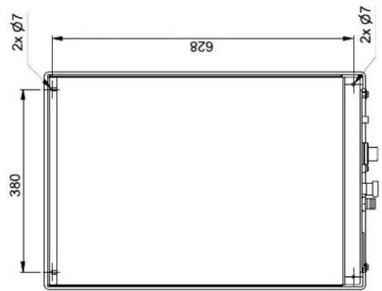
Raccordement de la conduite des deux unités ∅10 (raccord à visser)
Raccordement de la conduite des deux unités ∅16 (raccord à visser)
Raccordement flexible de la soupape de sécurité (sur place)
Passage de câble électrique
Départ circuit de chauffage G1A
Retour circuit de chauffage G1A
Raccordement du flexible de condensats (sur place)
Connection for split line ∅ 10 (flare connection)
Connection for split line ∅ 16 (flare connection)
Hose connection safety valve (on site)
Electrical cable entry
Flow G1A
Return G1A
connection condensate hos (on site)
1 Anschluss Splitleitung ∅ 10 (Bördelausschluss)
2 Anschluss Splitleitung ∅ 16 (Bördelanschluss)
3 Schlauchanschluss Sicherheitsventil (bauseits)
4 Elektrische Leitungseinführung
5 Heizungsvorlauf G1A
6 Heizungsrücklauf G1A
7 Anschluss Kondensatschlauch (bauseits)
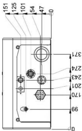
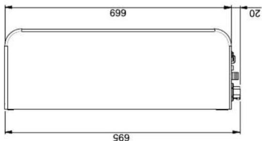
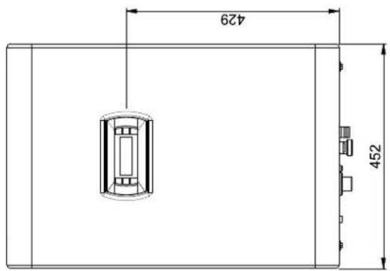
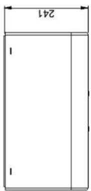
2 Diagramme / Diagrams / Diagrammes
You can find and download the current CE conformity declaration at:
F-67590 Schweighouse Sur Moder
T+33 3 88 07 18 00
F +33 3 88 07 18 01
dimplex-ST@dimplex.de
www.dimplex.de/fr
Verkauf und Planung
Projektierung
- LAK 3IMR LAK 6IMR LAK 9IMR LAK 14IMR LAK 14ITR
- Installation and Operating Instruction
- ! ACHTUNG!
- Purpose......EN-3
- Scope of supply......EN-3
- Outdoor unit....EN-4
- Assembly indoor unit......EN-6
- Commissioning......EN-8
- Connecting the pipework and cables to the outdoor unit......EN-9
- Test points, maintenance and troubleshooting......EN-14
- Cleaning / maintenance ...... EN-17
- Faults / troubleshooting....EN-17
- Decommissioning / disposal......EN-17
- Device information ...... EN-18
- Product information as per Regulation (EU) No 813/2013, Annex II, Table 2......EN-20
- Anhang · Appendix · Annexes ...... A-I
- Safety not 1.3 Intended use
- Symbols and markings
- CAUTION!
- NOTE
- Important notes
- Legal regulations and guidelines
- Pur p o s e
- Area of application
- General properties
- Scope of supply
- Indoor unit
- Hydraulic components
- Safety equipment:
- Refrigerating equipment
- Contact plate
- Wärmepumpenmanager
- Outdoor unit
- Installation
- Wall opening for split lines and electric wires
- Wall opening for condensate drain
- Installation in coastal areas
- Precautions in winter and in seasonal winds
- Assembly indoor unit
- General
- Indoor unit fixing
- Heating system connection
- Minimum heating water flow rate
- Frost protection
- Commissioning
- General
- Preparation
- Commissioning procedure
- Connecting the pipework and cables to the outdoor unit
- Refrigerant pipes
- Requirements for pipe length and rise
- Preparation for pipework
- Step 1: Cutting pipes and cables
- Step 2: Removing burrs
- Step 3: Inserting screw nuts
- Step 4: Flanging
- Step 5: Checks
- Pipe connections on the indoor unit
- Step 1: Initial fastening
- Step 2: Fastening
- Pipe connections on the outdoor unit
- Step 1: Determining the direction in which the pipes are to run
- Step 3: Preventing foreign bodies from entering the unit
- Electrical connections
- Outdoor unit
- For LAK 3IMR, LAK 6IMR, LAK 9IMR, LAK 14IMR:
- For LAK 14ITR
- Indoor unit
- For LAK 3IMR, LAK 6IMR, LAK 9IMR
- For LAK 14IMR
- Final work
- Pipe bends
- Wrap the pipework in adhesive tape
- Leak test and evacuation
- Preparation
- Leak test
- Evacuation
- Finally
- Test points, maintenance and troubleshooting
- Checklist prior to commissioning
- Maintenance
- Troubleshooting
- Removing faults during operation
- Characteristic curve temperature sensor outdoor unit
- Characteristic curve temperature sensor indoor unit
- Sensor characteristic curves
- Mounting of the external outside temperature sensor (optional)
- Cleaning / maintenance
- Maintenance
- Cleaning the heating system
- Faults / troubleshooting
- Decommissioning / disposal
- Product information as per
- Regulation (EU) No 813/
- 2013, Annex II, Table 2
- Table des matières
- e s ATTENTION!
- REMARQUE
- Pour LAK3IMR, LAK6IMR, LAK9IMR, LAK14IM
- Diagramme / Diagrams / Diagrammes
- Verkauf und Planung
- Projektierung
Brand : DIMPLEX
Model : LAK 9IMR
Category : Heat pump