
TR93 - Thermostat Renkforce - Free user manual and instructions
Find the device manual for free TR93 Renkforce in PDF.
| Brand | Renkforce |
| Model | TR93 (TR-93) |
| Product type | Mechanical room thermostat |
| Operating voltage | 220-250 V/AC, 50/60 Hz |
| Protection class | II |
| Switching capacity (resistive load) | Max. 16 A |
| Temperature setting range | +5 °C to +30 °C |
| Switching temperature difference | < 1 °C |
| Ambient conditions | Temperature: 0 °C to +45 °C, relative humidity: 25% to 90% (non-condensing) |
| Main function | Automatic temperature control for heating or cooling |
| Frost protection | Yes, setting at +5 °C (snowflake symbol) |
| Connection type | Screw terminals (3 terminals) |
| Mounting | Wall-mounted, on flush-mounted box (60 mm spacing) or directly on wall |
| Recommended mounting height | Approximately 1.5 m |
| Material | Plastic |
| Maintenance and cleaning | Dry, soft cloth or vacuum cleaner; do not use aggressive products |
| Safety | Installation by a qualified electrician; disconnect power before any intervention |
| Spare parts and repairability | No user-serviceable parts; maintenance by a specialist only |
| General information | Use in dry, closed indoor areas; do not expose to moisture |
| On/Off switch | Sliding ON/OFF switch on top |
| Integrated control light | Yes, lights up with the load (depending on wiring) |
Frequently Asked Questions - TR93 Renkforce
User questions about TR93 Renkforce
0 question about this device. Answer the ones you know or ask your own.
Ask a new question about this device
Download the instructions for your Thermostat in PDF format for free! Find your manual TR93 - Renkforce and take your electronic device back in hand. On this page are published all the documents necessary for the use of your device. TR93 by Renkforce.
USER MANUAL TR93 Renkforce
The product is used to automatically turn on/off an electric load (e.g. heater or air conditioner) when the temperature is below/above a certain level.
See chapter "Technical data" for information on connection and the maximum permissible power consumption of the connected electrical loads.
The product may only be used in dry, enclosed spaces.
Always observe the safety instructions and all other information included in these operating instructions. Read the operating manual carefully; keep it in a safe place or pass it on to others using the product.
Any use other than that described above could lead to damage to this product and involves the risk of short circuits, fire, electric shock, etc. No part of the product may be modified or converted!
This product complies with the applicable national and European requirements. All names of companies and products are the trademarks of the respective owners. All rights reserved.
Package contents
- Room temperature controller
- Installation material (4x screws, 4x wall screw-plugs)
- Operating instructions
Explanation of symbols, labels

The lightning symbol inside a triangle is used when there is a potential risk of personal injury, such as electric shock.

This symbol points to specific risks associated with handling, function or operation.

The "arrow" symbol points to special tips and operating information.

The product is designed according to Protection Class II.

Observe the operating instructions!
Safety instructions
Damage due to not following these operating instructions will void the warranty! We do not assume any liability for any resulting damage! We do not assume any liability for material and personal damage caused by improper use or non-compliance with the safety instructions! In such cases, the warranty will be null and void!
Attention, important note!
This device should be installed only by people with relevant electro-technical knowledge and experience!*)
If it is installed improperly, you risk:
- Your own life
The life of the user of the electrical system.
If it is installed improperly, you risk severe damage to property, e.g., by fire. You face the risk of personal liability for personal injury and material damage.
Contact an electrician!
\* specialist knowledge required for the installation:
For the installation, especially the following specialist knowledge is required: "5 safety rules" to be followed: Switch off power; secure against switching back on; determine voltage-free status; earthing and short-circuiting; cover or fence off nearby live parts
- selection of the suitable tool, the meter and if necessary the personal protective equipment
- evaluation of the measurement results
- selection of the electrical installation material to ensure the disconnect conditions
IP protection types - installation of the electrical installation material
- type of mains supply network (TN system, IT system, TT system) and the connection conditions that follow from them (classical earthing, protective earthing, required additional measures, etc.)
If you do not have the expertise required for connection and installation, do not connect and install it yourself but ask a qualified technician.
a) General
The unauthorised conversion and/or modification of the product is not permitted for safety and approval reasons (CE). Never open/dismantle it (apart from the works for installation and connection described in the manual)! It does not contain any internal parts that need to be adjusted or maintained by you.
Maintenance, adjustment or repair work may only be carried out by an expert/authorised service centre, which is familiar with the hazards involved and the relevant regulations.
The product is not a toy and does not belong in the hands of children. There is a risk of a life-threatening electric shock!
- In commercial institutions, the accident prevention regulations of the Employer's Liability Insurance Association for Electrical Systems and Operating Facilities are to be observed!
- Do not carelessly leave the packaging material lying around, since this may become a dangerous plaything for children.
- Handle the product with care; it can be damaged by impacts, blows, or accidental falls, even from a low height.
If you have any questions that are not answered in these operating instructions, please contact our technical department or another specialist.
b) Operating location
The product may be used in dry, enclosed indoor areas only; it must not get damp or wet!
- Only install and use the product when it is firmly mounted.
- Nevertheless, take special caution when children are around. Children cannot recognise the danger arising from the incorrect use of electrical devices. There is a risk of a life-threatening electric shock!
The product must not be exposed to extreme temperatures, direct sunlight, strong vibrations, dust, dirt or heavy mechanical stress. Keep the product away from strong magnetic fields generated by machines, electric motors or loudspeakers.
- Do not operate the device in environments where there are high levels of dust, flammable gases, vapours or solvents. There is a danger of fire and explosion!
c) Installation, connection
The product is constructed according to Protection Class II.
- During installation, all poles must be disconnected from the mains voltage, e.g., via RCD. Between the RCD and the product, there must be an appropriately dimensioned fuse or circuit breaker (max. 16 A).
- Install the product only in an easy-to-reach position.
- Perform installation and connection only when all supply lines are disconnected from the mains voltage. Otherwise, there is a risk of a life-threatening electric shock!
- Also observe the safety and operating instructions of any other devices that are connected to this product.
not connect the product to the power supply immediately after it has been transferred from a cold room into a warm one (e.g., during transport). The condensation that forms might destroy the device. Moreover, there is danger of electric shock!
the device to reach room temperature before switching it on. Wait until the condensation has evaporated. This might take several hours. Only after this should it be installed, connected to the mains supply and put into use.
d) Handling, operation
- Never overload the product. Observe the maximum connected load specified in the chapter "Technical data".
- This product should never be touched or operated with wet hands. There is a risk of a life-threatening electric shock!
- Never pour any liquids above or next to the product. You run the risk of causing a fire or a fatal electric shock!
If any liquid has still managed to enter the device, immediately turn off the mains supply at all poles (turn off the automatic circuit breaker or remove the fuse, then switch of the residual current operated circuit breaker of the associated circuits). Contact a specialist. Do not use the product any longer.
- Use the product only in a temperate climate, never in a tropical climate.
- Do not use the product if it is damaged. There is a risk of a life-threatening electric shock!
- If it can be assumed that safe operation is no longer possible, the product must be turned off and precautions must be taken to ensure that it is not used unintentionally. Do not touch the product or any device connected to it.
First switch off the mains voltage to all poles (switch off the connected circuit breaker or remove the fuse and then switch off the connected RCD).
- Safe operation can no longer be assumed if:
- the product shows visible signs of damage
- the product does not work at all or works poorly (leaking smoke or a smell of burning, audible cracking noises, discolouration to the product or the adjacent surfaces)
- the product was stored under unfavourable conditions
- it was exposed to heavy loads during transport
Preparations for connection and installation
- The device must be voltage-free during installation and connection.
Switch off all the poles of the mains cable by removing the corresponding fuse or switching off at the circuit breaker. Then, also switch off the associated ground fault circuit interrupter (breaker). Secure it against unauthorised reconnection, e.g., with a danger sign.
- Check that the mains leads are without current, e.g., by means of an appropriate tester.
- Select an appropriate installation location.
To ensure the room temperature controller functions without fault, it must be installed so it is not close to heaters, windows, doors, air discharge openings, etc. Also keep the room temperature controller out of drafts.
Do not mount the room temperature controller behind furniture or curtains.
Because the exterior walls of a building are generally colder than the walls in the interior of the building (depending on the building insulation), the room temperature controller should not be mounted there.
Wall heaters work with air convection. Thus, warm air rises from the heater, cools slowly and sinks back down on the other side of the room. Therefore, an ideal location for installing the room temperature controller is on the wall opposite a heater; see figure.
The ideal installation height is approx. 1.5m
Installation and connection

Pay attention to the chapter "Safety instructions" and the chapter "Preparations for connection and installation".
- First, switch off the mains voltage to all poles.
- Pull off the control knob of the room temperature controller; it is only loosely attached.
-
Remove the two cross-head screws and remove the cover.
-
The bottom plate with the room temperature controller can be installed directly on an in-wall power socket via the fastening holes using screws (distance between holes/screws 60~mm ).
Fasten the room temperature sensor in such a way that the on/off switch is located at the bottom right.
Depending on the wall surface, the room temperature controller can also be secured to the wall with appropriate screws and wall plugs.

Make certain when drilling and tightening the screws that no cables or pipes are damaged!
Before installation, run the power cable and the connection cables to the load to be connected through the opening next to the screw terminals.
- Now connect the mains cable and the connection cable with the load. The number of the contact allocation can be found next to the screw terminal.

The following circuit shows the connection of a heater.
During later operation and when the room temperature controller is switched on (sliding switch in position "ON"), the heater ("LOAD") is activated when the temperature falls below the set value.
The heater is switched off again when the desired temperature is reached.
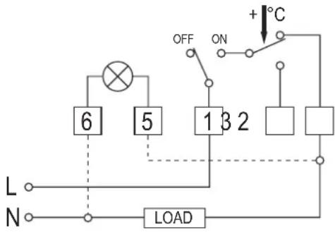
The dashed lines indicate the connection of the integrated control light. In the circuit diagram shown above, the control light is activated when the electric load is switched on.

If an air conditioner is to be controlled with the room temperature controller, it must be connected to terminal 3 (instead of terminal 2).
During later operation and when the room temperature controller is switched on (sliding switch in position "ON"), the air conditioning ("LOAD") is activated when the temperature exceeds the set value.
The air conditioning is switched off again when the desired temperature is reached.
To avoid too frequent or quick successive switching processes, the air conditioning should have a protection circuit.
- Replace the cover correctly and secure it with the two fastening screws.
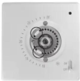
- The rotating range of the control knob can be limited.
To do this, you can move the two small white plastic pins (see circle on the right of the figure) located in the holes around the rotational axis to a different location.
- Put on the control knob again.

Always pay attention to the correct position; the control knob can only be attached to the rotational axis in one orientation.
If you have limited the rotation range with the plastic pins, it may be necessary to rotate the rotational axis a little further by hand so that the control knob can be attached.
Do no use force when attaching the control knob!
Operation
- The room temperature controller can be switched on with the sliding switch (switch position "ON" = on, switch position "OFF" = off).
The room temperature controller can only function (and control the connected load), when it is switched on. - Use the control knob to set the desired temperature. The position with the snowflake symbol indicates the frost-protection temperature (+5^) , e.g., for a storage room.
- Depending on the temperature settings, the connected load is switched on or off.
Troubleshooting
The temperature set in the room temperature controller deviates from the actual room temperature (e.g., as measured with a thermometer)
- The heating power of your room radiator is insufficient (or the cooling power of your air conditioning is too low).
- The room temperature controller is influenced by external heat (e.g., by sunlight, proximity to heaters or electrical devices).
- The room temperature controller is installed next to a door or window where draught affects the room temperature.
- The room temperature controller is installed in a disadvantageous position, e.g., behind a curtain or on an exterior building wall.
The room temperature is not the same everywhere in the room.
Depending on the existing heating system (e.g., underfloor heating), air circulation, installation height and the wall temperature, considerable variations between the set position on the room temperature controller and the temperature measured with a thermometer.
Slow response of the room temperature to the temperature set on the room temperature controller
- In well-insulated buildings, it can take a long time for the room temperature to fall. On the other hand, it can take a long time for the temperature to rise in poorly insulated buildings and with cold exterior walls.
- Underfloor heating also reacts very slowly to the temperature setting on the room temperature controller.
Maintenance and cleaning
The product is maintenance-free. Repair or maintenance work must be carried out by a specialist.
You can use a clean, dry, soft cloth for cleaning. Dust can be removed very easily with a vacuum cleaner.
Do not use aggressive chemical or scouring cleaning agents, as this may lead to discoloration or changes in the material on the surface.
Disposal

The product must not be disposed of in the household waste!
We dispose of the product, when it is no longer of use, according to the
current statutory requirements.
Technical data
Operating voltage. 220 - 250 V/AC, 50/60 Hz
Protection class..
Contact rating. Resistive load: max. 16 A
Inductive load: max 4 A
Devices with mainly resistive load are, e.g., light bulbs.
Loads with inductive load are, e.g., engines, control gears, conventional transformers.
Ambient conditions. Temperature 0^ to +45^ , air humidity 25% to
90% relative, non-condensing
Control/set range +5^ to +30^
Switching temperature difference < 1°C
Dimensions. 80 x 80 x 37 mm (W x H x D)
Weight 122g
Mode d'emploi
c) Montage, raccordement
Charge inductive:Max.4A

Dimensions. 80 x 80 x 37 mm (I x H x P)
Poids. 122g
Gebruiksaanwijzig
Kamerthermostat „TR-93"
Bestelnr. 1323079
Beoogd gebruik


- Package contents
- Explanation of symbols, labels
- Safety instructions
- Attention, important note!
- \* specialist knowledge required for the installation:
- If you do not have the expertise required for connection and installation, do not connect and install it yourself but ask a qualified technician.
- a) General
- b) Operating location
- c) Installation, connection
- d) Handling, operation
- Preparations for connection and installation
- Installation and connection
- Operation
- Troubleshooting
- Maintenance and cleaning
- Disposal
- Technical data
- Mode d'emploi
- c) Montage, raccordement
- Gebruiksaanwijzig
- Kamerthermostat „TR-93"
- Beoogd gebruik
Brand : Renkforce
Model : TR93
Category : Thermostat