OptiPlex SX270 - Desktop computer DELL - Free user manual and instructions
Find the device manual for free OptiPlex SX270 DELL in PDF.


| Product type | Desktop computer |
| Brand | Dell |
| Model | OptiPlex SX270 |
| Processor | Intel Pentium 4 (up to 2.8 GHz) |
| Memory | Up to 2 GB DDR SDRAM |
| Storage | IDE hard drive (up to 80 GB) |
| Dimensions (H × W × D) | Approximately 9.1 × 27.9 × 35.6 cm |
| Weight | Approximately 5.4 kg |
| Power supply | 200 W (internal power supply) |
| Main functions | Office work, internet browsing, basic multimedia; USB, serial, parallel, VGA, Ethernet, audio ports |
| Maintenance and cleaning | Clean with a soft, dry cloth; avoid liquids; dust vents regularly |
| Security | Chassis intrusion detection; optional hood lock |
| Spare parts and repairability | System board, heat sink, fan, hard drive, modular peripheral |
| General information | Launch year: 2003; operating system: Windows XP |
Frequently Asked Questions - OptiPlex SX270 DELL
User questions about OptiPlex SX270 DELL
0 question about this device. Answer the ones you know or ask your own.
Ask a new question about this device
Download the instructions for your Desktop computer in PDF format for free! Find your manual OptiPlex SX270 - DELL and take your electronic device back in hand. On this page are published all the documents necessary for the use of your device. OptiPlex SX270 by DELL.
USER MANUAL OptiPlex SX270 DELL
Replacing the System Board
0Y0561.book Page 2 Thursday, May 8, 2003 9:45 AM

0Y0561.book Page 1 Thursday, May 8, 2003 9:45 AM
Dell™ Computers
Replacing the System Board

DELL™
www.dell.com | support.dell.com


Notes, Notices, and Cautions
NOTE: A NOTE indicates important information that helps you make better use of your computer.
NOTICE: A NOTICE indicates either potential damage to hardware or loss of data and tells you how to avoid the problem.
CAUTION: A CAUTION indicates a potential for property damage, personal injury, or death.

CAUTION: Before you begin this procedure, follow the safety instructions in the Setup and Quick Reference Guide.

CAUTION: To prevent static damage to components inside your computer, discharge static electricity from your body before you touch any of your computer's electronic components. You can do so by touching an unpainted metal surface on the computer chassis.
1 Shut down the computer through the Start menu.
2 Ensure that your computer and attached devices are turned off. If your computer and attached devices did not automatically turn off when you shut down your computer, turn them off now.
NOTICE: To disconnect a network cable, first unplug the cable from your computer and then unplug it from the network wall jack.
3 Disconnect any telephone or telecommunication lines from the computer.
4 Disconnect your computer and attached devices from their electrical outlets, and then press the power button to ground the system board.
5 Remove the computer from the mounting plate (if used).
6 Remove the cable cover, if it is attached.
7 Remove the stand, if it is attached.


CAUTION: To guard against electrical shock, always unplug your computer from the electrical outlet before removing the cover.

NOTICE: Before touching anything inside your computer, ground yourself by touching an unpainted metal surface, such as the metal at the back of the computer. While you work, periodically touch an unpainted metal surface to dissipate any static electricity that could harm internal components.
8 Remove the following components in the order in which they are listed (for detailed removal steps, see the User's Guide):
a Module device
b Hard drive
c Computer cover





0Y0561.book Page 4 Thursday, May 8, 2003 9:45 AM

www.deell.com | support.deell.com
d Heat-sink fan shroud
e Heat sink
f Chassis intrusion switch
9 Remove the heat-sink retention base by removing the four green screws that secure the retention base to the chassis.
10 Remove the five silver screws that secure the system board to the chassis.
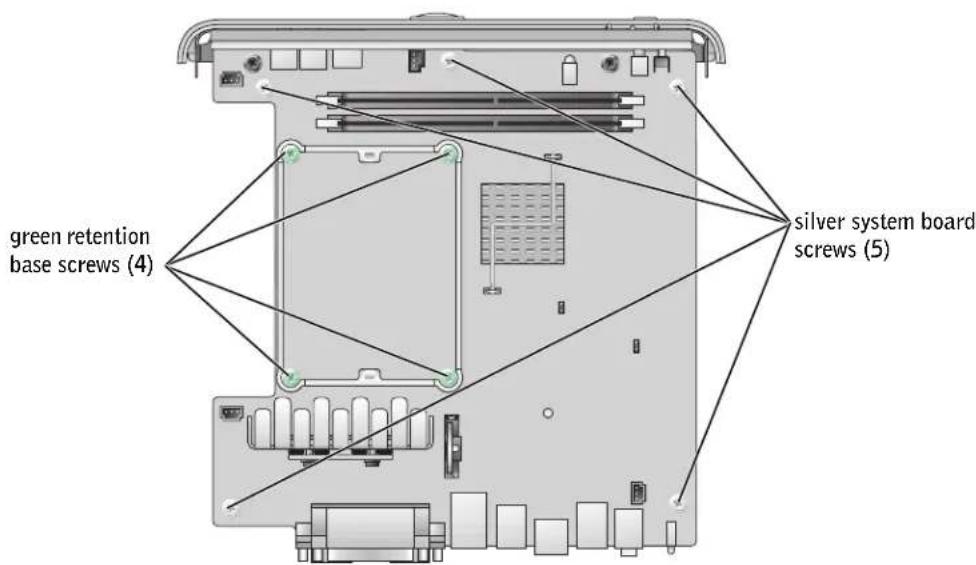

NOTICE: The module device connector is attached underneath the system board. When removing the system board, be careful not to bump or catch the connector on the metal chassis floor.
4 Replacing the System Board





0Y0561.book Page 5 Thursday, May 8, 2003 9:45 AM

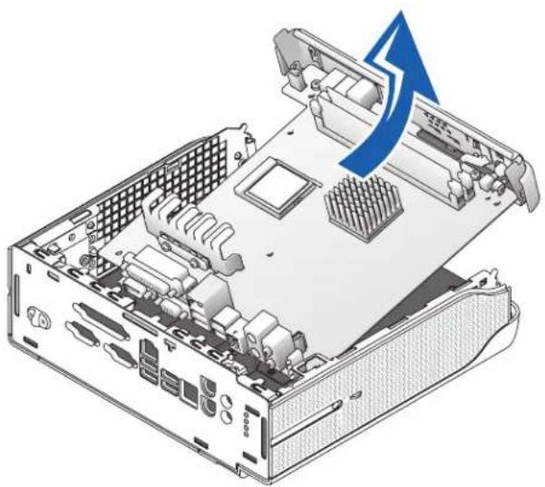
11 Remove the system board and I/O shield assembly by slightly sliding the board toward the front of the computer and lifting up.
natural_image
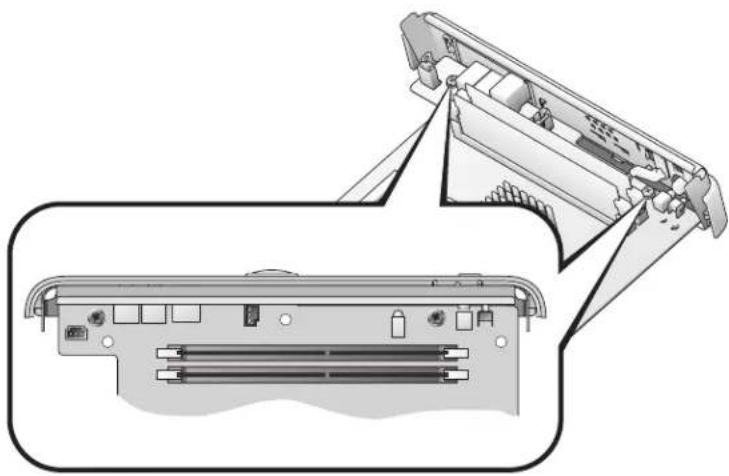
Illustration of an open computer drive chassis showing internal components and a blue arrow indicating a process or operation (no text or symbols present)12 Remove the two black screws that secure the I/O shield to the system board.
natural_image
Technical diagram of a device showing internal components and external structure (no text or symbols)Replacing the System Board 5







0Y0561.book Page 6 Thursday, May 8, 2003 9:45 AM


www.dell.com | support.dell.com
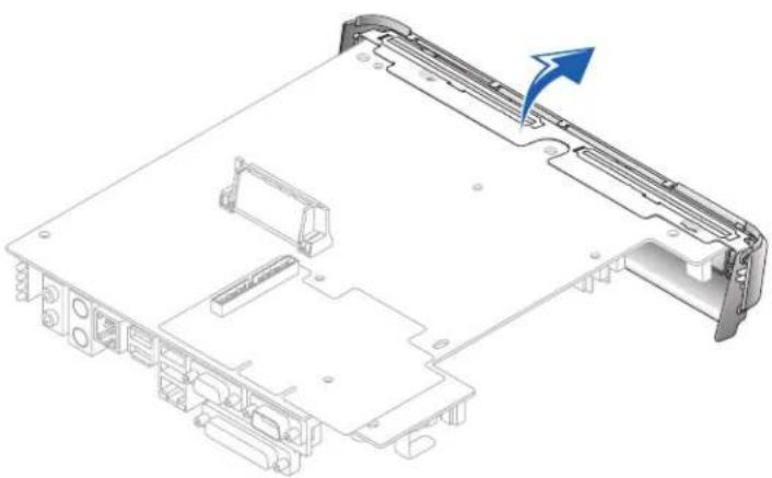
13 Remove the I/O shield:
a Turn the system board upside down.
b Carefully insert a blunt, nonconducting object such as a plastic screwdriver under the I/O shield and pry the shield away from the system board until the shield dislodges from the system board.
natural_image
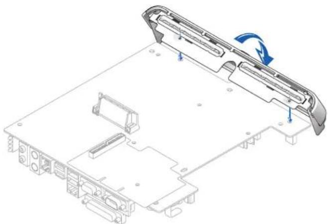
Technical line drawing of a computer chassis with an arrow indicating a component (no text or symbols present)14 Attach the I/O shield to the replacement system board:
a Align the two flanged screw mounts on the I/O shield with the two screw holes on the system board.
b Rotate the I/O shield toward the system board and snap the I/O shield into place.
c Replace the two screws that you removed in step 12.
6 Replacing the System Board




0Y0561.book Page 7 Thursday, May 8, 2003 9:45 AM
natural_image
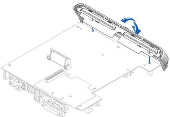
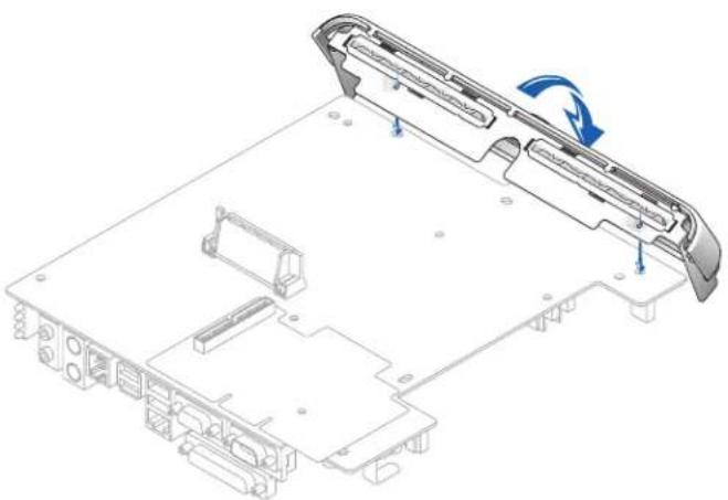
Technical line drawing of a computer chassis with labeled components and an arrow indicating rotation (no text or symbols present)15 Install the replacement system board and I/O shield assembly:
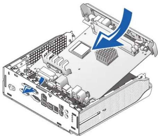
a Line up the parallel port connector with the opening on the back of the computer.
b Insert the back-panel connectors into the openings at the back of the computer and lower the system board into place.
natural_image
Illustration of an open computer drive chassis showing internal components and a blue arrow indicating compression or disassembly (no text or symbols present)Replacing the System Board 7



c Replace the five silver screws that you removed in step 10.
d Reinstall the heat sink retention base by reinserting the four green screws that you removed in step 9.
e Replace all of the components that you removed in step 8.
16 Reattach the stand (if used).
17 Attach the computer to the mounting plate (if used).
18 Replace the cable cover (if used).
NOTICE: To connect a network cable, first plug the cable in to the network wall jack and then in to the computer.
19 Connect your computer to the adapter cable and to an electrical outlet, connect any devices to electrical outlets, and then turn on the computer and devices.
After you replace the cover, the chassis intrusion detector, if enabled, causes the following message to appear on the screen at the next computer start-up:
ALERT! Cover was previously removed.
20 Reset the chassis intrusion detector by changing the Chassis Intrusion option to Enabled or Enabled-Silent.

0Y0561.book Page 9 Thursday, May 8, 2003 9:45 AM
Dell™ Computers
0Y0561.book Page 13 Thursday, May 8, 2003 9:45 AM

natural_image
Isometric view of a computer motherboard showing CPU socket, drive bays, and internal components (no text or labels)natural_image
Diagram of a device interior showing internal components and external structure (no text or symbols)






0Y0561.book Page 14 Thursday, May 8, 2003 9:45 AM

www.dell.com | support.dell.com
natural_image
Technical line drawing of a computer chassis with an arrow indicating a component (no text or symbols present)0Y0561.book Page 15 Thursday, May 8, 2003 9:45 AM

natural_image
Technical line drawing of a computer chassis with mounting hardware and a blue arrow indicating rotation (no text or symbols)natural_image
Illustration of a computer tower internal structure with a blue arrow indicating compression or disassembly (no text or symbols present)



0Y0561.book Page 17 Thursday, May 8, 2003 9:45 AM
Dell™ Computers
0Y0561.book Page 20 Thursday, May 8, 2003 9:45 AM

www.dell.com | support.dell.com
0Y0561.book Page 21 Thursday, May 8, 2003 9:45 AM

natural_image
Isometric view of a computer motherboard showing CPU socket, drive bays, and internal components (no text or labels)natural_image
Diagram of a device interior showing internal components and external structure (no text or symbols)0Y0561.book Page 22 Thursday, May 8, 2003 9:45 AM

www.dell.com | support.dell.com
natural_image
Technical line drawing of a computer chassis with an arrow indicating a component (no text or symbols present)0Y0561.book Page 23 Thursday, May 8, 2003 9:45 AM
natural_image
Technical line drawing of a computer chassis with labeled components and directional arrows indicating motion (no text or symbols present)natural_image
Illustration of an open computer drive chassis showing internal components and a blue arrow indicating compression or disassembly (no text or symbols present)ALERT! Cover was previously removed (Alerta. La cubierta se ha quitado anteriormente).
0Y0561.book Page 2 Thursday, May 8, 2003 9:45 AM



Printed in the U.S.A.
Brand : DELL
Model : OptiPlex SX270
Category : Desktop computer