Evoplus 80180 M - Pump DAB - Free user manual and instructions
Find the device manual for free Evoplus 80180 M DAB in PDF.
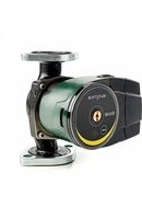
| Product type | Electronic variable speed circulator |
| Brand | DAB |
| Model | Evoplus 80180 M |
| Supply voltage | 1x220-240 V ±10%, 50/60 Hz |
| Protection rating (vertical) | IPX4D |
| Protection rating (horizontal) | IPX0D |
| Protection class | F |
| Liquid temperature | -10 °C to +110 °C |
| Max. ambient temperature | 40 °C |
| Max. operating pressure | 1.6 MPa (16 bar) |
| Min. operating pressure | 0.1 MPa (1 bar) |
| Max. head (Hmax) | Up to 18 m depending on model (see table) |
| Max. flow rate (Qmax) | Up to 66.64 m³/h depending on model |
| Sound level (Lpa) | ≤ 45 dB(A) |
| Control modes | Proportional pressure, constant pressure, constant curve, with temperature influence or external signal 0-10V/PWM |
| Communication | MODBUS RS-485, option LON Bus via interface |
| Logic inputs | IN1 (remote on/off), IN2 (economy mode) |
| Logic outputs | OUT1 (alarm), OUT2 (pump status) - NO/NC contacts 250V/5A |
| Twin function | Alternating, simultaneous or master/standby |
| Integrated protections | Overload, phase failure, overheating, overvoltage/undervoltage, dry running |
| Installation | Motor shaft horizontal, electronic housing vertical |
| Weight | Varies by model (see packaging label) |
| Body material | Cast iron (bronze version for domestic hot water) |
Frequently Asked Questions - Evoplus 80180 M DAB
User questions about Evoplus 80180 M DAB
0 question about this device. Answer the ones you know or ask your own.
Ask a new question about this device
Download the instructions for your Pump in PDF format for free! Find your manual Evoplus 80180 M - DAB and take your electronic device back in hand. On this page are published all the documents necessary for the use of your device. Evoplus 80180 M by DAB.
USER MANUAL Evoplus 80180 M DAB
2.1 Safety 20
2.2 Responsibility 20
2.3 Particular warnings 21
- Pumped liquids
- Applications 21
- Technical data 21
5.1 Electromagnetic Compatibility (EMC) 24
- Management 24
6.1 Storage 24
6.2 Transport 24
6.3 Weight 24
- Installation 24
7.1 Circular Installation and Maintenance 24
7.2 Rotation of the Motor Heads 25
7.3 Non-return valve 26
- Electrical connections 26
8.1 Power supply connection 27
8.2 Electrical connections of Inputs, Outputs and MODBUS 27
8.2.1 Digital Inputs 27
8.2.2 MODBUS and LON Bus 28
8.2.3 Analogue Input and PWM 28
8.2.4 Outputs 29
8.3 Connections for Twin Systems 29
9.Start 29
10. Functions 30
10.1 Regulating Modes 30
10.1.1 Regulation with Proportional Differential Pressure 30
10.1.2 Regulation with Constant Differential Pressure 30
10.1.3 Regulation with constant curve 30
10.1.4 Regulation with Constant and Proportional Differential Pressure depending on the Water Temperature 31
- Control Panel 31
11.1 Graphic Display 31
11.2 Navigation Buttons 31
11.3 Warning Lights 31
-
Menus 32
-
Factory settings 34
14.TypeS of Alarm 35 - Disposal 35
16.Error condition and reset 35
INDEX OF FIGURES
Figure 1: Assembly position 24
Figure 2: Instructions for motor head assembly 25
Figure 3: Installation on horizontal pipes 26
Figure 4: Electrical connections (front) 26
Figure 5: Electrical connections (rear) 26
Figure 6: Pull-out terminal board for supply. 27
Figure 7: Pull-out 13-pole terminal board: digital inputs and MODBUS 27
Figure 8: Pull-out 13-pole terminal board: 0-10V inputs and PWM ....28
Figure 9: Pull-out 6-pole terminal board: example of output connection . 29
Figure 10: Control panel 31
INDEX OF TABLES
Table 1: Maximum head (Hmax) and maximum flow rate (Qmax) of
EVOPLUS circulators 23
Table 2: Electrical connections 27
Table 3: Digital inputs IN1 and IN2 27
Table 4: RS_485 MODBUS terminals. 28
Table 5: Outputs OUT1 and OUT2 29
Table 6: Characteristics of the output contacts 29
Table 7: Factory settings. 35
Table 8: List of alarms. 35
GB ENGLISH

1. KEY
The frontispiece shows the version of this document in the form Vn.x. This version indicates that the document is valid for all software versions of the device n.y. For example: V3.0 is valid for all Sw: 3.y.
In this document the following symbols will be used to avoid situations of ranger:

Situation of general danger. Failure to respect the instructions that follow may cause harm to persons and property.

Situation of electric shock hazard. Failure to respect the instructions that follow may cause a situation of grave risk for personal safety.
2. GENERAL

Read this documentation carefully before installation.
Installation, electrical connection and commissioning must be carried out by specialised personnel, in compliance with the general and local safety regulations in force in the country in which the product is installed. Failure to respect these instructions not only causes risk to personal safety and damage to the equipment, but invalidates every right to assistance under guarantee.
The appliance is not intended to be used by persons (including children) with reduced physical, sensory or mental capacities, or who lack experience or knowledge, unless, through the mediation of a person responsible for their safety, they have had the benefit of supervision or of instructions on the use of the appliance. Children must be supervised to ensure that they do not play with the appliance.

Ensure that the product has not suffered any damage during transport or storage. Check that the outer casing is unbroken and in excellent conditions.
2.1 Safety
Use is allowed only if the electric system is in possession of safety precautions in accordance with the regulations in force in the country where the product is installed.
2.2 Responsibility
The Manufacturer does not vouch for correct operation of the machine or answer for any damage that it may cause if it has been tampered with, modified and/or run outside the recommended work range or in contrast with other indications given in this manual.
2.3 Particular warnings

Always switch off the mains power supply before working on the electrical or mechanical part of the system. Wait for the warning lights on the control panel to go out before opening the appliance. The capacitor of the direct current intermediate circuit remains charged with dangerously high voltage even after the mains power has been turned off.
Only firmly cabled mains connections are admissible.
pliance must be earthed (IEC 536 class 1, NEC and other applicable standards).

Mains terminals and motor terminals may still have dangerous voltage when the motor is stopped.

If the power cable is damaged, it must be replaced by the technical assistance service or by qualified personnel, so as to avoid any risk.
3. PUMPED LIQUIDS
The machine has been designed and made for pumping water, free from explosive substances and solid particles or fibres, with a density of 1000 Kg / m^3 , a kinematic viscosity of 1mm^2 /s and non chemically aggressive liquids. It is possible to use ethylene glycol in a percentage of no more than 30% .
4. APPLICATIONS
EVOPLUS series circulators allow integrated adjustment of the differential pressure which enables the circulator performance to be adapted to the actual requirements of the system. This determines considerable energy saving, a greater possibility of control of the system, and reduced noise.
EVOPLUS circulators are designed for the circulation of:
- water in heating and conditioning systems.
- water in industrial water circuits.
- domestic water only for the versions with bronze pump body.
EVOPLUS circulators are self-protected against:
- Over loads
Lack of phase
Excess temperature -
Over-voltage and under-voltage
-
TECHNICAL DATA
| The supply voltage 1x220-240 V (+/-10%), 50/60 Hz | |
| Absorbed power See electrical data plate | |
| Maximum current See electrical data plate | |
| Grade of protection (electronic control device in vertical position) IPX4D | |
| Grade of protection (electronic control device in horizontal position) IPX0D | |
| Protection class F | |
| TF Class TF 110 | |
| Motor protector | No external motor protector is needed |
| Maximum environment temperature 40 °C | |
| Liquid temperature | -10 °C ÷ 110 °C |
| Flow rate | See Table 1 |
| Head | See Table 1 |
| Maximum working pressure | 1.6 MPa |
| Minimum working pressure | 0.1 MPa |
| Lpa [dB(A)] | <= 45 |
| EVOPLUS Hmax [m] Qmax [m3/h] | EVOPLUS Hmax [m] | Qmax [m3/h] | |||
| B 120/220.32 M | 12.0 17.01 D | 120/220.32 M 12.0 | 30.62 | ||
| B 120/220.32 SAN M* | |||||
| B 40/220.40 M 4.0 12.18 D 40/220.40 | M 4.0 21.91 | ||||
| B 60/220.40 M 6.0 15.69 D 60/220.40 | M 6.0 28.24 | ||||
| B 80/220.40 M 8.0 18.58 D 80/220.40 | M 8.0 33.44 | ||||
| B 100/220.40 M 10.0 20.64 D 100/220.40 | .40 M 10.0 37.15 | ||||
| B 120/250.40 M | 12.0 23.48 D | 120/250.40 M 12.0 | 42.26 | ||
| B 120/250.40 SAN M* | |||||
| B 150/250.40 M | 15.0 25.65 D | 150/250.40 M 15.0 | 46.17 | ||
| B 150/250.40 SAN M* | |||||
| B 180/250.40 M | 18.0 25.65 D | 180/250.40 M 18.0 | 46.17 | ||
| B 180/250.40 SAN M* | |||||
| B 40/240.50 M 4.0 20.27 D 40/240.50 | M 4.0 36.49 | ||||
| B 60/240.50 M 6.0 25.20 D 60/240.50 | M 6.0 45.36 | ||||
| B 80/240.50 M 8.0 27.51 D 80/240.50 | M 8.0 49.52 | ||||
| B 100/280.50 M | 10.0 30.08 D | 100/280.50 M 10.0 | 54.14 | ||
| B 100/280.50 SAN M* | |||||
| B 120/280.50 M | 12.0 32.98 D | 120/280.50 M 12.0 | 59.36 | ||
| B 120/280.50 SAN M* | |||||
| B 150/280.50 M | 15.0 35.02 D | 150/280.50 M 15.0 | 63.04 | ||
| B 150/280.50 SAN M* | |||||
| B 180/280.50 M | 18.0 37.02 D | 180/280.50 M 18.0 | 66.64 | ||
| B 180/280.50 SAN M* | |||||
| B 40/340.65 M | 4.0 27.90 D | 40/340.65 M 4.0 50. | 22 | ||
| B 40/340.65 SAN M* |
ENGLISH
GB
Table 1: Maximum head (Hmax) and maximum flow rate (Qmax) of EVOPLUS circulators
| B 60/340.65 M B 60/340.65 SAN M* | 6.0 34.47 D | 60/340.65 M 6.0 62.05 | |||
| B 80/340.65 M B 80/340.65 SAN M* | 8.0 38.30 D | 80/340.65 M 8.0 68.94 | |||
| B 100/340.65 M B 100/340.65 SAN M* | 10.0 41.71 D | 100/340.65 M 10.0 75.08 | |||
| B 120/340.65 M B 120/340.65 SAN M* | 12.0 44.63 D | 120/340.65 M 12.0 80.33 | |||
| B 150/340.65 M B 150/340.65 SAN M* | 15.0 53.44 D | 150/340.65 M 15.0 96.19 | |||
| B 40/360.80 M 4.0 37.30 D 40/360.80 | M 4.0 67.14 | ||||
| B 60/360.80 M 6.0 43.54 D 60/360.80 | M 6.0 78.37 | ||||
| B 80/360.80 M 8.0 42.84 D 80/360.80 | M 8.0 77.11 | ||||
| B 100/360.80 M 10.0 49.02 D 100/360.80 | M 8.0 10.0 88.24 | ||||
| B 120/360.80 M 12.0 58.12 D 120/360.80 | M 12.0 104.62 | ||||
| B 40/450.100 M 4.0 45.29 D 40/450.10 | M 4.0 81.52 | ||||
| B 60/450.100 M 6.0 50.77 D 60/450.10 | M 6.0 91.39 | ||||
| B 80/450.100 M 8.0 56.85 D 80/450.10 | M 8.0 102.33 | ||||
| B 100/450.100 M | 10.0 | 61.60 | D 100/450.100 M | 10.0 | 110.88 |
| B 120/450.100 M | 12.0 | 63.73 | D 120/450.100 M | 12.0 | 114.71 |
*This circulator is suitable for drinking water only.
GB ENGLISH
5.1 Electromagnetic Compatibility (EMC)
EVOPLUS circulators respect standard EN 61800-3, in the C2 category, for electromagnetic compatibility.
- Electromagnetic emissions - Industrial environment (in some cases restrictive measures may be requested).
- Conducted emissions - Industrial environment (in some cases restrictive measures may be requested).
6. MANAGEMENT
6.1 Storage
All the circulators must be stored in a dry covered place, with possibly constant air humidity, free from vibrations and dust. They are supplied in their original pack in which they must remain until the time of installation. If this is not the case, accurately close the suction and delivery mouth.
6.2 Transport
Avoid subjecting the products to needless impacts and collisions. To lift and transport the circulator use lifting devices with the aid of the pallet supplied with it (if contemplated).
6.3 Weight
The adhesive plate on the packaging indicates the total weight of the circulator.
7. INSTALLATION
Carefully follow the advice in this chapter to carry out correct electrical, hydraulic and mechanical installation.

Always switch off the mains power supply before working on the electrical or mechanical part of the system. Wait for the warning lights on the control panel to go out before opening the appliance. The capacitor of the direct current intermediate circuit remains charged with dangerously high voltage even after the mains power has been turned off.
Only firmly cabled mains connections are admissible. The appliance must be earthed (IEC 536 class 1, NEC and other applicable standards).
Ensure that the voltage and frequency on the data plate of the EVOPLUS circulator are the same as those of the power mains.
7.1 Circular Installation and Maintenance
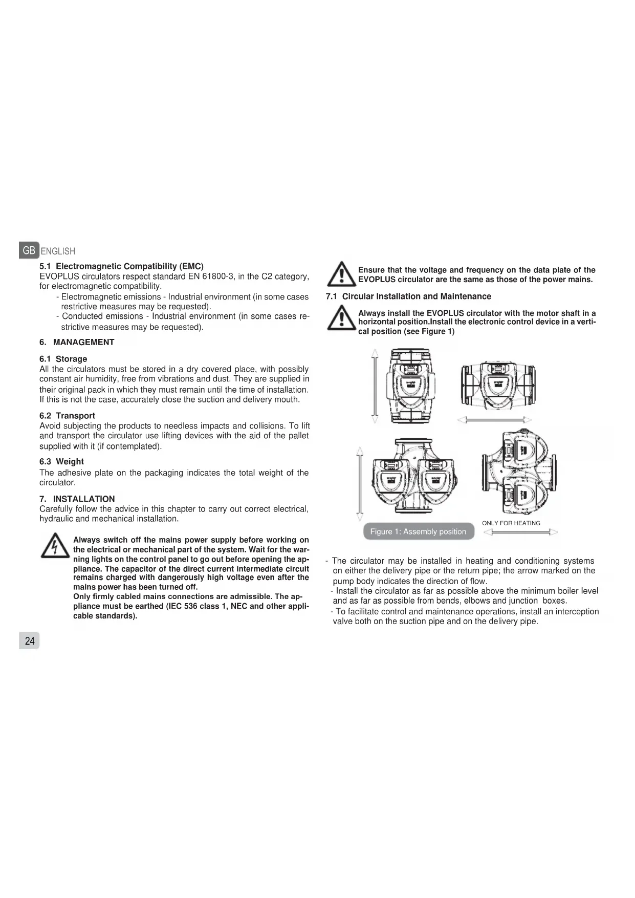
Always install the EVOPLUS circulator with the motor shaft in a horizontal position. Install the electronic control device in a vertical position (see Figure 1)

- The circulator may be installed in heating and conditioning systems on either the delivery pipe or the return pipe; the arrow marked on the pump body indicates the direction of flow.
- Install the circulator as far as possible above the minimum boiler level and as far as possible from bends, elbows and junction boxes.
-
To facilitate control and maintenance operations, install an interception valve both on the suction pipe and on the delivery pipe.
-
Before installing the circulator, accurately flush the system with only water at 80^ . Then drain the system completely to eliminate any harmful substance that may have got into circulation.
- Assemble in such a way as to avoid dripping on the motor and on the electronic control device during both installation and maintenance.
- Avoid mixing additives derived from hydrocarbons and aromatic products with the circulating water. It is recommended that the addition of antifreeze, where necessary, should not exceed 30% .
- In the event of heat insulation use the special kit (if provided) and ensure that the condensate draining holes in the motor casing are not closed or partly blocked.
- To guarantee maximum efficiency of the system and long life of the circulator it is recommended to use magnetic sludge-removing filters to separate and collect any impurities present in the system (particles of sand, particles of iron and sludge)

Never insulate the electronic control device.
- In the case of maintenance, always use a set of new gaskets.
7.2 Rotation of the Motor Heads
If the circulator is installed on pipes in a horizontal position, it will be necessary to rotate the motor with the respective electronic device through 90 degrees in order to maintain the grade of IP protection and to allow the user a more convenient interaction with the graphic interface (see Figure 2).

Before rotating the circulator, ensure that it has been completely drained.
Should it be necessary to rotate the motor heads, follow the instructions below with care to ensure correct installation:
- Unscrew the 4 screws fixing the motor assembly to the pump body (figure A).
-
- Rotate the motor assembly keeping it in the seat where it couples with the pump body (figure A-B).
- Once the head has been rotated into the desired position, tighten the 4 screws, always proceeding in cross formation (figure C).
If the motor assembly has been removed from its seat, pay the greatest attention during assembly, taking care to insert the impeller completely in the floating ring before tightening the retaining screws (figure D). If it has been correctly assembled, the motor assembly rests completely on the pump body.

Incorrect assembly may damage the impeller, causing a typical rubbing noise when the circulator starts.


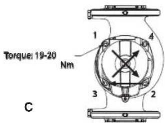
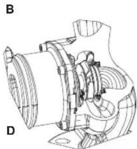
Figure 2: Instructions for motor head assembly

The electronic control device must always remain in vertical position!
GB
ENGLISH

Ensure that the connecting cable of the pressure sensor never comes in contact with the motor casing.

Figure 3: Installation on horizontal pipes
7.3 Non-return valve
If the system is equipped with a non-return valve, ensure that the minimum pressure of the circulator is always higher than the valve closing pressure.
8. ELECTRICAL CONNECTIONS
The electrical connections must be made by expert, qualified personnel.

ATTENTION! ALWAYS RESPECT THE LOCAL SAFETY REGULATIONS.

Always switch off the mains power supply before working on the electrical or mechanical part of the system. Wait for the warning lights on the control panel to go out before opening the appliance. The capacitor of the direct current intermediate circuit remains charged with dangerously high voltage even after the mains power has been turned off.
Only firmly cabled mains connections are admissible. pliance must be earthed (IEC 536 class 1, NEC and other appliccable standards).

THE SYSTEM MUST BE CORRECTLY AND SAFELY EARTHED!

It is recommended to install a differential switch to protect the system, which must have correct dimensions, such as: Class 10A with adjustable leakage current, selective, protected against sudden tripping.
The automatic differential switch must be marked with the following two symbols:

- The circulator does not require any external motor protection.
- Ensure that the supply voltage and frequency are the same as the values indicated on the electrical data plate of the circulator.
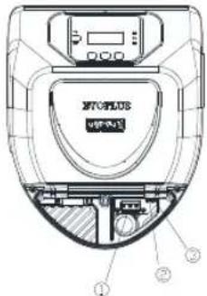

Figure 4: Electrical connections (front)
gure 5: Electrical connections (rear)
Table 2: Electrical connections
| Reference (Figure 4 and Figure 5) | Description |
| 1 | Pull-out terminal board for connection of the supply line: 1x220-240 V, 50/60 Hz |
| 2 auxiliary LED | |
| 3 system live indicating LED | |
| 4 Connector for connecting twin circulators | |
| 5 | Connector for connecting the fluid pressure and temper sensor (standard) |
| 6 | Pull-out 13-pole terminal board for connecting the inputs and the MODBUS systems |
| 7 | Pull-out 6-pole terminal board for alarm signals and system status |
8.1 Power supply connection

Figure 6: Pull-out terminal board for supply
Before supplying power to the circulator, ensure that the cover of the EVOPLUS control panel is perfectly closed
8.2 Electrical connections of Inputs, Outputs and MODBUS
EVOPLUS circulators are equipped with digital and analogue inputs and digital outputs so as to be able to realise interface solutions with more complex installations.
For the installer it will be sufficient to wire up the desired input and output contacts and to configure their functions as desired (see par. par. 8.2.1 par. 8.2.2 par. 8.2.3 and par. 8.2.4)
8.2.1 Digital Inputs

Figure 7: Pull-out 13-pole terminal board: digital inputs and MODBUS
With reference to Figure 7 the digital inputs available are:
Table 3: Digital inputs IN1 and IN2
| Input | Terminal no. | Type of contact | Associated function |
| IN1 | 12 | Clean contact | EXT: If is activated from the control panel (see par. 12 Page 11.0 of the EVOPLUS menu) it will be possible to command the switching on and off of the pump in remote mode. |
| 13 | |||
| IN2 | 10 | Clean contact | Economy: If is activated from the control panel (see par. 12 Page 5.0 of the EVOPLUS menu) it will be possible to active the set-point reduction function in remote mode. |
| 11 |
GB ENGLISH
If the EXT and Economy functions have been activated from the control panel, the system will behave as follows:
| IN1 IN2 System Status |
| Open Open Pump stopped |
| Open Closed Pump stopped |
| Closed Open Pump running with set-point set by the user |
| Closed Closed Pump running with reduced set-point |
8.2.2 MODBUS and LON Bus
EVOPLUS circulators provide serial communication through an input RS-485. The communication is realised according to MODBUS specifications.
With MODBUS it is possible to set the circulator operating parameters in remote mode such as, for example, the desired differential pressure, the influence of temperature, the regulating mode, etc. At the same time the circulator can provide important information on the system status.
For the electrical connections refer to Figure 6 and to Table 4:
Table 4: RS 485 MODBUS terminals
| MODBUS Terminals | Terminal no. | Description |
| A | 2 Terminal not inverted (+) | |
| B | 1 | Terminal inverted (-) |
| Y | 3 | GND |
The MODBUS communication configuration parameters are available in the advanced menu see Par.12).
EVOPLUS circulators also have the possibility of communicating on LON bus through external interface devices.
Further information and details on the MODBUS and LON bus interface are available at the following link:
http://www.dabpumps.com/evoplus

8.2.3 Analogue Input and PWM
Figure 8: Pull-out 13-pole terminal board: 0-10V inputs and PWM
Figure 8 shows the wiring diagram of the external signals 0-10V and PWM. As may be seen from the figure the 2 signals share the same terminals on the terminal board, so they are mutually exclusive. If you want to use an analogue control signal, you will have to set the type of signal from the menu (see par. 12 Page 7.0).
Further information and details on the MODBUS and LON bus interface are available for download at the following link:
http://www.dabpumps.com/evoplus
8.2.4 Outputs

Figure 9: Pull-out 6-pole terminal board: example of output connection
With reference to Figure 9 the digital outputs available are:
| Output Terminal no. | Type of contact | Associated function | |
| OUT1 | 1 | NC | Presence/Absence of alarms in the system |
| 2 | COM | ||
| 3 | NO | ||
| OUT2 | 4 | NC | Pump running/Pump stopped5 |
| 6 | NO | ||
Table 5: Outputs OUT1 and OUT2
The outputs OUT1 and OUT2 are available on the pull-out 6-pole terminal board as specified in Table 5 which also shows the type of contact (NC = Normally Closed, COM = Common, NO = Normally Open). The electrical characteristics of the contacts are shown in Table 6.
In the example shown in Figure 8 the light L1 is lit when there is an alarm in the system and it goes off when no kind of malfunction is found, whereas the light L2 is lit when the pump is running and goes off when
the pump is stopped.
Table 6: Characteristics of the output contacts
| Characteristics of the output contacts | |
| Max. bearable voltage [V] 250 | |
| Max. bearable current [A] | 5 If resistive load 2,5 If inductive load |
| Max. accepted cable section [mm²] 2,5 | |
8.3 Connections for Twin Systems
For correct operation of the twin system, all the external connections of the pull-out 13-pole terminal board must be connected in parallel between the 2 EVOPLUS respecting the numbering of the individual terminals.
For the possible operating modes of twin systems see par. 12 Page 8.0 of the EVOPLUS menu.
9. START

All the starting operations must be performed with the cover of the EVOPLUS control panel closed.
Start the system only when all the electrical and hydraulic connections have been completed.
Avoid running the circulator when there is no water in the system.

As well as being at a high temperature and pressure, there is in the system may also be in the form of steam. DANGER OF SCALDING!
It is dangerous to touch the circulator. DANGER OF SCALDING!
Once all the electrical and hydraulic connections have been made, fill the system with water and if necessary with glycol (for the maximum glycol percentage see par. 3) and feed the system.
Once the system has been started it is possible to modify the operating modes to adapt better to the plant requirements (see par.12).
10. FUNCTIONS
10.1 Regulating Modes
EVOPLUS circulators allow the following regulating modes depending on plant requirements:
- Proportional differential pressure regulation depending on the flow present in the plant.
- Proportional differential pressure regulation with set-point depending on the external signal 0-10V or PWM.
- Proportional differential pressure regulation depending on the flow present in the plant and on the liquid temperature.
- Constant differential pressure regulation.
- Constant differential pressure regulation with set-point depending on the external signal 0-10V or PWM.
- Constant differential pressure regulation with variable set-point depending on the liquid temperature.
- Regulation with constant curve.
- Regulation with constant curve with rotation speed depending on the external signal 0-10V or PWM.
The regulating mode may be set through the EVOPLUS control panel (see par. 12 Page 2.0).
10.1.1 Regulation with Proportional Differential Pressure

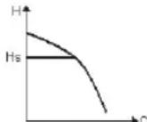
In this regulating mode the differential pressure is reduced or increased as the demand for water decreases or increases.
The Hs set point may be set from the display or by an external signal 0-10V or PWM.
Regulation indicated for:
- Heating and conditioning plants with high load losses
- Two-pipe systems with thermostatic valves and head ≥ 4m
- Plants with secondary differential pressure regulator
- Primary circuits with high load losses
- Domestic water recirculating systems with thermostatic valves on the rising columns
10.1.2 Regulation with Constant Differential Pressure
In this regulating mode the differential pressure is kept constant, irrespective of the demand for water, The Hs set point may be set from the display or by an external signal 0-10V or PWM.
Regulation indicated for:
- Heating and conditioning plants with low load losses
- Two-pipe systems with thermostatic valves and head ≤ 2m
- Single-pipe systems with thermostatic valves
- Plants with natural circulation
-
Primary circuits with low load losses
-
Domestic water recirculating systems with thermostatic valves on the rising columns.
10.1.3 Regulation with constant curve
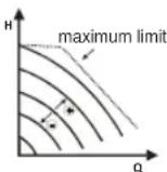
In this regulating mode the circulator works on characteristic curves at a constant speed. The operating curve is selected by setting the rotation speed through a percentage factor. The value 100% indicates the maximum limit curve. The actual rotation speed may depend on the power and differential pressure limits of your circulator model.
The rotation speed may be set from the display or by an external signal 0-10V or PWM.
Regulation indicated for heating and conditioning plants with constant flow.
10.1.4 Regulation with Constant and Proportional Differential Pressure depending on the Water Temperature

In this regulating mode the regulating set point Hs is reduced or increased according to the water temperature. THs may be set from 0^ to 100^ in order to allow operation in both heating and conditioning plants.
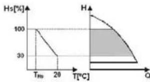
Regulation indicated for:
-
Plants with variable flow (two-pipe heating plants), where a further reduction of the circulator performance is ensured depending on the lowering of the temperature of the circulating liquid, when the demand for heating is lower.
-
Plants with constant flow (single-pipe and underfloor heating plants), where the circulator performance can be regulated only by activating the temperature influence function.
11. CONTROL PANEL
The functions of EVOPLUS circulators can be modified by means of the control panel on the cover of the electronic control device.
On the panel there are: a graphic display, 4 navigation keys and 3 LED warning lights (see Figure 10).
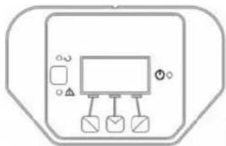
Figure 10: Control panel
11.1 Graphic Display
Using the graphic display it will be possible to navigate in an easy and intuitive menu which will enable you to check and modify the system operating mode, the enabling of the inputs and the working set-point. It will also be possible to view the system status and the log of any alarms memorised by the system.
11.2 Navigation Buttons
4 buttons are provided for navigating in the menu: 3 buttons under the display and 1 at the side. The buttons under the display are called active buttons and the one at the side is called hidden button.
Each page of the menu is made in such a way as to indicate the function associated with the 3 active buttons (the ones under the display).
11.3 Warning Lights
Yellow light: System live signal.
If lit, it means that the system is live.

Never remove the cover if the yellow light is lit.
Red light: Warning of an alarm/malfunction present in the system.
If the light is blinking it is a non-blocking alarm and the pump can still be controlled. If the light is fixed it is a blocking alarm and the pump cannot be controlled.
Green light: Pump ON/OFF signal.
if lit, the pump is running. If off, the pump is stopped.
GB ENGLISH
12. MENUS
EVOPLUS circulators offer 2 menus: user menu and advanced menu.
The user menu is accessible from the Home Page by pressing and releasing the central "Menu" button.
The user menu is accessible from the Home Page by holding down the central "Menu" button for 5 seconds
Below are shown the user menu pages with which it is possible to check the system status and modify its settings.
Instead on the advanced menu there are the configuration parameters for communication with MODBUS systems (for further details visit the link: http://www.dabpump.com/evoplus). To leave the advanced menu you must scroll through all the parameters using the central button.
If the menu pages show a key at bottom left it means that it is not possible to change the settings. To unblock the menus go to the Home Page and press the hidden button and the button under the key at the same time until the key disappears.
If no button is pressed for 60 minutes, the settings are automatically blocked and the display switches off. When any button is pressed the display lights up again and the "Home Page" appears.
To navigate in the menus, press the central button.
To return to the previous page, hold down the hidden button, then press and release the central button.
To modify the settings use the left and right buttons.
To confirm the change of a setting, hold down the central button "OK"
for 3 seconds. Confirmation will be indicated by the following icon:
| Home Page H: 12.0m Mend | The main settings of the system are graphically summed up on the Home Page. The icon at top left indicates the type of regulation selected. The icon at centre top indicates the operating mode selected (auto or economy). The icon at top right indicates the presence of a single ① or twin inverter. ②/① The rotation of the icon ① or ② indicates which circulation pump is operating. At the centre of the Home Page is a read-only parameter which can be chosen from a small set of parameters on Page 9.0 of the menu. From the Home Page it is possible to access the page for regulating the contrast of the display: hold down the hidden button, then press and release the right button. EVOPLUS circulators offer 2 menus: user menu and advanced menu. The user menu is accessible from the Home Page by pressing and releasing the central "Menu" button. The user menu is accessible from the Home Page by holding down the central "Menu" button for 5 seconds. |
| Page 1.0 Default OK ↓ OK | The factory settings are set from Page 1.0 by holding down the left and right buttons at the same time for 3 seconds. The resetting of the factory settings will be notified by the appearance of the symbol ↓ next to the word "Default". |

| Page 2.0 Hs: 50 °C - ↓OK + | The regulating mode is set from Page 2.0. You can choose between the following modes: 1 = Proportional differential pressure regulation. 2 = Proportional differential pressure regulation with set-point set by external signal (0-10V or PWM). 3 = Proportional differential pressure regulation with set-point depending on temperature. 4 = Regulation with constant differential pressure. 5 = Constant differential pressure regulation with set-point set by external signal (0-10V or PWM). 6 = Constant differential pressure regulation with set-point depending on temperature. 7 = Regulation with constant curve with rotation speed set from the display. 8 = Regulation with constant curve with rotation speed set by an external signal (0-10V or PWM). Page 2.0 displays 3 icons which represent: - central icon = setting currently selected - right icon = next setting - left icon = previous setting |
| Page 3.0 Hs: 12.0 m - ↓ OK + | The regulating set-point can be modified from Page 3.0. Depending on the type of regulation chosen on the previous page, the set-point to be set will be a head or, in the case of a Constant Curve, a percentage of the rotation speed. ②/① |
| Page 4.0 Hs: 50 °C - ↓ OK + | ③+④ge 4.0 it is possible to modify the parameter THs with which to make the curve depending on temperature (see Par. 10.1.4). This page will be displayed only for the regulating modes de-p2+⑥on fluid temperature |
| Page 5.0 auto ← ↓OK → | Page 5.0 allows you to set the "auto" or "economy" operating mode. "Auto" mode disables the reading of the status of digital input IN2 and in fact the system always activates the set-point set by the user. "Economy" mode enables the reading of the status of digital input IN2. When input IN2 is energised the system activates a percentage reduction of the set-point set by the user (Page 6.0 of the EVOPLUS menu). For the connection of the inputs see par. 8.2.1 |
| Page 6.0 E: 50% → ↓OK + | Page 6.0 is displayed if "economy" mode has been chosen on page 5.0 and allows setting of the percentage value of the set-point. This reduction will be carried out if digital input IN2 is energised. |
| Page 7.0 PWM ↑ ↓ OK ↓ + | Page 7.0 is displayed if an operating mode has been chosen with set-point regulated by an external signal. This page allows you to choose the type of control signal: analogue 0-10V (positive or negative increase) or PWM (positive or negative increase). |
| Page 8.0 ← ↓ OK → | If a twin system is used (see Par. 8.3) on page 8.0 you can set one of the 3 possible twin operation modes: Alternate every 24h: The 2 circulators alternate in regulation every 24 operating hours. If one of the 2 malfunctions, the other takes over regulation. Simultaneous: The 2 circulators work at the same time and at the same speed. This mode is useful when a flow rate is required that cannot be provided by a single pump. Main/Reserve: Regulation is always performed by the same circulator (Main), the other (Reserve) takes over only if there is a malfunction of the Main one. If the twin communication cable is disconnected the systems automatically figure as Single, working completely independent of each other. |
| Page 9.0 EQUSETPhT1 H:12.0m ←▼OK→ | On page 9.0 it is possible to choose the parameter to be displayed on the Home Page: H: Measured head expressed in metres Q: Estimated flow rate expressed in m3/h S: Rotation speed expressed in revs per minute (rpm) E: Head requested by external signal 0-10V or PWM, if active P: Power distributed expressed in kW h: Operating hours T: Liquid temperature measured with the sensor fitted on board T1: Liquid temperature measured with an external sensor |
| Page 10.0 DEU ITA ENG ←▼OK→ | On page 10.0 you can choose the language in which to display the messages. |
| Page 11.0 ←▼OK→ | On page 11.0 you can display the alarms log by pressing the right button. |
| Alarms Log e15 Pompaccata | If the system finds any faults it records them permanently in the alarms log (up to a maximum of 15 alarms). For each recorded alarm a page composed of 3 parts is displayed: an alphanumeric code that identifies the type of fault, a symbol that illustrates the fault in graphic mode, and a message in the language selected on Page 10.0, giving a brief description of the fault. By pressing the right button you can scroll through all the pages of the log. 2 questions appear at the end of the log: “Reset Alarms?” Pressing OK (left button) resets any alarms still present in the system. “Delete Alarms Log?” Pressing OK (left button) deletes the alarms memorised in the log. |
| Pagina 12.0 ON OFF EXT → ↓ OK | On page 12.0 you can set the system status in ON, OFF or controlled by a remote signal EXT (digital input IN1). If ON is selected the pump is always on. If OFF is selected the pump is always off. If EXT is selected, reading of the status of digital input IN1 is enabled. When input IN1 is energised the system goes ON and the pump is started (on the Home Page the messages “EXT” and “ON” appear alternately at bottom right); when input IN1 is not energised the system goes OFF and the pump goes off (on the Home Page the messages “EXT” and “OFF” appear alternately at bottom right). For the connection of the inputs see par. 8.2.1 |
- FACTORY SETTINGS
| Parameter Value | |
| Regulating mode | \( \updownarrow_{+} = \)Proportional differential pressure regulation |
| THs 50 °C | |
| Operating mode auto |
Table 7: Factory settings
| Set-point reduction percentage 50 % | |
| Type of external analogue signal 0-10V | |
| Twin operating mode = Alternate every 24h | |
| Pump start control EXT (from remote signal on input IN1). | |
- TYPES OF ALARM
Tabella 8: Elenco allarmi
| Alarm Code Alarm | Symbol Alarm Description | |
| e0 - e16; e21 Internal Error | ||
| e17 - e19 Short Circuit | ||
| e20 Voltage Error | max | |
| e22 - e31 Internal Error | ||
| e32 - e35 Electronic system Excess temperature | ||
| e37 Low voltage | min | |
| e38 High voltage | max | |
| e39 - e40 Pump blocked | ||
| e43; e44; e45; e54 Pressure Sensor | ||
| e46 Pump Disconnected | ||
| e42 Dry operation | ||
| e56 | Motor excess temperature (motor protector trips) | |
| e57 | Frequency of PWM external signal less than 100 Hz | |
| e58 | Frequency of PWM external signal greater than 5 kHz | |
ENGLISH
15.DISPOSAL
This product or any part of it must be disposed of correctly:
- Use public or private local systems for waste collection.
- If that is not possible, contact Dab Pumps or the nearest authorised service workshop.
INFORMATION
Frequently asked questions (faq) on the ecodesign directive 2009/125/ ec establishing a framework for the setting of ecodesign requirements for energy-related products and its implementing regulations: http:// ec.europa.eu/enterprise/policies/sustainable-business/documents/ eco-design/guidance/files/20110429_faq_en.pdf
Guidelines accompanying commission regulations implementing the ecodesign directive: http://ec.europa.eu/energy/efficiency/ecodesign/ legislation_en.htm - see "circulators"
- ERROR CONDITION AND RESET
| Display Indica-tion | Description | Reset | |
| e0 - e16 | Internal error | - Switch off system power.- Wait for the warning lights on the control panel to go off, then power the system again.- If the error persists, change the circulator. | |
| e37 | Low mains voltage (LP) | - Switch off system power.- Wait for the warning lights on the control panel to go off, then power the system again.- Check that the mains voltage is correct, if ne-cessary reset it at the plate values | |
| e38 | High mains voltage (HP) | - Switch off system power.- Wait for the warning lights on the control panel to go off, then power the system again.- Check that the mains voltage is correct, if ne-cessary reset it at the plate values. | |
| e32-e35 |  | Critical overhea- ting of electronic parts | - Switch off system power. - Wait for the warning lights on the control panel to go off. - Check that the system ventilation ducts are not blocked and that the environment tempe- rature of the premises is correct. |
| e43-e45; e54 |  | Sensor signal absent | - Check sensor connection. - If the sensor is faulty, replace it. |
| e39-e40 |  | Protection against overcurrent | - Check that the circulator turns freely. - Check that any antifreeze added does not exceed the maximum percentage of 30%. |
| e21-e30 |  | Voltage Error | - Switch off system power. - Wait for the warning lights on the control panel to go off, then power the system again. - Check that the mains voltage is correct, if ne- cessary reset it at the plate values. |
| e31 |  | Twin com- munication absent | - Check that the twin communication cable is intact. - Check that both circulators are powered. |
| e42 |  | Dry opera- tion | - Put the system under pressure. |
| e56 |  | Motor excess tem- perature | - Switch off system power. - Wait for the motor to cool down. - Power the system again. |
| e57 ; e58 |  | \( \mathrm{f} < {100}\mathrm{\;{Hz}} \) ; \( \mathrm{f} > 5\mathrm{{kHz}} \) | Check that the PWM external signal is operating and connected as specified. |
| Energy Efficiency Index - EEI | |||
| EVOPLUS B 120/220.32 M | 0,22 | EVOPLUS D 120/220.32 M | 0,22 |
| EVOPLUS B 40/220.40 M | 0,23 | EVOPLUS D 40/220.40 M | 0,23 |
| EVOPLUS B 60/220.40 M | 0,23 | EVOPLUS D 60/220.40 M | 0,23 |
| EVOPLUS B 80/220.40 M | 0,21 | EVOPLUS D 80/220.40 M | 0,23 |
| EVOPLUS B 100/220.40 M | 0,20 | EVOPLUS D 100/220.40 M | 0,23 |
| EVOPLUS B 120/250.40 M | 0,20 | EVOPLUS D 120/250.40 M | 0,23 |
| EVOPLUS B 150/250.40 M | 0,20 | EVOPLUS D 150/250.40 M | 0,23 |
| EVOPLUS B 180/250.40 M | 0,20 | EVOPLUS D 180/250.40 M | 0,23 |
| EVOPLUS B 40/240.50 M | 0,23 | EVOPLUS D 40/240.50 M | 0,23 |
| EVOPLUS B 60/240.50 M | 0,21 | EVOPLUS D 60/240.50 M | 0,22 |
| EVOPLUS B 80/240.50 M | 0,21 | EVOPLUS D 80/240.50 M | 0,22 |
| EVOPLUS B 100/280.50 M | 0,20 | EVOPLUS D 100/280.50 M | 0,22 |
| EVOPLUS B 120/280.50 M | 0,19 | EVOPLUS D 120/280.50 M | 0,22 |
| EVOPLUS B 150/280.50 M | 0,19 | EVOPLUS D 150/280.50 M | 0,21 |
| EVOPLUS B 180/280.50 M | 0,19 | EVOPLUS D 180/280.50 M | 0,21 |
| EVOPLUS B 40/340.65 M | 0,21 | EVOPLUS D 40/340.65 M | 0,21 |
| EVOPLUS B 60/340.65 M | 0,20 | EVOPLUS D 60/340.65 M | 0,21 |
| EVOPLUS B 80/340.65 M | 0,19 | EVOPLUS D 80/340.65 M | 0,21 |
| EVOPLUS B 100/340.65 M | 0,18 | EVOPLUS D 100/340.65 M | 0,20 |
| EVOPLUS B 120/340.65 M | 0,18 | EVOPLUS D 120/340.65 M | 0,20 |
| EVOPLUS B 150/340.65 M | 0,18 | EVOPLUS D 150/340.65 M | 0,20 |
| EVOPLUS B 40/360.80 M | 0,19 | EVOPLUS D 40/360.80 M | 0,20 |
| EVOPLUS B 60/360.80 M | 0,20 | EVOPLUS D 60/360.80 M | 0,20 |
| EVOPLUS B 80/360.80 M | 0,20 | EVOPLUS D 80/360.80 M | 0,20 |
| EVOPLUS B 100/360.80 M | 0,19 | EVOPLUS D 100/360.80 M | 0,19 |
| EVOPLUS B 120/360.80 M | 0,19 | EVOPLUS D 120/360.80 M | 0,19 |
| EVOPLUS B 40/450.100 M | 0,19 | EVOPLUS D 40/450.100 M | 0,19 |
| EVOPLUS B 60/450.100 M | 0,18 | EVOPLUS D 60/450.100 M | 0,19 |
| EVOPLUS B 80/450.100 M | 0,18 | EVOPLUS D 80/450.100 M | 0,20 |
| EVOPLUS B 100/450.100 M | 0,19 | EVOPLUS D 100/450.100 M | 0,20 |
| EVOPLUS B 120/450.100 M | 0,19 | EVOPLUS D 120/450.100 M | 0,20 |
The benchmark for the most efficient circulators is EE1 ≤ 0,20
FRANCAIS
FR
INDEX
2.2 Responsibilities
Units 4 & 5, Stortford Hall Industrial Park,
Dunmow Road, Bishop's Stortford, Herts
CM23 5GZ - UK
salesuk@dwtgroup.com
Tel.: +44 1279 652 776
Fax:+441279657727
DAB PUMPS IBERICA S.L.
Avenida de Castilla nr.1 Local 14
28830 - San Fernando De
Henares - Madrid Spain
info.spain@dwtgroup.com
Ph.: +34 91 6569545
Fax:+34916569676
DAB PUMPS B.V.
Brusselslaat 150
info.belgium@dwtgroup.com
Tel.: +32 2 4668353
Fax:+3224669218
DAB PUMPS B.V.
info.usa@dwtgroup.com
Ph. :1-843-824-6332
Toll Free:1-866-896-4DAB (4322)
Fax :1-843-797-3366
DWT South Africa
Podium at Menlyn, 3rd Floor, Unit 3001b, 43 Ingersol Road, C/O Lois and Atterbury,
Menlyn, Pretoria, 0181, South-Africa
info.sa@dwtgroupp.com
Tel: +27 12 361 3997
Fax: +27 12 361 3137
OOO DWT GROUP
100 bldg. 3 Dmitrovskoe highway,
127247 Moscow - Russia
info.russia@dwtgroup.com
Tel.: +7 495 739 52 50
Fax:+7495485-3618
info.germany@dwtgroup.com
Tel.: +49 2151 82136-0
Fax: +49 2151 82136-36
DAB PUMPS POLAND SP. Z.O.O.
Mokotow Maryarska
Ul. Postepu 15c - 3rd Floor
02-676 Warsaw - POLAND
Tel.: +48 223 81 6085
DAB UKRAINE
Representative Office
Regus Horizon Park
4 M. Hrinchenka St, suit 147
03680 Kiev, UKRAINE
Tel.: +38 044 391 59 43
DAB PUMPS CHINA
No.40 Kaituo Road, Qingdao Economic &
Technological Development Zone
Qingdao City, Shandong Province, China
PC:266500
info.china@dwtgroup.com
Tel.: +8653286812030-6270
Fax: +8653286812210
DAB PRODUCTION HUNGARY KFT.
H-8800
NAGYKANIIZSA, Buda Erno u.5
HUNGARY
Tel.: +36 93501700

DAB PUMPS S.p.A.
Via M. Polo, 14 - 35035 Mestrino (PD) - Italy
Tel. +39 049 5125000 - Fax +39 049 5125950
www.dabpumps.com