
OBDL - To scan Schumacher - Free user manual and instructions
Find the device manual for free OBDL Schumacher in PDF.

User questions about OBDL Schumacher
0 question about this device. Answer the ones you know or ask your own.
Ask a new question about this device
Download the instructions for your To scan in PDF format for free! Find your manual OBDL - Schumacher and take your electronic device back in hand. On this page are published all the documents necessary for the use of your device. OBDL by Schumacher.
USER MANUAL OBDL Schumacher
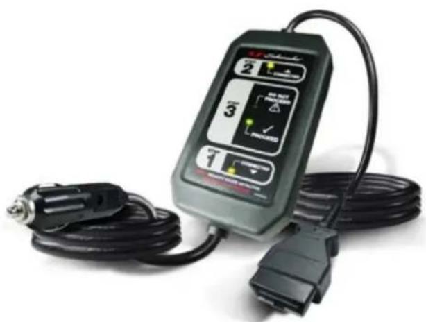
OBDL
natural_image
Electric shock absorber device with attached cable and connector (no visible text or symbols)INDEX
- ENGLISH ....3
- DEUTSCH....6
- ESPANOL....9
- FRANÇAIS ....12
- ITALIANO....15
PLEASE SAVE THIS OWNER'S MANUAL AND READ BEFORE EACH USE.
This manual will explain how to use the Memory Saver OBD-L safely and effectively. Please read and follow these instructions and precautions carefully.
IMPORTANT SAFETY INSTRUCTIONS – SAVE THESE INSTRUCTIONS
This manual will show you how to use your memory saver detector safely and effectively. Please read, understand and follow these instructions and precautions carefully, as this manual contains important safety and operating instructions.
WORKING IN THE VICINITY OF A LEAD-ACID BATTERY IS DANGEROUS. BATTERIES GENERATE EXPLOSIVE GASES DURING NORMAL OPERATION. IT IS IMPORTANT THAT YOU FOLLOW THESE INSTRUCTIONS EACH TIME YOU USE THE OBD-L 12V OBD.
WARNING: Pursuant to California Proposition 65, this product contains chemicals known to the State of California to cause cancer and birth defects or other reproductive harm. Wash hands after handling.
- Read the entire manual before using this product. Failure to do so could result in serious injury.
- Use the memory saver detector in a well-ventilated area.
- This memory saver detector is not intended for use by children.
- Do not expose the memory saver detector to rain or snow.
- Do not operate the memory saver detector if it has received a sharp blow, been dropped or otherwise damaged in any way; take it to a qualified service person.
- Inspect the battery for a cracked or broken case or cover. If the battery is damaged, do not use the memory saver detector.
- Do not disassemble the memory saver detector; take it to a qualified service person when service or repair is required. Incorrect reassembly may result in a risk of fire or electric shock.
- Follow these instructions and those published by the battery manufacturer and the manufacturer of any equipment you intend to use in the vicinity of the battery. Review the cautionary markings on these products and on the engine.
PERSONAL SAFETY PRECAUTIONS
- Wear complete eye protection and protective clothing when working near lead-acid batteries. Always have someone nearby for help.
- Have plenty of fresh water, soap and baking soda nearby for use, in case battery acid contacts your eyes, skin, or clothing. Wash immediately with soap and water and seek medical attention.
- If battery acid comes in contact with eyes, flush eyes immediately for a minimum 10 minutes and get medical attention.
- Neutralize any acid spills thoroughly with baking soda before attempting to clean up.
- Remove all personal metal items from your body, such as rings, bracelets, necklaces and watches. A battery can produce a short circuit current high enough to weld a ring to metal, causing a severe burn.
- Never smoke or allow a spark or flame in the vicinity of the battery or engine.
USING THE MEMORY SAVER DETECTOR
Use the memory saver detector cable to save the vehicle's on-board diagnostic computer settings (radio programs, diagnostic codes, etc.) while the battery is disconnected from the vehicle during repair or maintenance.
NOTE: Some vehicle manufacturers do not allow the use of a memory saver through the OBDII. Consult the vehicle manufacturer before use, to determine if a memory saver is acceptable for use on the vehicle.
- Make sure that the power source used is greater than or equal to 12VDC. If using a portable battery device, make sure it is fully charged.
- Turn off the vehicle, remove the key, and make sure all accessories are off.
WARNING: Verify all vehicle accessories are OFF (fan, interior lights, etc.). Headlights must be in OFF position, not AUTO position. To prevent overloading of a vehicle fuse, OBD-L fuse or other vehicle damage, do not use the memory saver through the OBDII port if the vehicle's current draw is 4 amps or more when the vehicle is in a KEY OFF condition (use an amp clamp to measure the amperage draw). If unable to measure the vehicle's current draw, turn the vehicle's key to the
OFF position and wait 25 minutes. This ensures that all retained accessories are in a power OFF state (for example: fan, headlights, etc.).
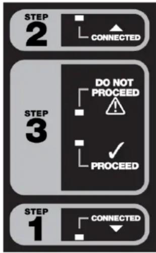
- Connect the 12V power plug of the OBD-L to your 12V DC power supply. Make sure plug is firmly in place. The yellow CONNECTED LED in box #1 will light, indicating a good connection.
WARNING: Do not connect the 12V power plug of the OBD-L into the power outlet within the same vehicle from which you are removing the battery.
-
Connect the OBD-L 12V OBD diagnostic connector to the vehicle's OBD plug. Make sure the connector is fully engaged. The yellow CONNECTED LED in box #2 will light, indicating a good connection.
-
Verify that the green PROCEED LED in box #3 is lit, indicating you may disconnect the vehicle's battery. If the red DO NOT PROCEED LED in box #3 lights, do not disconnect the vehicle's battery; disconnect the OBD-L and check the internal fuse or contact qualified service personnel for electrical system repair.
-
Disconnect the vehicle's battery cables and cover the positive and negative cables with an insulator, such as electrical tape. This prevents the connectors from touching metal, each other, or the chassis and causing a short circuit, due to the vehicle's electrical system receiving power through the OBD connection.
flowchart
graph TD
    A["STEP 1"] --> B["CONNECTED"]
    C["STEP 2"] --> D["CONNECTED"]
    E["STEP 3"] --> F["DO NOT PROCEED"]
    G["STEP 3"] --> H["PROCEED"]
WARNING: When working with the vehicle's battery, review all of the battery manufacturer's safety instructions, warnings and directives regarding battery disconnection, removal and replacement.
-
Remove the old battery and put the new battery into position.
-
Remove the insulator from the positive cable and connect it to the positive terminal of the new battery.
-
Remove the insulator from the negative cable and connect it to the negative terminal of the new battery.
-
Once the new battery is connected, unplug the memory saver's OBD connector from the vehicle's OBD plug and disconnect the 12V DC plug from the 12V power supply.
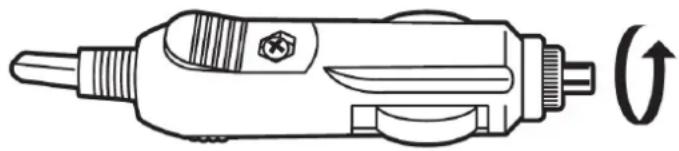
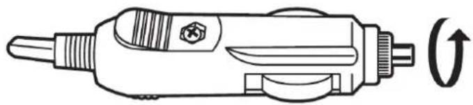
FUSE REPLACEMENT
The 12V power plug adaptor operates with a supplied 5A 250V glass fuse.
- Access the fuse compartment by turning the tip of the adaptor in a counterclockwise direction.
natural_image
Line drawing of a soldering iron with a curved arrow indicating rotation (no text or symbols)NOTE: The fuse is spring-loaded and caution must be taken to ensure that the spring does not "fly out" of the end of the fuse compartment when it is opened.
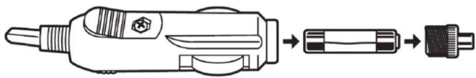
- Remove the fuse and replace it with one of the same type and rating.
natural_image
Line drawing of a soldering iron with three stages: wire end, internal pin, and external connector (no text or symbols)- Close the adaptor by turning the tip in a clockwise direction.
TROUBLESHOOTING
| PROBLEM | SOLUTION |
| The yellow CONNECTED LED in box #1 does not come on. | Make sure that the OBD-L’s 12V accessory power plug is fully engaged with the power source connector socket.Check the fuse. |
| The yellow CONNECTED LED in box #2 does not come on. | Make sure that the OBD-L’s diagnostics connector is fully engaged with the vehicle’s OBDII socket.Check the fuse. |
| The red DO NOT PROCEED LED in box #3 does not come on. | Indicates that the vehicle, by design, may not allow the use of the OBD-L.Check the fuse. |
flowchart
graph TD
    A["STEP 1"] --> B["CONNECTED"]
    C["STEP 2"] --> D["CONNECTED"]
    E["STEP 3"] --> F["DO NOT PROCEED"]
    G["STEP 3"] --> H["PROCEED"]
natural_image
Line drawing of a soldering iron with a curved arrow indicating rotation (no text or symbols)natural_image
Line drawing of a soldering iron with three stages: wire end, internal socket, and connector (no text or symbols)flowchart
graph TD
    A["STEP 1"] --> B["CONNECTED"]
    C["STEP 2"] --> D["CONNECTED"]
    E["STEP 3"] --> F["DO NOT PROCEED"]
    G["STEP 3"] --> H["PROCEED"]
natural_image
Line drawing of a soldering iron with a curved arrow indicating rotation (no text or symbols)natural_image
Line drawing of a soldering iron with three stages: tip, middle, and end (no text or symbols)flowchart
graph TD
    A["STEP 1"] --> B["CONNECTED"]
    C["STEP 2"] --> D["CONNECTED"]
    E["STEP 3"] --> F["DO NOT PROCEED"]
    G["STEP 3"] --> H["PROCEED"]
natural_image
Line drawing of a soldering iron with a curved arrow indicating direction (no text or symbols)natural_image
Line drawing of a soldering iron with three stages: disassembly, internal threading, and final assembly (no text or symbols)flowchart
graph TD
    A["STEP 1"] --> B["CONNECTED"]
    C["STEP 2"] --> D["CONNECTED"]
    E["STEP 3"] --> F["DO NOT PROCEED"]
    G["STEP 3"] --> H["PROCEED"]