
CHF1000 - Projector EPSON - Free user manual and instructions
Find the device manual for free CHF1000 EPSON in PDF.
| Product Type | Video Projector Mount |
| Brand | Epson |
| Model | CHF1000 |
| Maximum Load Capacity | 22.68 kg (50 lb) |
| Material | Steel |
| Mounting Options | Ceiling, wall (wood), concrete, threaded rod |
| Adjustments | Tilt, swivel, roll |
| Included Components | Projector mount (A), ceiling tube (B), mounting plate (D), security screws (F, G) |
| Power Supply | No electrical supply required |
| Maintenance | Periodically check screw tightness and installation stability |
| Safety Instructions | Do not exceed maximum load; ensure structure supports 5 times the weight |
| Repairability | Spare parts available: mount, tube, fixing screws |
| Warranty | Consult manufacturer warranty |
Frequently Asked Questions - CHF1000 EPSON
User questions about CHF1000 EPSON
0 question about this device. Answer the ones you know or ask your own.
Ask a new question about this device
Download the instructions for your Projector in PDF format for free! Find your manual CHF1000 - EPSON and take your electronic device back in hand. On this page are published all the documents necessary for the use of your device. CHF1000 by EPSON.
USER MANUAL CHF1000 EPSON
INSTALLATION INSTRUCTIONS
natural_image
Technical line drawing of a mechanical device with internal components and mounting holes (no text or symbols)Cinema Projector Mount
DISCLAIMER
Milestone AV Technologies and its affiliated corporations and subsidiaries (collectively "Milestone"), intend to make this manual accurate and complete. However, Milestone makes no claim that the information contained herein covers all details, conditions or variations, nor does it provide for every possible contingency in connection with the installation or use of this product. The information contained in this document is subject to change without notice or obligation of any kind. Milestone makes no representation of warranty, expressed or implied, regarding the information contained herein. Milestone assumes no responsibility for accuracy, completeness or sufficiency of the information contained in this document.
Chief® is a registered trademark of Milestone AV Technologies. All rights reserved.

IMPORTANT WARNINGS AND TIONS!

WARNING: A WARNING alerts you to the possibility of serious injury or death if you do not follow the instructions.

CAUTION: A CAUTION alerts you to the possibility of damage or destruction of equipment if you do not follow the corresponding instructions.

WARNING: Failure to read, thoroughly understand, and follow all instructions can result in serious personal injury, damage to equipment, or voiding of factory warranty! It is the installer's responsibility to make sure all components are properly assembled and installed using the instructions provided.

WARNING: Failure to provide adequate structural strength for this component can result in serious personal injury or damage to equipment! It is the installer's responsibility to make sure the structure to which this component is attached can support five times the combined weight of all equipment. Reinforce the structure as required before installing the component.

WARNING: Exceeding the weight capacity can result in serious personal injury or damage to equipment! It is the installer's responsibility to make sure the combined weight of all components attached to the CHF1000/2500 does not exceed 50 lbs (22.68 kg).

IMPORTANTS AVERTISSEMENTS et PRÉCAUTIONS!
![[165] 6.50 [43] [21] .84 [57] 2.25 [114] 4.50 [140] 5.50 [70] 2.75 [140] 5.50 [43] 1.69 [21] .84 1.50° DIA NPT](/content/2026/04/631658/images/803d85c39f9daad4cc14e87b492ec5c92ed925eaf336ed0845d11c02dbe8b6ed.jpg)

natural_image
Technical line drawing of a mechanical housing component (no text or symbols)
![[22] .88 [69] 2.72 [136] 5.36 ROLL ADJUSTMENT POINT ±3°](/content/2026/04/631658/images/066afbeb48226afb9a5e1d783c4135ebf0c88a6faef75d0147068dcc0a45ca17.jpg)
![[7] .28 [117] 4.61 PITCH ADJUSTMENT POINT +20°](/content/2026/04/631658/images/80d9db33ad9605aabee88401cb118cca500527af4187d36c636b54f4b7e05ff5.jpg)
DIMENSIONS: [MILLIMETERS] INCHES
LEGEND
 | Tighten Fastener |
| Serrez les fixations | |
| Serrare il fissaggio | |
| Befestigungsteil festziehen | |
| Apretar elemento de fijación | |
| Bevestiging vastdraaien | |
| Apertar fixador | |
 | Loosen Fastener |
| Desserrez les fixations | |
| Allentare il fissaggio | |
| Befestigungsteil lösen | |
| Aflojar elemento de fijación | |
| Bevestiging losdraaien | |
| Desapertar fixador | |
 | Phillips Screwdriver |
| Tournevis à pointe cruciforme | |
| Cacciavite a stella | |
| Kreuzschlitzschraubendreher | |
| Destornillador Phillips | |
| Kruiskopschroevendraaier | |
| Chave de fendas Phillips | |
 | Hex-Head Wrench |
| Clé à tête hexagonale | |
| Chiave esagonale | |
| Sechskantschlüssel | |
| Llave de cabeza hexagonal | |
| Zeskantsleutel | |
| Chave de cabeça sextavada |


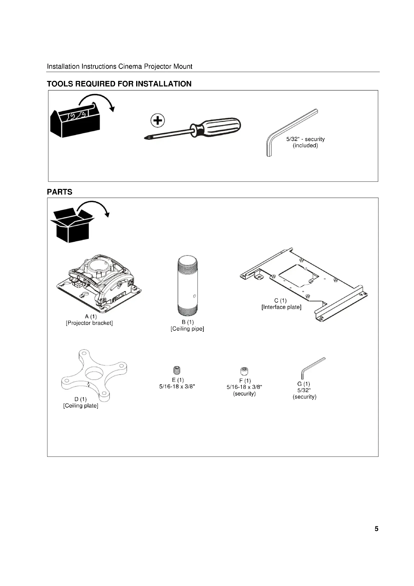
TOOLS REQUIRED FOR INSTALLATION

PARTS

natural_image
Simple black-and-white icon of an open box with a curved arrow indicating rotation or delivery (no text or symbols)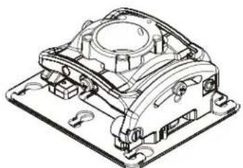
natural_image
Technical line drawing of a mechanical housing component (no text or symbols)A (1)
[Projector bracket]

B (1)
[Ceiling pipe]
![C (1) [Interface plate]](/content/2026/04/631658/images/47cdf767bbc1579b5418e1d7fc37ef4a8a6b1aa70219a40f8702dc0ee4bba72c.jpg)

natural_image
Isometric line drawing of a four-pronged mechanical part with a central hole and mounting holes (no text or symbols)[Ceiling plate]

E (1)
5/16-18×3/8"

F(1)
5/16-18×3/8"
(security)
G (1)
5/32"
(security)
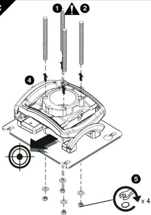
1 | CEILING INSTALLATIONNOTE: Projector mount can be mounted flush against the ceiling without using the ceiling pipe. See Sections 1a, 1b and 1c for flush mounting options. Additional hardware may be required.Threaded Pipe Installation1. Carefully determine required mounting location.IMPORTANT ! : This will require knowing the lens to screen distance. See projector specifications for details on determining this distance.2. Securely install ceiling plate (D) to ceiling joists.See drawing on the left for bolthole spacing.NOTE: If using only two holes for mounting, you must use opposing holes. |
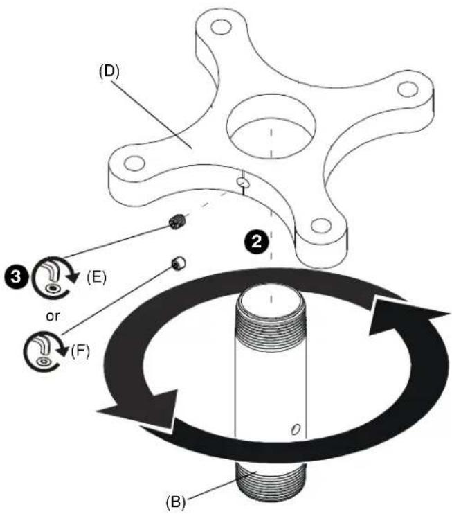 | Thread Ceiling Pipe into Ceiling Plate1. Align ceiling pipe (B) with installed ceiling plate (D).2. Turn ceiling pipe (B) counter-clockwise to thread onto ceiling plate (D) until hand-tight.3. Install 5/16-18 x 3/8" set screw (E) or 5/16-18 x 3/8" security set screw (F) into ceiling plate to secure pipe to plate. |
1 | Projector Mount Installation to Ceiling PipeWARNING: IMPROPER INSTALLATION CAN RESULT IN SERIOUS PERSONAL INJURY OR DAMAGE TO EQUIPMENT! Structural membersMUSTbe capable of supporting five times the combined weight of all equipment being mounted.1. Align projector mount (A) with end of ceiling pipe (B).2. Thread projector mount (A) up onto pipe by turning counter-clockwise until hand tight. |
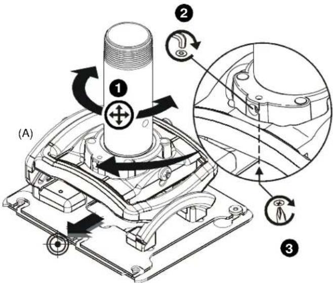 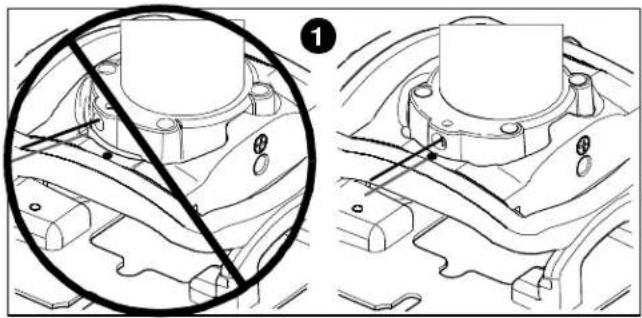 | Rough Alignment of Projector Mount1. Turn projector mount (A) clockwise or counter-clockwise until front of mount is facing target.IMPORTANT ! : When projector mount is properly positioned, the set screw access hole should be pointing directly at target.(see bottom detail in figure at left)2. Secure projector mount (A) to pipe by turning set screw until tight.CAUTION: DO NOT OVERTIGHTEN!Overtightening of setscrew can damage threads on pipe.3. Turn security screw using a Phillips screwdriver until set screw cannot be seen through access hole in projector mount. |
 | Wood Stud Installation1. Carefully determine required mounting location.IMPORTANT !: This will require knowing the lens to screen distance. See projector specifications for details on determining this distance.WARNING: IMPROPER INSTALLATION CAN RESULT IN SERIOUS PERSONAL INJURY OR DAMAGE TO EQUIPMENT! Structural membersMUST be capable of supporting five times the combined weight of all equipment being mounted.2. Using the projector bracket (A) as a guide, mark four mounting hole locations with a pencil or similar tool.3. Drill four 1/8" (3mm) dia. pilot holes to a depth of 1-3/4" (45mm) deep. |
  | 4. Align four mounting holes in projector bracket (A) with four pilot holes.IMPORTANT !: Make sure mount is properly oriented towards target before securing to structure.5. Secure projector bracket (A) to structure using four 1/4" flat washers and four 1/4" x 3" lag bolts (not included). |
1a

Concrete Installation
- Determine mounting location.

WARNING: IMPROPER INSTALLATION CAN RESULT IN SERIOUS PERSONAL INJURY OR DAMAGE TO EQUIPMENT! Structural members MUST be capable of supporting five times the combined weight of all equipment being mounted.
-
Using the projector bracket (A) as a guide, mark four mounting hole locations on ceiling using a pencil or similar tool.
-
Drill four 3/8" (10mm) dia. pilot holes to a depth of 2-1/2" (64mm) deep.

- Align four mounting holes in projector bracket (A) with four pilot holes.
IMPORTANT ! : Make sure mount is properly oriented towards target before securing to structure.
-
Install four Toggler A10 Alligator concrete anchors (not included) by inserting into pilot holes and pounding in until flush with mounting surface.
-
Secure projector bracket (A) to structure using four 1/4" flat washers and four 1/4" x 3" lag bolts. (not included)
1c
Threaded Rod Installation
The projector bracket (A) can be secured to unistrut, angle or channel assembly overhead structural members (trusses or I-beams) using four 1/4" diameter threaded rods.

WARNING: IMPROPER INSTALLATION CAN RESULT IN SERIOUS PERSONAL INJURY OR DAMAGE TO EQUIPMENT! Structural members MUST be capable of supporting five times the combined weight of all equipment being mounted.
- Carefully determine required mount position.
IMPORTANT !: This will require knowing the lens to screen distance. See projector specifications for determining this distance.
NOTE: Threaded rod and installation hardware not included.
-
Secure one end of the threaded rod to the structural member.
-
Install four 1/4-20 jam nuts on each threaded rod.
-
Install the projector bracket (A) on the threaded rod.
NOTE: Hole in the projector bracket (A) allows socket wrench access without unit disassembly.
- Secure the projector bracket to the threaded rod using four 1/4-20 nuts.

PROJECTOR INSTALLATION Install Interface Bracket to Projector

WARNING: IMPROPER INSTALLATION CAN LEAD TO PROJECTOR FALLING RESULTING IN SERIOUS PERSONAL INJURY OR DAMAGE TO EQUIPMENT. DO NOT substitute hardware. Use only the hardware provided by the manufacturer.
-
Line up mounting holes on projector with interface bracket (C) hole pattern.
-
Secure interface bracket (C) to projector using installation instructions and hardware provided with projector.
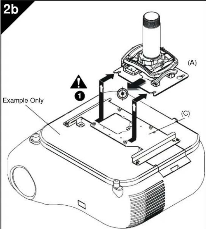
Install Projector With Interface Bracket to Projector Mount
- Orient projector with interface bracket as shown in Figure 3b at left.
- Lift projector so that screws are aligned with mounting slots in mount base.
- Slide projector with mounting bracket onto mounting slots in mount base until screws are seated against the back of mounting slots.

WARNING: IMPROPER INSTALLATION CAN LEAD TO PROJECTOR FALLING RESULTING IN SERIOUS PERSONAL INJURY OR DAMAGE TO EQUIPMENT. Make certain mounting slots in mount base slide under screws and that screws are seated in the back of slots.
2c

natural_image
Technical line drawing of a mechanical device with internal components and a magnified inset showing internal structure (no text or symbols)Securing Projector with Interface Bracket to Model RPM Mount.

WARNING: IMPROPER INSTALLATION CAN LEAD TO PROJECTOR FALLING RESULTING IN SERIOUS PERSONAL INJURY OR DAMAGE TO EQUIPMENT. Make certain mounting slots in mount base slide under thumb screws and that screws are seated in the back of slots.
- Move locking lever into the locked position in order to secure projector to projector mount.
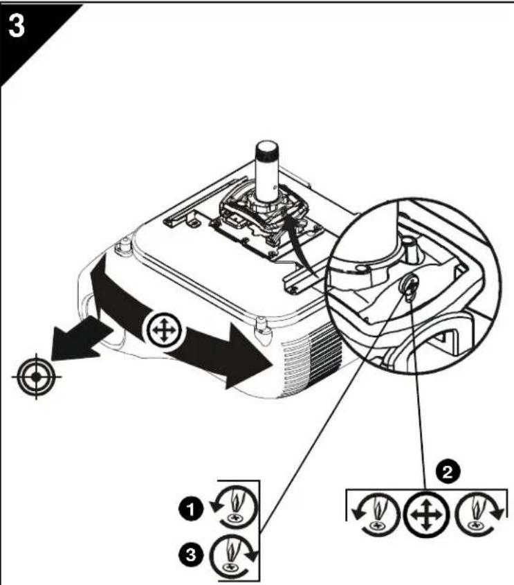
ADJUSTMENTS
YAW Adjustment
- Loosen YAW adjustment locking screw using a #2 Phillips screwdriver.
- Turn YAW micro-adjustment screw right or left using a #2 Phillips screwdriver until image is properly aligned on target.
- Tighten YAW adjustment locking screw using a #2 Phillips screwdriver.

Pitch Adjustment
- Loosen PITCH adjustment locking screw using a #2 Phillips screwdriver.
- Turn PITCH micro-adjustment screw right or left using a #2 Phillips screwdriver until image is properly aligned on target.
- Tighten PITCH adjustment locking screw using a #2 Phillips screwdriver.

Roll Adjustment
- Loosen ROLL adjustment locking screw using a #2 Phillips screwdriver.
- Turn ROLL micro-adjustment screw right or left using a #2 Phillips screwdriver until image is properly aligned on target.
- Tighten ROLL adjustment locking screw using a #2 Phillips screwdriver.
OUTILS REQUIS POUR L'INSTALLATION

PIÈCES

natural_image
Simple black-and-white icon of an open box with a curved arrow indicating rotation or delivery (no text or symbols)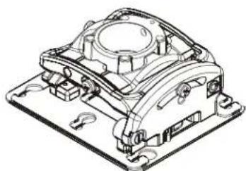
natural_image
Technical line drawing of a mechanical housing component (no text or symbols)natural_image
Isometric line drawing of a four-petal mechanical part with a central hole and mounting holes (no text or symbols)[Plaque du plafond]

E (1)
5/16-18 × 3/8 po
AJUSTEMENTS
natural_image
Simple black-and-white icon of an open box with a curved arrow indicating rotation or delivery (no text or symbols)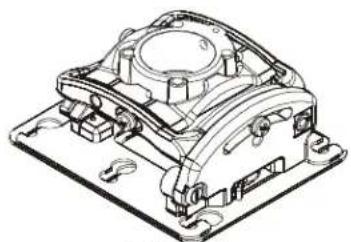
natural_image
Technical line drawing of a mechanical housing component (no text or symbols)natural_image
Isometric line drawing of a four-petal mechanical part with a central hole and mounting holes (no text or symbols)natural_image
Simple black-and-white icon of an open box with a curved arrow indicating rotation or delivery (no text or symbols)
natural_image
Technical line drawing of a mechanical housing component (no text or symbols)natural_image
Technical line drawing of a four-pronged mechanical part with a central hole and mounting holes (no text or symbols)[Placa do teto]

E (1)
5/16-18×3/8"

Cinema Projector Mount
Installation Instructions


- INSTALLATION INSTRUCTIONS
- Cinema Projector Mount
- DISCLAIMER
- IMPORTANT WARNINGS AND TIONS!
- IMPORTANTS AVERTISSEMENTS et PRÉCAUTIONS!
- TOOLS REQUIRED FOR INSTALLATION
- PARTS
- Concrete Installation
- 1c
- Threaded Rod Installation
- PROJECTOR INSTALLATION Install Interface Bracket to Projector
- Install Projector With Interface Bracket to Projector Mount
- 2c
- Securing Projector with Interface Bracket to Model RPM Mount.
- ADJUSTMENTS
- YAW Adjustment
- Pitch Adjustment
- Roll Adjustment
- OUTILS REQUIS POUR L'INSTALLATION
- PIÈCES
- AJUSTEMENTS
Brand : EPSON
Model : CHF1000
Category : Projector