
FACT12CAPS - Air Conditioning Furrion - Free user manual and instructions
Find the device manual for free FACT12CAPS Furrion in PDF.
| Product Type | Roof air conditioner for recreational vehicle |
| Brand | Furrion |
| Model | FACT12CAPS |
| Cooling Capacity | 12,000 BTU/h (estimated) |
| Refrigerant | R410A |
| Power Supply | 115 V~, 60 Hz, 1 phase |
| Power Consumption (cooling) | Approximately 1283 W (based on similar models) |
| Rated Current | Approximately 11.3 A |
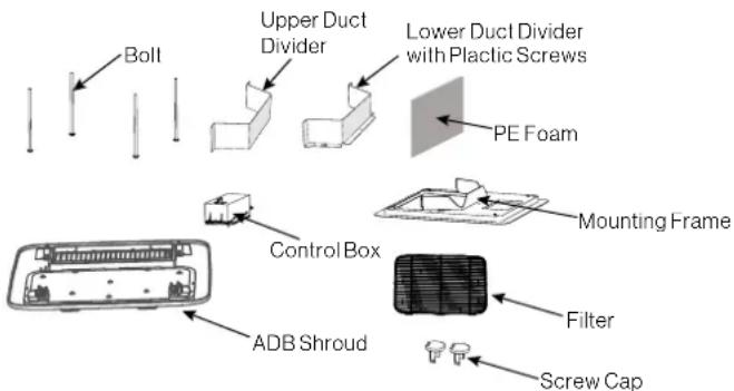
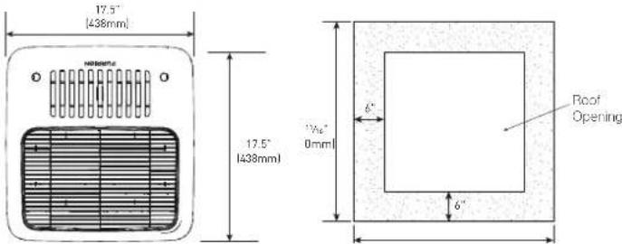
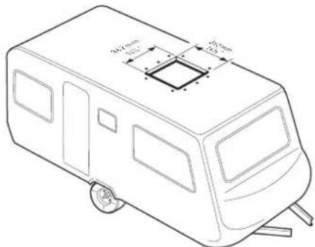
| Roof Unit Dimensions (L x W x H) | 34 ½ x 27 ½ x 13 ½ inches (876 x 699 x 343 mm) |
| Roof Unit Weight | Approximately 45 kg (100 lb) |
| Required Roof Opening | 14 ¼ x 14 ¼ inches (362 x 362 mm) |
| Compatible Roof Thickness | 3.5 to 6 inches (89 to 152 mm) |
| Main Functions | Cooling, heating (depending on configuration), ventilation, dehumidification |
| Control Type | Digital wall thermostat (sold separately) |
| Air Distribution System | With or without duct (4 to 8 registers per unit) |
| Air Filter | Washable, clean every 4 weeks |
| Filter Maintenance | Clean with warm soapy water, replace every 12 months |
| Freeze Protection | Built-in frost sensor |
| Installation | By a qualified professional; comply with NFPA 1192, NFPA 70 (USA) |
| Safety | Grounding mandatory; disconnect before servicing |
| Warranty | See provided warranty manual |
Frequently Asked Questions - FACT12CAPS Furrion
User questions about FACT12CAPS Furrion
0 question about this device. Answer the ones you know or ask your own.
Ask a new question about this device
Download the instructions for your Air Conditioning in PDF format for free! Find your manual FACT12CAPS - Furrion and take your electronic device back in hand. On this page are published all the documents necessary for the use of your device. FACT12CAPS by Furrion.
USER MANUAL FACT12CAPS Furrion
natural_image
Black Furrion air conditioner unit with ventilation grille and side panel (no visible text or symbols)| Furrion Model No. Lippert No. | |
| FACR13HESA-PS 2021132276 | |
| FACR13HESA-BL 2021130013 | |
| FACR13HESA-PS-AM 2021132277 | |
| FACR13HESA-BL-AM 2021132275 | |
| FACR14SA-PS 2021123613 | |
| FACR14SA-BL 2021123563 | |
| FACR14SA-PS-AM 2021123705 | |
| FACR14SA-BL-AM 2021123707 | |
| FACR15SA-PS 2021123799 | |
| Furrion Model No. Lippert No. | |
| FACR15SA-BL 2021123630 | |
| FACR15SA-PS-AM 2021123793 | |
| FACR15SA-BL-AM 2021123708 | |
| FACR15HESA-PS 2021130009 | |
| FACR15HESA-BL 2021130010 | |
| FACR15HESA-PS-AM 2021130011 | |
| FACR15HESA-BL-AM 2021130008 | |
| FACT12CA-PS 2021123541 | |
| FACT12CA-PS-OEM 2022007391 | |
Thank you for purchasing this Furrion® product. Before operating your new appliance, please read these instructions carefully. This instruction manual contains information for safe use, installation and maintenance of the appliance.
Please keep this instruction manual in a safe place for future reference. This will ensure safe use and reduce the risk of injury. Be sure to pass on this manual to new owners of this appliance.
The manufacturer does not accept responsibility for any damages due to disregarding these instructions.
CONTENTS
EXPLANATION OF SYMBOLS....2
IMPORTANT SAFETY INSTRUCTIONS....2
Handling the device....2
Handling Electrical Cables....3
BEFORE INSTALLING 3
What's in the Box....3
Choosing Proper Location for the Air Conditioner 3
Roof Preparation 4
Air Distribution Duct Sizing and Design 5
Air Distribution System Installation....5
Preparing Wire Connections....5
INSTALLATION....6
Installing the Rooftop Unit....6
Installing the Wall Thermostat 6
Installing the Air Distribution Box....6
DIP Switch Settings 8
Wire Connection - Digital Furrion Wall Controller/Thermostat....9
Final Installation....10
OPERATION 11
Ducted Systems....11
Non-Ducted System 11
Thermostat Use 11
CLEANING AND MAINTENANCE 12
TROUBLESHOOTING 12
SPECIFICATIONS....13
WIRING DIAGRAM....13
EXPLANATION OF SYMBOLS
This manual has safety information and instructions to help you eliminate or reduce the risk of accidents and injuries. Always respect all safety warnings identified with these symbols. A signal word will identify safety messages and property damage messages, and will indicate the degree or level of hazard seriousness.
DANGER
Indicates an imminently hazardous situation which, if not avoided, will result in death or serious injury.
WARNING
Indicates a potentially hazardous situation which, if not avoided, could result in death or serious injury.
CAUTION
Indicates a potentially hazardous situation which, if not avoided, may result in minor or moderate personal injury, or property damage.
IMPORTANT SAFETY INSTRUCTIONS
This manual has safety information and instructions to help users eliminate or reduce the risk of accidents and injuries. Please read this instruction manual carefully before installation and start-up, and store it in a safe place for future reference. If you pass on the device to another person, hand over this instruction manual along with it.
The manufacturer accepts no liability for damage in the following cases:
• Faulty assembly or connection
- Damage to the product resulting from mechanical influences and excess voltage
- Alterations to the product without express permission from the manufacturer
- Use for purposes other than those described in the operating manual.
The following basic safety information should be heeded when using electrical devices to protect against:
Electric shock
- Fire hazards
- Injury
All Furrion product referenced in this manual is to be installed in accordance with local and national codes, including the latest editions of the following standards:
USA:
-NFPA 1192
-NFPA 70
Canada:
C22.1
CSA Z240
Handling the device
WARNING
- Installation and repair of the rooftop air conditioner must only be carried out by qualified personnel who are familiar with the risks involved and the relevant regulations. Inadequate repairs may cause serious hazards.
- Electrical devices are not toys. Keep electrical devices out of reach of children or elderly persons. Do not allow them to use electrical devices without supervision.
- Prevent inexperienced people from using the device without supervision.
- Do not undo the upper cover of the rooftop air conditioner in the event of a fire. Use approved extinguishing agents instead. Do not use water to extinguish fires.
CAUTION
- The rooftop air conditioner must be installed securely so that it cannot fall down.
- Only operate the rooftop air conditioner if you are certain that the housing and the cables are not damaged.
- Do not use the rooftop air conditioner near flammable fluids or in closed rooms.
- Make sure no combustible objects are stored or installed near the air outlet. A distance of at least 20" must be kept.
- Do not reach into air outlets or insert any foreign objects into the device.
• Only use the device as intended.
- Do not make any alterations or conversions to the device.
- If faults occur in the refrigerant circuit, the system must be checked by a certified service technician and repaired properly. The refrigerant must never be released into the air.
Handling Electrical Cables
WARNING
The electrical power supply must only be connected by a qualified electrician.
CAUTION
- Refer to NEC (National Electric Code) for proper sizing of wire gauge (awg) based on cable length and overcurrent protection rating that is suppling power to the air conditioner.
- See rooftop unit nameplate for proper overcurrent protection sizing.
-
Attach and lay the cables so that they cannot be tripped over or damaged.
-
Only a qualified electrician should connect the rooftop air conditioner to electrical power.
- Do not lay loose or bent cables next to electrically conductive materials.
- Do not pull on the cables.
- Use cable ducts to lay cables through walls with sharp edges.
- Refer to rooftop unit nameplate and NEC for proper power supply rating.
BEFORE INSTALLING
Read this installation manual completely before installing the rooftop air conditioner.
The following tips and instructions must be observed while installing the rooftop air conditioner.
What's in the Box
Open and remove the components from carton. Make sure you have all the following items included in the packaging, if any item is missing, contact your dealer.
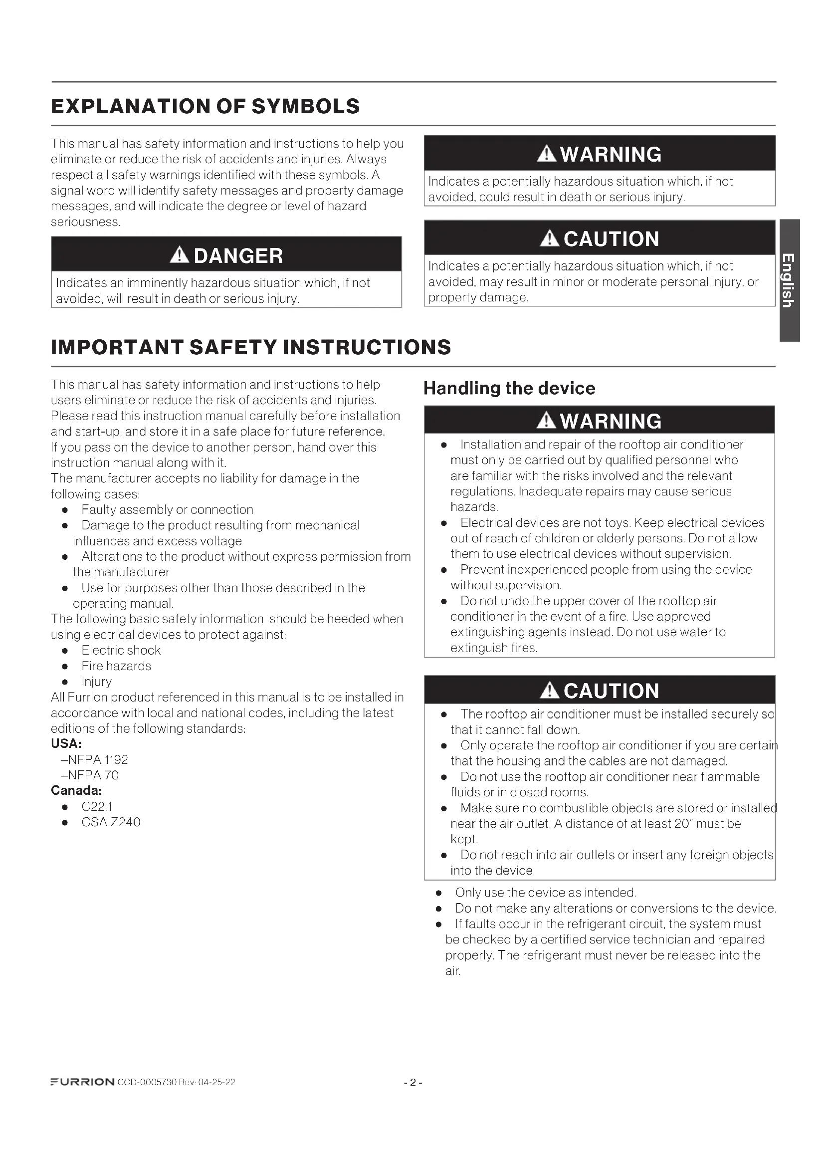
Rooftop Air Conditioner (sold separately):
- Rooftop Unit x 1
- Warranty Manual x 1
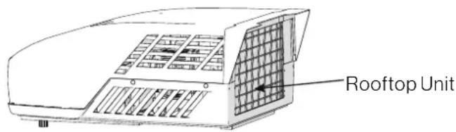
Air Distributor Box:
• Upper Duct Divider x 1
- Lower Duct Divider x 1
- Bolt x 4
- Mounting Frame x 1
• Control Box (sold separately) x 1
• Air Distribution Box (ADB) Shroud x 1
- Filter x 1
- PE Foam x 1
• Self-tapping Screws x 6
- Screw Cap x2
• Instruction Manual x 1
• Warranty Manual x 1
Choosing Proper Location for the Air Conditioner
IMPORTANT: The roof must be designed to support the weight of the rooftop unit and the weight of 2 installers standing on the roof.
There are two ways of installing the rooftop air conditioner:
- Using the existing roof vent opening in the vehicle roof.
- Making a new opening. In this case the opening should be reinforced by an appropriate frame as required.
Existing Roof Vent Opening
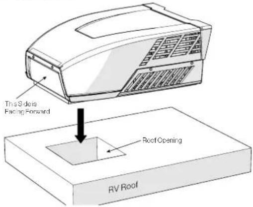
The air conditioner is designed to fit over an existing 14" roof vent opening.
New Opening
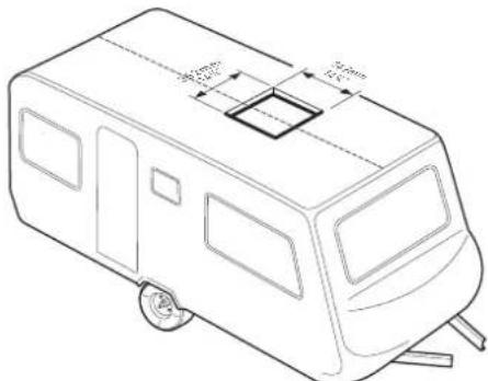
When no roof vent is available or another location is desired, the following is recommended:
-For one unit installation - the air conditioner should be mounted slightly forward of center (front to back) and centered from side to side.
-For two unit installations, install one air conditioner one third from the front of the RV and the other air conditioner two thirds from the front of the RV, aligned in the center.
It is preferred that the air conditioner be installed on a relatively flat and horizontal roof section measured when the RV is parked on a level surface.
NOTE: A 15^ slant to either side or front to back is acceptable for all units. If the roof exceeds 15^ please use an exterior leveling shim to make air conditioner level.
After the Location Has Been Selected:
- Check for obstructions in the area where the air conditioner will be installed.
- Check the inside of the RV for return air kit obstructions. (i.e. door openings, room dividers, curtains, ceiling fixtures, etc.) Allow 6" (152mm) space from the opening to account for any potential return air kit obstructions.
Roof Preparation
Opening Requirements - Before preparing the ceiling opening, decide on the type of system options. Read all of the following instructions before beginning the installation.
WARNING
Fire/Electric Shock Hazard
- Make sure there are no obstacles inside the RV roof, floor and walls, such as wires and pipes.
- Shut off the gas supply and disconnect the 115VAC power from the RV before drilling or cutting into the RV. Failure to obey these warnings could result in death or serious injury.
Roof Thickness
The installation of air conditioner suits for roof thickness from 3.5" (90mm) to 6" (152mm). For other thickness, please contact Furrion or Furrion authorized service agent.
Installing in an Existing Opening
- Unscrew and remove the roof vent.
- Remove all caulking compound around the opening.
- If the opening exceeds 1414 " x 1414 " (+½"), it will be necessary to resize the opening to 1414 " x 1414 " (+½"). If the opening is less than 1414 " x 1414 " (+½"), it must be enlarged.
Making a New Opening
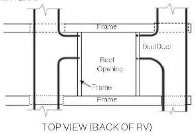
If a roof vent opening will not be used, a 1414 " x 1414 " ( +12 ") (362mm x 362mm) opening must be cut through the roof and ceiling of the RV. This opening must be located between the roof reinforcing members.
The 14¼" x 14½" (+½") opening is part of the return air system of the air conditioner and must be finished in accordance with NFPA Standard 501C Section 2.7.2.
- Mark a 1414 " x 1414 " (+½") square on the roof and carefully cut an opening.
- Using the roof opening as a guide, cut a matching hole in the ceiling.
NOTE: Maintain structural integrity. Otherwise damage to product and/or RV could occur. Always observe the following guidelines while structuring the opening.
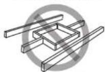
Do not cut roof structure or rafters
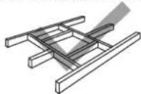
Good: rafters supported by cross beams
Good: location between roof rafters
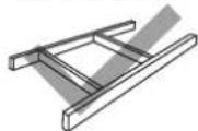
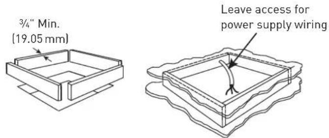
- The opening created must be framed to provide adequate support and prevent air from being drawn from the roof cavity.
- Lumber 34 " or more in thickness must be used. Remember to provide an entrance hole for power supplies, wall thermostat and furnace wiring for connections. Leave 15" (381mm) minimum at the front of the opening.
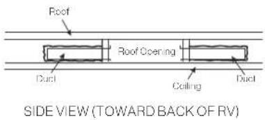
Air Distribution Duct Sizing and Design
The installer of this system must design the air distribution system for their particular application.
NOTE: Make sure ductwork will NOT bend or collapse during and after installation, and that it is correctly insulated and sealed. Otherwise, damage to roof structure and ceiling could occur.
The following requirements must be met for properly operate the unit:
| Roof Cavity Depth 3 | 5"-6" (89mm-152mm) | |
| Duct Cross Sectional Area | 21 Sq. In. Min. | |
| Duct Size | Depth | 1 12 " Min. - 2 12 " Max. (38mm Min. - 63.5mm Max.) |
| Width | 7" Min. - 10" Max. (178mm Min. - 254mm Max.) | |
| Total Duct Length | 15Ft. Min. - 40Ft. Max. (4.5m - 13m) | |
| Duct Length (short run) | 1/3 Total Duct Length | |
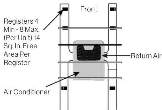
| Register Requirements per A/C Unit | Number Required 4 Min. | 8 Max. |
| Supply Register Free Air Area | 14 Sq. In. (90 sq. cm) | |
| Return Register Free Air Area | 40 Sq. In. (258 sq. cm) | |
| Distance From Duct End | 5" Min. - 8" Max. (127mm Min. - 203mm Max.) | |
| Distance From Elbow 15" | (381mm) | |
| Total System Static Air Pressure | Blower at High Speed, Filter & Grille In Place | 0.55 - 1.10 In. W.C. |
- Properly insulate and seal all discharge air ducts to prevent condensation from forming on their surfaces or adjacent surfaces during operation of the unit. This insulation must be R-7 minimum.
- Return air openings must have 80 square inches (516 square centimeters) minimum free area including the filter.
- Return air to the unit must be filtered to prevent dirt accumulation on the unit cooling surface.
Air Distribution System Installation
It is the responsibility of the installer to review each RV floor plan to determine the following items in conjunction with "Air Distribution Duct Sizing and Design" section
NOTE: Alternate configurations and methods may be used which will allow the unit to operate properly, however, these alternate configurations and methods MUST be approved by Furrion in writing.
- Duct size
- Duct layout
- Register size
- Register location
• Thermostat location - Indoor temperature sensor location (if applicable)
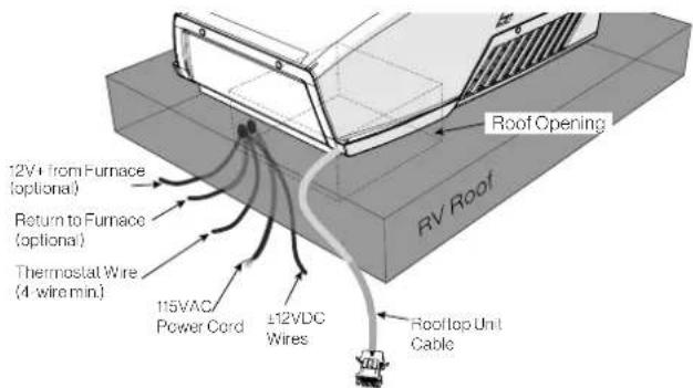
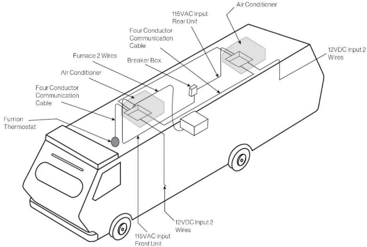
Preparing Wire Connections
Each rooftop air conditioner opening must be prepared with proper wiring to connect the ceiling controller of the air conditioner to the 115VAC and 12VDC supply voltage, wall thermostat and furnace switch.
NOTE: The wire connections need to be positioned in the forward facing 1/4 section of the opening.
DANGER
Electrical Shock Hazard
- Disconnect power before servicing. Failure to obey this warning could result in death or serious injury.
- Provide grounding in compliance with all applicable electrical codes. Failure to obey this warning could result in death or serious injury.
115VAC Supply
- Prepare a dedicated 20 amp rated circuit for each air conditioner unit, protected with a time delay fuse or circuit breaker.
NOTE: With multiple air conditioners on a 50 amp service, it is best to balance between the line voltage legs.
- Extend circuit with a 12AWG 2-wire with ground to the roof opening.
NOTE: The wire gauge is generally acceptable per NEC code, refer to rooftop unit nameplate and applicable code for proper sizing.
- Protect the wire where it passes through any rough
surfaces or openings.
- Terminate with at least 15" (381mm) of supply wire extending out of the roof opening. This ensures an easy connection at the control box.
12VDC Supply
- Prepare a 15 amp max protected circuit to supply power to all air conditioner units.
NOTE: The branch circuit can be dedicated or shared with other utilization equipment. - Extend circuit with a 14AWG 2-wire, (12V+, 12V-) to each roof opening.
- Protect the wire where it passes through any rough surfaces or openings.
- Terminate with at least 15" (381mm) of supply wire extending out of the roof opening. This ensures an easy connection at the control box.
INSTALLATION
Installing the Rooftop Unit
CAUTION
- The rooftop unit weighs approximately 100 pounds (45 kg). To prevent back injury, use a mechanical hoist when lifting or moving the unit. Failure to obey this warning could result in injury.
- Do not slide unit. It may damage the gasket at the bottom of the rooftop unit and cause leakage.
- Do not grasp the ventilation slots to lift the rooftop unit up.
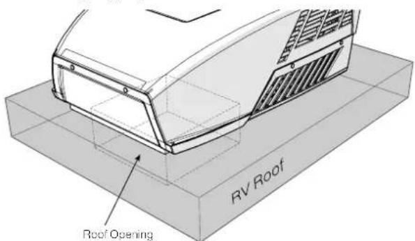
Hold the bottom of the unit, lift and position the rooftop unit into the prepared opening using the gasket at the bottom of the rooftop unit as a guide.
This completes the outside installation of the rooftop unit. Minor adjustments can be done from inside of the RV if required.
Wall Controller Connection (Single and Multizone Thermostat)
- Prepare 4 wires to connect between the ceiling controller (roof opening) and wall controller/thermostat (wall opening).
NOTE: 18AWG max should be used, Furrion recommends using a standard thermostat wire with at least 4-wires. - Terminate with at least 15" (381mm) of wire end for easy connection.
- For Multizone installations, prepare additional wiring of the same type to connect between each roof opening.
Furnace Switch (Optional)
- If required to operate the furnace using the air conditioner wall controller/ thermostat, prepare 2-wires in the roof opening to connect the desired ceiling control zone with the furnace's thermostat circuit.
NOTE: This serves as a 12V+ line, that becomes hot only when the ceiling controller closes the furnace switch to turn the furnace on.
- Terminate with at least 15" (381mm) of wire at each end for easy connection.
Installing the Wall Thermostat
Furrion provides 2 types of wall thermostats (sold separately) in different functionalities:
• Single zone wall thermostat
• Multi zone wall thermostat
Based on the wall thermostat version you selected. Please refer to the separate instruction manual on how to install the wall thermostat to the RV.
Installing the Air Distribution Box
NOTE: The installation of the air distribution box is same for both ducted and non-ducted structures.
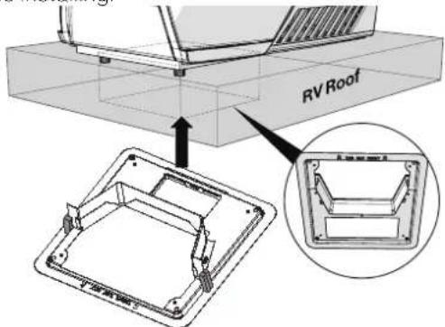
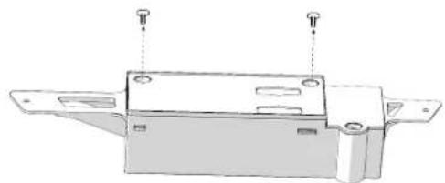
The rooftop unit is fixed on the RV roof using 4 long bolts through the mounting frame from the interior of the RV ceiling.
- Check the gasket alignment of the rooftop unit inside the RV over the roof opening and adjust as necessary by lifting and moving slightly.
- Reach up into the return air opening and pull down the rooftop unit electric cord. Ensure all terminated wire ends specified in "Preparing Wire Connections" section are accessible.
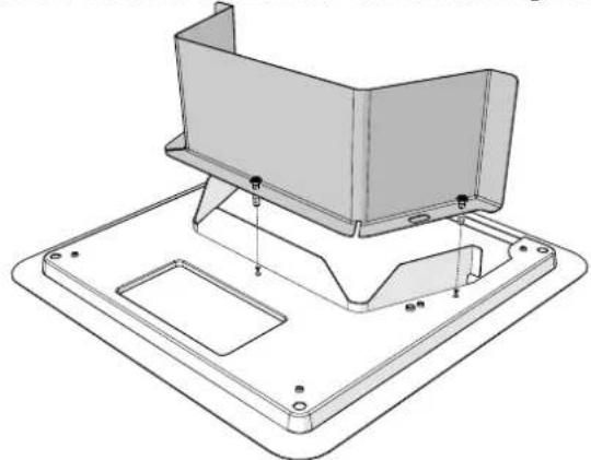
- Assemble the lower duct divider to the mounting frame.
natural_image
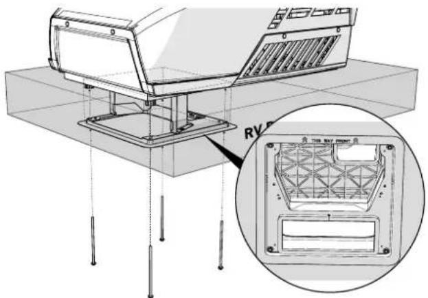
Technical line drawing of a mechanical assembly with mounting bracket and mounting base (no text or symbols)- Install the assembled mounting frame and the lower duct divider into the rooftop opening. Make sure the "THIS WAY FRONT" mark is facing front (the direction of the vehicle) while installing.
- Fix the assembled mounting frame and lower duct divider into the rooftop unit using 4 bolts provided. Evenly tighten the four bolts to a torque of 40 to 50 inch pounds. This will compress the roof gasket to approximately 12 ".
NOTE: If bolts are left loose there may not be an adequate roof seal or if over tightened, damage may occur to the rooftop base or mounting frame.
natural_image
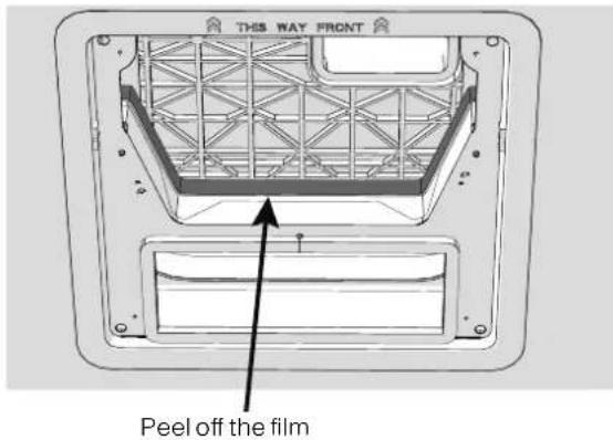
Technical line drawing of a mounted air conditioner unit with a close-up inset showing internal components (no text or symbols)- Remove the film off the double sided sticky tape found on the top inner side of the lower duct divider.
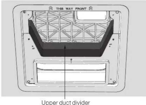
- Stick the upper duct divider into the assembled mounting frame.
NOTE: Make sure the upper duct divider is compressing the top foam on the base of the air conditioner unit, and compress tightly to the doubled sided tape on the lower duct divider to ensure a positive retention.
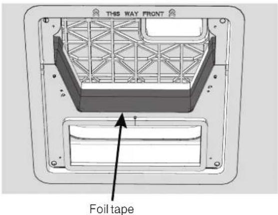
- Use self adhesive foil tape to seal the two halves of the duct divider together and any potential gaps around the duct divider to roof opening that may allow cold air to leak back into the warm intake side.
NOTE: Clean metal surfaces to remove any oils to ensure good adhesion of the foil tape.
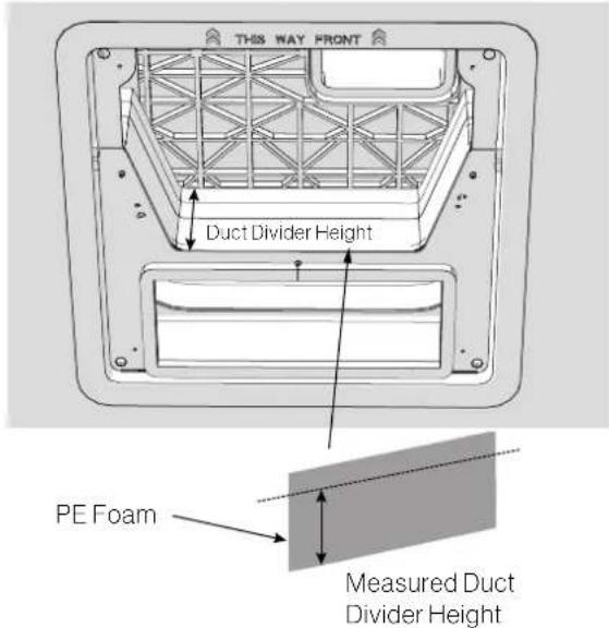
- Measure the height of the duct divider, and cut the PE foam with a utility knife to the measured dimension. Peel paper backer of foam to reveal sticky adhesive. Evenly adhere PE condensation foam to duct divider, working material into crevices and surfaces for a tight uniform fit across the duct divider surface.
DIP Switch Settings
The DIP switches enable/disable different communications between the ceiling controller and wall thermostat for functions such as, zone selection, furnace operation, and additional accessories.
The controls are preset with the following active DIP switch settings:
Single Zone: Furnace on (FACC12SA-BL)
Multi Zone: Zone 1; Furnace on (FACC12ZA-BL, FACC12NA-BL, FACC12ESZA, FACC12ZA, FACC12HE, FACC12ESHE
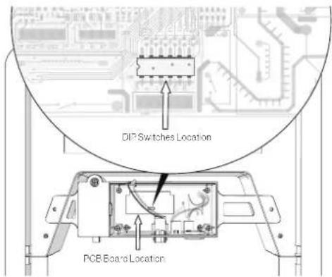
Location of the DIP Switch
The DIP switches are located on the PCB board of the control box. Each time you want to set the DIP, you should open the control box and find the DIP switches.
- Remove the cover of the control box, and find the PCB board.
natural_image
Technical line drawing of a mechanical component with mounting holes and a base plate (no text or symbols)- Locate the position of the DIP switches on the PCB board.
Setting DIP Switches
! DANGER
Electrical Shock Hazard
Disconnect power before servicing. Failure to obey this warning could result in death or serious injury.
- Remove power when setting dip switches, make sure all 115VAC and 12VDC power to the control board is removed.
- Use a small tool, slide the dip switch to either ON/OFF.
NOTE: If 12V+ is present when making a setting change, It will be is necessary to cycle power to reset the control to make the setting active.
Single Zone DIP Switches:
| Heat Pump (selected models) | DIP 3 Reserved | ||
| Furnace DIP 4 | OFF Furnace Off | ||
| ON Furnace On | |||
| Electric Heat (selected models) | DIP 5 | OFF Electric Heat Off | |
| ON Electric Heat On | |||
| Analog / Digital DIP 6 | OFF Digital | ||
| ON Analog | |||
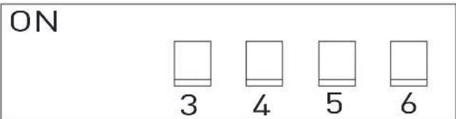
Multi Zone DIP Switches:
- Each zone requires an independent ceiling control box, but will share one wall thermostat control.
- It is important that each independent zone is set to a unique zone value (1-4) by setting the DIP 1 and DIP 2 to avoid repetition and communication conflicts with the wall thermostat control.
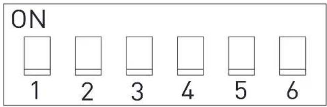
| Zone Selection* | DIP 1 DIP 2 | ZONE Setting | ||
| OFF OFF ZONE1 | ||||
| OFF ON ZONE2 | ||||
| ON OFF ZONE3 | ||||
| ON ON ZONE4 | ||||
| Heat Pump (selected models) | DIP 3 Reserved | |||
| Furnace DIP 4 | OFF Furnace Off | |||
| ON Furnace On | ||||
| Electric Heat (selected models) | DIP 5 | OFF | Electric Heat Off | |
| ON | Electric Heat On | |||
| Analog / Digital DIP 6 | OFF Digital | |||
| ON Analog | ||||
Wire Connection - Digital Furrion Wall Controller/Thermostat
DANGER
Electrical Shock Hazard
- Disconnect power before servicing.
- Provide grounding in compliance with all applicable electrical codes.
Failure to obey this warning could result in death or serious injury.
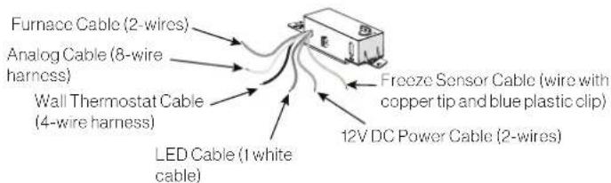
- Familiarize yourself with the ceiling controller and wire harnesses.
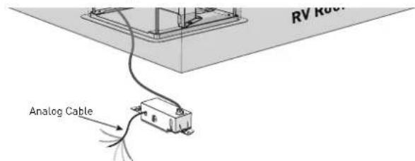
NOTE: When connecting to a Furrion wall controller/ thermostat, the analog harness bundle is not used and can be tucked away. The ends do not need to be capped or taped.
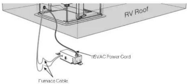
- Loosen the strain relief and compartment cover of the control box and pass the 115VAC power cord through the strain relief hole and re-tighten the cable clamp until properly restrained. Do not over tighten.
- Make wire connections following the below color codes. Black - Hot White - Neutral Green/yellow - Ground
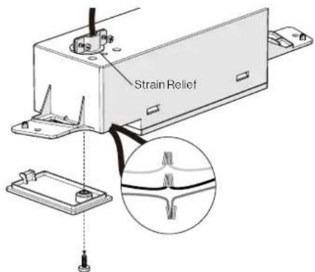
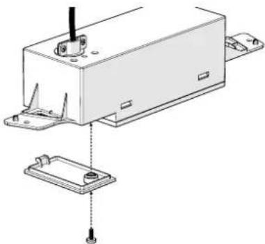
- Fit all cables into the cable compartment and tuck any excess wires up out of the way. Tighten the cover with screw.
natural_image
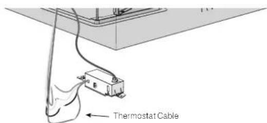
Technical line drawing of a mechanical assembly with mounting bracket and base plate (no text or symbols)- Locate the four thermostat cables of the control box (red, green, blue and purple), which are tied together and tagged with "To wall thermostat", and connect them to the thermostat wire that extends to the wall.
IMPORTANT: Note the function marked on the wire end and carefully trace and mark its function at the end of the wire extension so that proper connection can be made at the wall controller / thermostat.
Crossing the wires could prevent the control from operating properly, or even cause damage. If uncertain, perform a continuity test through each extension to confirm.
- If applicable, locate the furnace wires from the ceiling controller, which are two separate brown wires tagged with "FURN". Connect them with the 12V+ wire from the furnace, and the return wire to the furnace.
NOTE: Polarity does not matter, connection can be freely made to either wire. Do not connect the two brown "FURN" wires together.
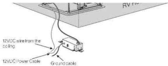
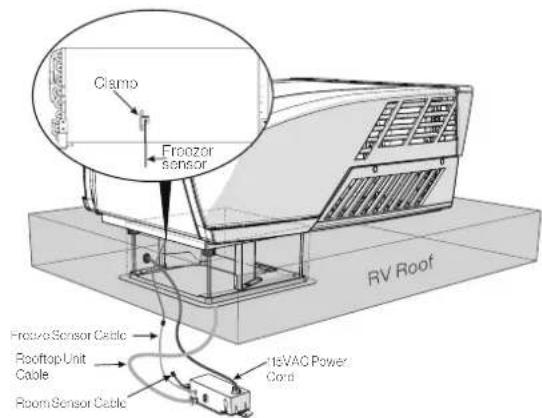
- Locate the 12 VDC power cable (red, tagged with "+12 VDC") and ground cable (black, tagged with "Ground (12 VDC)") of the control box. And connect them with the corresponding 12 VDC wire prepared in the ceiling.
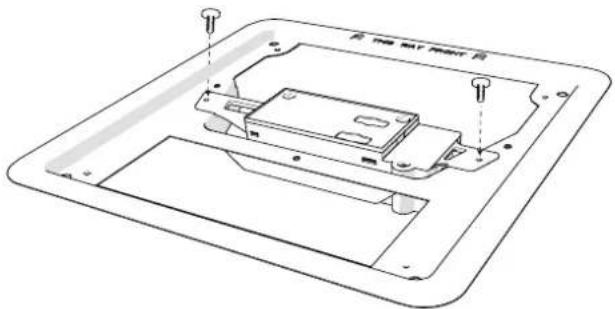
- Install the control box onto the mounting frame and fix with 2 provided "short" screws (one each side).
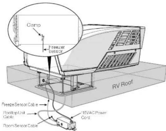
- Stick the freeze sensor into the center bottom of the evaporator. Then insert the clamp into the evaporator between the fins to fix the freezer sensor.
Wire Connection - Multizone
- Determine zone identification for each ceiling controller, and set DIP switches appropriately per the DIP switch selection section.
- Choose the appropriate zone to operate the furnace, for all other ceiling controllers set the Furnace DIP switch to "off" to prevent mis-communication.
-
Repeat the wiring steps covered in the single zone controller for each independent wall controller.
-
Combine all the "To wall thermostat" wires together so that all zones are connected, and each wire function matches. Only one connection point should be made directly to the wall controller / thermostat. Ensure no wire function is crossed throughout the connections.
Analog Connection
The analog connection is only intended for use with OneControl® provided by Lippert Control Systems. It allows connection directly to the HVAC control module without use of a separate gateway box. To connect appropriately:
- Activate the analog harness by turning the DIP switch on as indicated in the DIP switch selection section. This will deactivate the digital "wall thermostat" harness.
- Connect the harness function according to the OneControl® instructions.
- Connect freeze sensor.
Final Installation
- Tuck/secure LED cable (white strip, tagged with "LED") out of the way. This wire is reserved for lighting options.
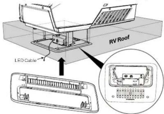
- Install the Air Distribution Box (ADB) shroud over the mounting frame and fix with the 4 provided long screws, or #8 x1.5" (max) pan head RV screws can also be used. NOTE: Make sure the "THIS WAY FRONT" mark is facing front (the direction of the vehicle) while installing.
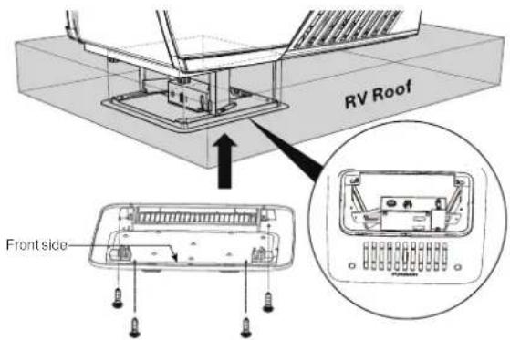
- Align the filter tabs with mating notches and push to snap the filters into the ADB shroud.
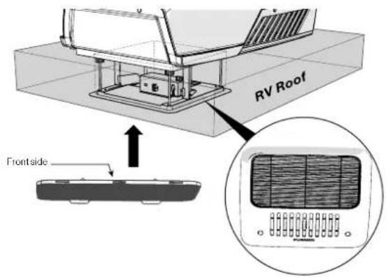
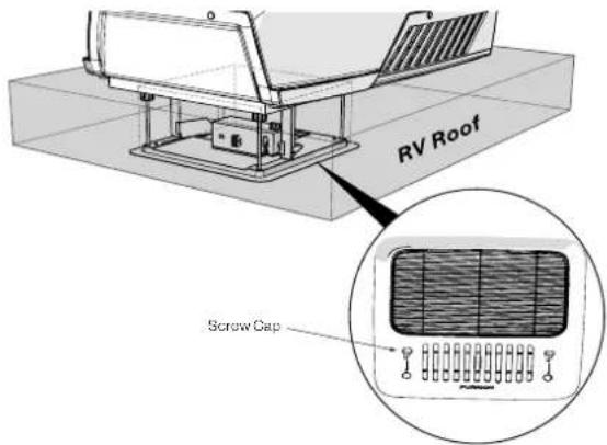
- Install the screw caps to cover the screw holes.
Your new rooftop air conditioner has now been fully installed in the RV roof.
OPERATION
Ducted Systems
Normal Ducted Use
To distribute air through a ducted system, close the air shutter by pushing the tab right to pressurize the duct work.
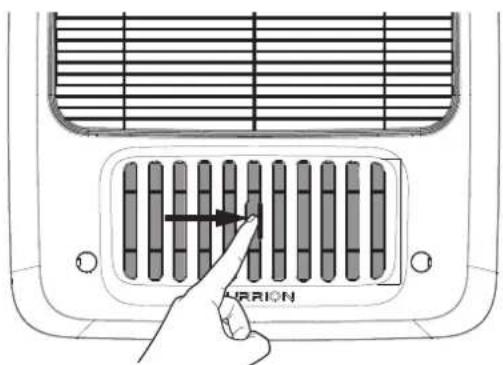
Max Cool
To remove significant heat, open the air shutter to "dump" cool air directly below the AC. This will eliminate air and heat loss in the ducted system, and maximize cooling performance. Once comfortable, close shutter to distribute evenly with the ducted system. Open and close the shutter by pushing the tab left and right.
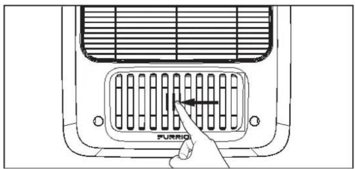
Non-Ducted System
Open shutter to release air.
Thermostat Use
Based on the wall thermostat version you selected. Please refer to the separate instruction manual on how to operate your RV air conditioning system.
CLEANING AND MAINTENANCE
A blocked filter will impair the cooling and heating performance of the unit significantly.
The filter must be cleaned periodically to ensure that it does not become clogged with dust and other particles. The state of the filter can be ascertained from its appearance. If it appears dirty or clogged then it should be cleaned.
WARNING
Airborne particles can pose a health risk, particularly to young children and the elderly. Ensure that filters are cleaned in a safe and well ventilated area.
To Clean the Filter
The filter should be cleaned every four weeks or more when in use. Prolonged use, higher concentrations of airborne particles and various other factors may result in the filters needing to be cleaned more often.
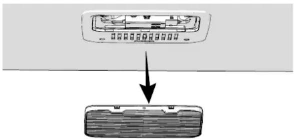
- Remove the filters by pushing the tabs to release. (Fig. 29)
natural_image
Diagram showing a device with an open rear panel and a downward arrow pointing to a closed rear panel (no text or symbols present)- The filter can be washed with warm soapy water. Care must be taken to avoid ripping the fabric.
- Replace the filters and decoration plate, by reversing the above process.
NOTE: The filter must be completely dry before re-installation.
To Replace the Filter
Filter changes should be carried out depending on the amount of use, it is recommended to change at least every 12 months. Never operate the air conditioning system without a filter, since this can decrease performance and indoor air quality. Replacement return air filters can be ordered directly from Furrion.
TROUBLESHOOTING
| Problem Cause | Remedy | |
| Rooftop air conditioner constantly switches itself off | Freeze sensor has tripped. Outer temperature is too low or all air nozzles are closed. | |
| Not cooling well | The rooftop air conditioner is not set to cooling. | Set the rooftop air conditioner to cooling. |
| The set temperature is too high. Select a lower temperature. | ||
| The evaporator fan is damaged. | Contact an authorized service agent or Furrion (see the detail contact info at the back page of this manual). | |
| The condenser fan is damaged. | Contact an authorized service agent or Furrion (see the detail contact info at the back page of this manual). | |
| The air intake grilles are blocked or obstructed. | Remove any leaves and other dirt from the ventilation grilles of the rooftop air conditioner. | |
| The blower is defective. | Contact an authorized service agent or Furrion (see the detail contact info at the back page of this manual). | |
| Water enters the vehicle | The condensation water drainage openings are clogged up. | Clean the drainage openings for condensation water. |
| The seals are damaged. | Contact an authorized service agent or Furrion (see the detail contact info at the back page of this manual). | |
| Rooftop air conditioner does not switch on | No supply voltage connected. Check the power supply. | |
| The voltage is too low. | Contact an authorized service agent or Furrion (see the detail contact info at the back page of this manual). | |
| Fuse blown or circuit protector tripped. | Check the electrical fuse of the power supply. | |
SPECIFICATIONS
| FACR13HESA-**FACR13HESA-**-AM | FACR14SA-**FACR14SA-**-AM | FACR15SA-**FACR15SA-**-AM | FACR15HESA-**FACR15HESA-**-AM | |
| Cooling Capacity (Btu/h) 13,500 14,500 15,500 15,000 | ||||
| Dehumidification (pint/h) | 1.8 | 2.7 | 3.2 | 3.0 |
| Applicable vehicle length (feet) 23 26 31 31 | ||||
| Refrigerant R410A R410A R410A | R410A | |||
| Charge (Oz) | 13.9 | 19.8 | 23.1 | 20.8 |
| Roof top Unit Dimensions (L x W x H) (inch) | 34% x 27% x 13% | 34% x 27% x 13% | 34% x 27% x 13% | 34% x 27% x 13% |
| ELECTRICAL | ||||
| Volts/Frequency | 115V-/60Hz/1Ph | 115V-/60Hz/1Ph | 115V-/60Hz/1Ph | 115V-/60Hz/1Ph |
| Power Watts (Cooling) | 1,283 | 1,620 | 1,720 | 1,760 |
| Amps (Cooling) | 11.3 | 14.6 | 15.4 | 15.6 |
| Power Cord Gauge Min. (mm2) | AWG12 | AWG12 | AWG12 | AWG12 |
| ** Product color. | ||||
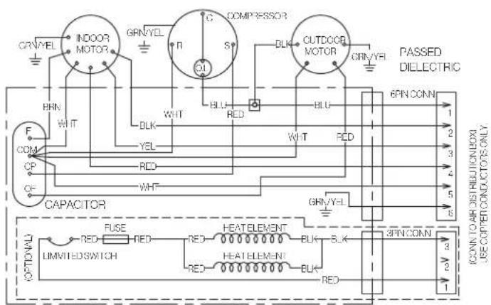
WIRING DIAGRAM
DANGER
Electrical Shock Hazard
- Disconnect power before servicing. Failure to obey this warning could result in death or serious injury.
- Provide grounding in compliance with all applicable electrical codes. Failure to obey this warning could result in death or serious injury.
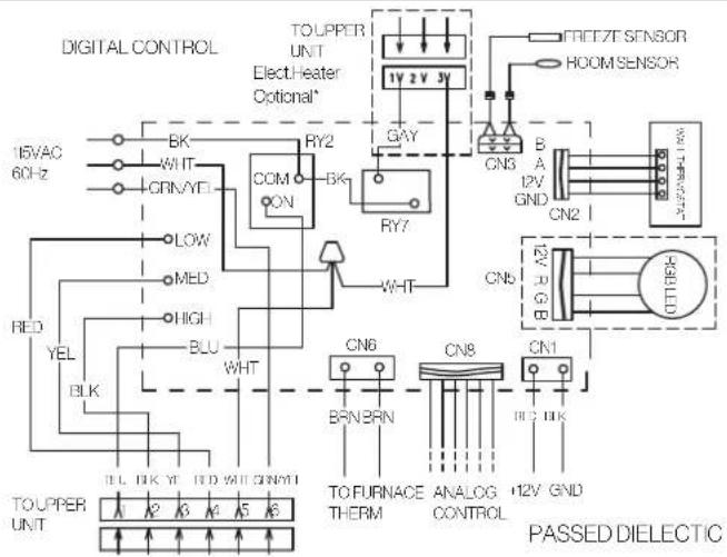
Multi Zone Wiring Diagram
| N° de modèle Furrion N° de Lippert | |
| FACR13HESA-PS 2021132276 | |
| FACR13HESA-BL 2021130013 | |
| FACR13HESA-PS-AM 2021132277 | |
| FACR13HESA-BL-AM 2021132275 | |
| FACR14SA-PS 2021123613 | |
| FACR14SA-BL 2021123563 | |
| FACR14SA-PS-AM 2021123705 | |
| FACR14SA-BL-AM 2021123707 | |
| FACR15SA-PS 2021123799 | |
| N° de modèle Furrion N° de Lippert | |
| FACR15SA-BL 2021123630 | |
| FACR15SA-PS-AM 2021123793 | |
| FACR15SA-BL-AM 2021123708 | |
| FACR15HESA-PS 2021130009 | |
| FACR15HESA-BL 2021130010 | |
| FACR15HESA-PS-AM 2021130011 | |
| FACR15HESA-BL-AM 2021130008 | |
| FACT12CA-PS 2021123541 | |
| FACT12CA-PS-OEM 2022007391 | |
![12" [50cm] 5" 6" 12" [50cm] Duverture du toit](/content/2026/04/631423/images/3e50e0f2ad753a31198c953557fc640d7ad4e297f335956ad8bd049d02fcdd24.jpg)
natural_image
Technical line drawing of a mechanical assembly with mounting base and housing (no text or symbols)natural_image
Technical line drawing of a mounted air conditioner unit with a close-up inset showing internal components (no text or symbols)Ruban adhésif
natural_image
Technical line drawing of a mechanical component with mounting holes and a central housing (no text or symbols)natural_image
Technical line drawing of a mechanical assembly with mounting brackets and a central component (no text or symbols)natural_image
Technical line drawing of a device casing with mounting holes and internal components (no text or symbols)natural_image
Diagram showing a device with an open rear panel and a downward arrow pointing to a closed rear panel (no text or symbols present)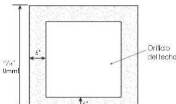
natural_image
Isometric line drawing of a square frame with a diagonal line and a hand holding a curved object, no text or symbols present.natural_image
Technical line drawing of a mechanical housing assembly with mounting brackets and mounting holes (no text or symbols)natural_image
Technical line drawing of a mounted air conditioner unit with a close-up inset showing internal components (no text or symbols)Cinta autoadhesiva
natural_image
Technical line drawing of a mechanical component with mounting holes and a base plate (no text or symbols)natural_image
Technical line drawing of a mechanical device with mounting bracket and base plate (no text or symbols)natural_image
Technical line drawing of a device casing with mounting holes and internal components (no text or symbols)natural_image
Diagram showing a device with an open rear panel and a downward arrow pointing to a closed rear panel (no text or symbols present)natural_image
Abstract black geometric shape on white background (no text or symbols)FURRION
Furrion Innovation Center & Institute of Technology
• 52567 Independence Ct., Elkhart, IN 46514, USA
- Toll free/Numéro gratuit/Línea telefónica gratuita:1-800-789-3341
- Email/Courriel/Correo electrónico: support@furrion.com
©2007-2022 Furrion Ltd. Furrion® and the Furrion logo are trademarks licensed for use by Furrion Ltd. and registered in the U.S. and other countries.
For Patent Info: www.furrion.com/pages/patents


- CONTENTS
- EXPLANATION OF SYMBOLS
- DANGER
- WARNING
- CAUTION
- IMPORTANT SAFETY INSTRUCTIONS
- USA:
- Canada:
- Handling the device
- Handling Electrical Cables
- BEFORE INSTALLING
- What's in the Box
- Choosing Proper Location for the Air Conditioner
- Existing Roof Vent Opening
- New Opening
- After the Location Has Been Selected:
- Roof Preparation
- Fire/Electric Shock Hazard
- Roof Thickness
- Installing in an Existing Opening
- Making a New Opening
- Air Distribution Duct Sizing and Design
- Air Distribution System Installation
- Preparing Wire Connections
- Electrical Shock Hazard
- 115VAC Supply
- 12VDC Supply
- INSTALLATION
- Installing the Rooftop Unit
- Wall Controller Connection (Single and Multizone Thermostat)
- Furnace Switch (Optional)
- Installing the Wall Thermostat
- Installing the Air Distribution Box
- DIP Switch Settings
- Location of the DIP Switch
- Setting DIP Switches
- ! DANGER
- Single Zone DIP Switches:
- Multi Zone DIP Switches:
- Wire Connection - Digital Furrion Wall Controller/Thermostat
- Wire Connection - Multizone
- Analog Connection
- Final Installation
- OPERATION
- Ducted Systems
- Normal Ducted Use
- Max Cool
- Non-Ducted System
- Thermostat Use
- CLEANING AND MAINTENANCE
- To Clean the Filter
- To Replace the Filter
- WIRING DIAGRAM
- FURRION
- Furrion Innovation Center & Institute of Technology
Brand : Furrion
Model : FACT12CAPS
Category : Air Conditioning