Antmix 16FX USB - Mixer ANT - Free user manual and instructions
Find the device manual for free Antmix 16FX USB ANT in PDF.

| Product Type | 16-channel analog mixer with USB interface |
| Brand | ANT |
| Model | Antmix 16FX USB |
| Number of Input Channels | 8 mono channels (with compressor) + 4 stereo channels (2 stereo pairs and 2 additional pairs) |
| Dimensions (W x D x H) | 510 x 400 x 35 mm |
| Weight | Approximately 5 kg |
| Power Supply | 100-240 VAC, 50/60 Hz |
| Power Consumption | 500 W max |
| Microphone Inputs | 8 balanced XLR inputs with +48V phantom power |
| Line Inputs | 8 balanced 6.35mm Jack inputs (mono) + 8 Jack inputs (stereo) |
| Equalizer | 3-band (mono) with semi-parametric filter, 4-band (stereo) |
| Built-in Effects | 100 DSP effects (reverbs, delays, chorus, etc.) |
| USB Interface | USB type B port for recording and playback from a computer |
| Main Outputs | 2 balanced XLR + 2 unbalanced Jack (MAIN MIX) |
| Auxiliary Outputs | 4 AUX sends (balanced Jack) + 4 stereo returns (Jack) |
| Group Outputs | 4 GROUP OUT (Jack) |
| Headphone Output | 2 stereo Jack 6.35mm outputs with dedicated volume |
| 2-Track Input/Output | RCA input and output (2-TRACK) |
| Compressor | On channels 1 to 6, adjustable threshold from 0 to -10 dB |
| Low Cut Filter | 75 Hz on channels 1 to 12 |
| Phantom Power | +48V switchable for all microphone channels |
| Maintenance and Cleaning | Disconnect the device before cleaning. Use a dry, soft cloth. Do not use chemicals. |
| Safety | Only use the supplied power cord. Do not open the device. Risk of electric shock. |
| Spare Parts and Repairability | Contact an authorized service center. Do not attempt to repair yourself. |
Frequently Asked Questions - Antmix 16FX USB ANT
User questions about Antmix 16FX USB ANT
0 question about this device. Answer the ones you know or ask your own.
Ask a new question about this device
Download the instructions for your Mixer in PDF format for free! Find your manual Antmix 16FX USB - ANT and take your electronic device back in hand. On this page are published all the documents necessary for the use of your device. Antmix 16FX USB by ANT.
USER MANUAL Antmix 16FX USB ANT
- 1 x Mixing console - 1x User manual - Section 1
- 1x Mains cable with VDE plug - 1x User manual - Section 2
The warnings in this manual must be observed together with the "user manual - Section 2".
1 | INTRODUCTION
Thank you for choosing a A.N.T - Advanced Native Technologies - product
In ANTIMX series of mixing consoles we have put our pass on and our technological background gained over the years, to offer products that meet your needs, and maintaining the quality over time.
All the models as this series represent a solution rich of features and optimisly bleo professional features with great quality and exceptional value as the adreavces internal DSP with different effects and variations, the built in compressor for main microphone inputs, 60 mm ladda as well as a series of UO to Luill a wide range of applications.
Both models feature a USB port allowing connections to a computer or a tablet.
Specifically designed for an immediate and user friendly use, these mixers satisfy the needs of those who want an audio mixer providing excellent performances, twice versatility of connections and controls as well as the best value for this range of products. Please dedicate some minutes to read this instruction manual in order to quickly achieve the best performances from this product. For safety precautions, warranty and disposal, please refer to attached Section 2.
For further information about all A.N.T products catalog please visit our website www.ant-intomusic.com
2 INSTALLATION
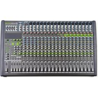
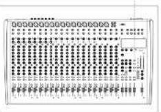
ANTMIX 16FX USB / 24FX USB models
are provided of
A | Metal rough and light chassis.
B ABS side panels with
ergonomic hande
C|Front panels for optional boards
-MFX1624(MP3player)or
31X1624(BuToot module)


3 DESCRIPTION
3.1 MIXER CONTROLS & CONNECTIONS
3.1.1 MONO/STEREO INPUTS
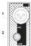
1 MIC INPUT
XLH-Balanced microphone input.
2 MONO LINE INPUT - CHANNELS FROM 1 TO 8 (16FX USB) / FROM 1 TO 16 (24FX USB) 3.35mm . (174) balanced line input. You may also use an unbalanced cable.
3 STEREOLINE INPUT - CHANNELS FROM 9 TO 12 (16FX USB) / FROM 17 TO 20 (24FX USB)
Two 6.30 min. (1/4) balanced line input. Connecting only one cable to LMONO, it becomes a mono channel. You can also use an unbalanced cable.
4 INSERT - CHANNELS FROM 1 TO 8 (16FX USB) / FROM 1 TO 16 (24FX USB)
6.53 mm ( T^ / T^ ) TRS sockets. This socket allows you to connect external devices (e.g., a compressor, an EO, etc.) to process the signal. For this connection use a T^ cable, plugging to this socket's TRS connector (tip = send, ring = return, and sleeve = ground) then connect the external device with two TS connectors, one for input and one for the output.
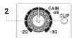
5 GAIN & CLIP LED
This knob adjusts the gain of the microphone or line signal, turn it to the right to raise the level or to the left to decrease it.
The CLIP-ED is at when the rpsu signal is too high
COMP & LED - CHANNELS FROM 1 TO 6 (16FX USB) / FROM 1 TO 8 (24FX USB)
This knob simulates a compressor pressure threshold and ratio. Turning the knob hard left, the compressor is turned off, turning to the right you activate it, until the maximum compression is 1 + 10 . Use this control, for example, to make voices levels more homogeneous. The LF next to the knob lights up when the compressor is activated.
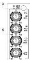
7 LOW CUT-CHANNELS FROM 1 TO 12 (16FX USB)/FROM 1 TO 20 (24FX USB)
This switch activates the hi-pass filter to reduce the frequencies from 75Hz down. Use it to avoid that microphones connected to the input channels will pick up unwanted signals rich of low frequencies.
8 EQ-CHANNELS FROM 1 TO 8 (16FX USB)/FROM 1 TO 16 (24FX USB)
Use this three-band equalizer to boost or cut the high, mid and low frequencies to get the best mix in any environment. The semi-parametric FREQ control allows frequency selection from 100 Hz to 8 kHz.

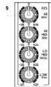
9 EQ-CHANNELS FROM 9 TO 12 (16FX USB) / FROM 17 TO 20 (24FX USB)
Use this four-band equalizer to boost or cut the high, mid and low frequencies to get the best mix in any environment.
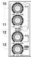
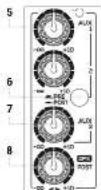
10 AUX 1 & 2
These knobs adjust the signal sent to AUX SEND 1 and 2. both sends can be set pre/post fader.
11AUX 1 & 2 PRE/POST
This selector determines whether the AUX1 and 2 send level is independent (PRE) or is influenced (POST) by the channel level control. Generally it is used PRE to send the signal to stage monitors or EIM. POST to send the signal to an external effect unit.
12 AUX 3
This post-fader send, i.e. dependent on level control of its channel, allowing to adjust the signal sent to an external effect unit or to a monitor connected to the AUX SEND 3 output.
13DFXPOST
This send, in fluenced by the individual channel level control, adjusts the signal sent to the internal effects or to an external effects connected to DFX SLND output. Furthermore, the DFX POST control can be used as the fourth auxiliary send (activating the internal effect via the DFX MU-TL button) for connection to an external affects unit connected to the AUX FSD 4-1 output.
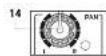
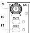
14 PAN - CHANNELS FROM 1 TO 8 (16FX USB) / FROM 1 TO 16 (24FX USB)
This knob acjuts the signal position in the stereo field.
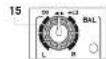
15 BAL - CHANNELS FROM 9 TO 12 (16FX USB) / FROM 17 TO 20 (24FX USB)
The BAL knob sets the left-right balance for stereo channels.
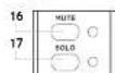
16 MUTE & LED
Press this button to mute the selected channel source.
The lit LED indicates the MUTF activation.
17 SOLO & LED
Press this button to check channel signal level before the fader.
It works also when the channel is muted; the led indicates the activation of the command.
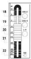
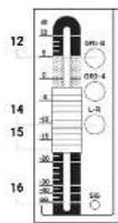
18GR1-2
Press this button to route the channel signal to GROUP CUT 1-2 outputs
19GR3-4
Press this button to route the channel signal to GROUP CUT 3 4 pulps
20 L-R
Press this button to route the channel signal to MAIN MIX L-R outputs.
21 VOLUME
Use this fader to adjust over all channel volume.
22 SIGLED
This led a light when the input signal is very strong and it's close to distortion. If the LED is continuously lit, you need to reduce the VOLUME of the fader or cut the channel LC by reducing the boost introduced by the HI-MID-LOW tone gains.
3.1.2 STEREO INPUTS
13/14-15/16 (ANTMIX 16FX USB) / 21/22 - 23/24 (ANTMIX 24FX USB)
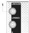
1 LINE L (MONO) & R INPUT
Twe 6.35 mm [14] balanced line input.. Connecting only one cable to LIMONO it becomes a mono channel. You can also use an unbalanced cable.
2 GAIN & CLIP LED
This knob adjusts the gain of the microphone or line signal, turn it to the right to raise the level, or to the left to decrease it.
The CLIP FD is at when the input signal is too high.
3 LINE/USB
Press this switch to assign channels 15/6 (16FX USR) and 23/24 (24FX USR) to the USF interface and receive the audio signal from the computer connected to the unit. In the LINE position, key reuses, the channels are normally assigned to the respective inputs jack
4.50
Use this four-band equalizer to boost or cut the high, mid and low frequencies to get the best mix in any environment.
5AUX1&2
These knobs adjust the signal sent to AUX SND1 and 2. Both sends can be set pre-/post-fader.
6 AUX 1 & 2 PRE/POST
This selection determines whether the AUX 1ans 2 sand level is independent (FPE) or is influenced (POST), by the channel level control. Generally it is used PR to send the signal to stage monitors or EM POST to send the signal to an external effect unit.
7.AUX3
This post-factor stand, i.e. dependent on level control of its channel, allowing to adjust the signal sent to an external effect unit or to a monitor connected to the AUX-SEND-3 output.
B DEX POST
In this send, influenced by the individual channel, event control adjusts the signal to the internal effects or to an external effects connection to DI-X SEND output. Furthermore, the DI-X POST control can be used as the fourth auxiliary send (deactivating the internal effect via the DI-X MUTE button) for connection to an external effects unit connected to the AUX SEND 4 output.
9 BAL
The BAL knob sets the left right balance for stereo channels.
10 MUTE & LED
Press this button to mute the selected channel source.
The lit Fd indicates the MTF activation
11 SOLO & LED
Press this button to check channel signal level before the fader.
It works also when the channel is muled; the led indicates the activation of the command.

ANTMIX SERIES
12GR1-2
Press this button to route the channel signal to GROUP CUT 1-2 outputs
13 GR 3-4
Press this button to route the channel signal to GROUP CUT 3-4 outputs.
14L-R
Press this button to route the channel signal to MAIN MIX L-R outputs.
15 VOLUME
Use this lader to adjust overal channel volume.
16 SIG LED
This led light when the input signal is very strong and it's close to distortion. If the LED is continuously lit, you need to reduce the VOLUME of the ladder or cut the channel EQ by reducing the boost introduced by the H1 MID-LOW tone gains.
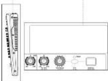
3.1.3 POWER SUPPLY AND MASTER SECTION
1 2-TRACK IN
Unbalanced line input with BCA L/R sockets.
Connect to this socket the output of a hi- equipment (CD) or other device with RCA outputs.
2 2-TRACK OUT
unbalanced line output with FCA L/R sockets
Connect these outputs to a h-f device, e.g. a recorder; the volume is set by MAIN MIX output.
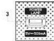
3 POWER LAMP
USB socket to power a lamp with a voltage of 5V - 500mA
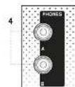
4 PHONES
Output for connection to two headphones (A & B) with 8.35mm. (1/4") stereo jack.
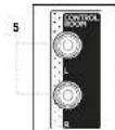
5CTRL/R
CONTROL ROOM output with two 6.35 mm (1/4") the sockets. This output section collects the signal from the CTRL ROOM/SCURCE section, in studio applications, the typical use is for studio monitors but can also be used to drive a second group of powered coexcers with level control independent from the master, thus creating two distinct listening areas at different volumes. The volume of this output is adjusted using the CTRL /ROOM knob regardless of the MIN/MIX output volumes.

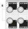
6 AUXSENS1,2,3AND4
6.35 mm.(1/4) output loop of relevant Aux sends 1,2,3 and 4
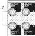
7 GROUP OUTS 1,2,3 AND 4
Outputs of the respective groups on a 8.33mm(1/4) balanced jack. These outputs allow to drive a second group of amotile loudspeakers with level control independent from the master, thus creating more distinct listening areas with different volumes or directing the selected signals to a recorder / sound card.
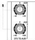
8DFXTOAUX1/AUX2
These kncb set the signal level of the internal effects unit for AUX 1 and 2 sands.
Use them to increase or decrease the amount of processed signal.
9 TO DFX ST. OUT
This block allows you to send the output of the internal effects, in the rear panel dedicated output;DFXST OUT. Connect this output to your external effects units if any. The output signal is the sum determined by the DFX sends for each camera.
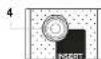
10 PROGRAM (PUSH)
This 100 position selector allows you to choose the
type of effect.
Turn the knob until you reach the desired program.
then press the knob to activate the selected effect
The first 10 programs called FC-O reproduce the classic echo effect with increasing decay in the subsequent variants, ECHO = VERB algorithm simulates a combination of echo and reverber. the impress vs effct used in many musical productions, the TREMOLO effects are mostly used on stringed instruments, while PLATE, CHORUS, and VOCAL programs offer a pleasant sound widening and are able to strengthen vocals. The ROTAYOY effects simulate live organ, while the SMALL 1000M programs recrere the reverberation of rooms with similar dimensions to those of residential rooms, alternating the simulation of reflective and absorbent walls. The FLANGER + RUV section represents a combination of effects perfect for different instruments, in particular keybosts, and finally the LARGE HALL effects package simulate the reverberation of environments with large volumes characterized by mostly reflecting naked wells.
11DEXDISPLAY
This display shows the numbers corresponding to selected effects by the PROGRAM (PUSH) encoder.
12 PEAK
This LED is lit when the signal sent to DFX is too high, and there's a risk to saturate the internal effect. It's a good setting of the effect sends when the LLD flashes occasionally, only on signal peaks. When the LLD remains continuously it is an indication of saturation. In that case please cut the volume of DFX-POS1 channel sends.
13 DEX MUTE
This button allows you to enable or disable the return signal of the internal effects unit.
ANTMIX SERIES
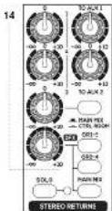
14 STereo Returns 1-2-3-DFX
Master evel controls for the auxiliary STEREO RETURNS:
-1:ControlsSTERORETURN1levelsentto theMAIN MIX OUTPUT
-210030STEP50RETOF21eHSEHCTHEMIXCUPOT
-3. CONTROL SCHEDULES 1.1.1.1.1.1.1.1.1.1.1.1.1.1.1.1.1.1.1.1.1.1.1.1.1.1.1.1.1.1.1.1.1.1.1.1.1.1.1.1.1.1.1.1.1.1.1.1.1.1.1
- DFC: Controls DFC OUT level and the STILERO RETURN 4 assignable, by the 3 lateral keys, to groups 1-2 (SH 1-2), groups 3-4 (SR 3-4) and MAIN MIX output. By pressing the STILERO RETURN SOL button (with -ED) all STEREO RETLINS insert SO.0 mode and their mixed signal is sent into the CONTROL ROOM and to PHONES A B outputs
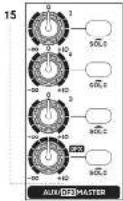
15 AUX/DFX MASTER & SOLO
Controls the master levels of the respective auxiliary sends and the DFX send (internal effect). Press the SOLO button to pre-14, their signal is sent to the CTRL ROOM and PHONES A-B outputs.
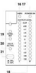
16+48V
This LED is lit to when Phantom 45V is activated.
17 POWER ON
This LED is lit green when the mixer is ON.
18 OUTPUT LEVEL
MAIN OUTPUT LEVE (LED indicators). The L indicator can also work to control the level in SOLIC. When the CLIP LED lights up, the output signal level is too high.
19 LED LEVEL SET
When this LLD is on, the OUTPUT LEVEL L LD bar indicates the input level of the channel in SOLS-PFL mode, level can be optimized by the GAIN control of the selected channel.
20 LED SOLO ACTIVE
When it's lit, one or more channels and/or one or more auxiliary aux sends are selected in SOLO mode.
21 PFL/AFL BUTTON
It always shows the choice between two types of SOLO for the CTRL ROOM and PHONES A B outputs. When it is released (FPL = "pre-fader listening"), you can listen to the audio signal before the Fads. This mode is useful to check the input level of the channel in SOLO via the main LLD meter, and optimizing the gain accordingly. When it is pressed ("AFL = "after-fader listening"), it is possible to hear the "mixing" of channels(s) and the relevant AUX auxiliary sends placed in SOLO, keeping current levels and pans adjustments.
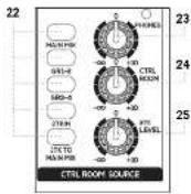
22 MAIN MIX/GR 1-2/GR 3-4/2 TKIN
Press the key(s) of the signal(s) you wish to listen via the CONTROL COM
23 PHONES
This knob controls the volume of the headphones connected to the PHONES A-B outputs.
24 CTRL RDOM
This knob controls the level of the CON ROL ROOM outputs (eg pair of studie monitors).
25 2TK LEVEL
Level control of 2KT-IN stereo input (RCA connectors) or from directional Bluetooth cards or USB player).
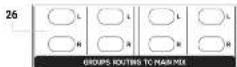
26 L & R GROUPS ROUTING TO MAIN MIX
Pres the L and R buttons to assign the group signal to the MAIN MIX output.
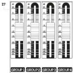
27 GROUP OUT 1-4
These faders independently adjust the output level of the four groups, which can be used both as master levels for recording and to drive other powered speakers to create distinct listening areas at different volumes.
28
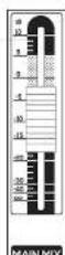
28 MAIN MIX
Adjust this fader to set MAIN MIX OUTPUT level

ANTMIX SERIES
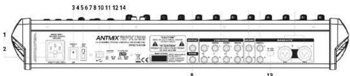
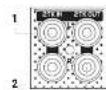
1 MAINS INPUT
Plug into this socket the mains cord supplied with the unit. Make sure the unit is Lined OFF before connecting the cable to the maina. For your safety, never disconnect the earth lead.
2 FUSE
Prolechon use.
WARNING Replace the use only with one of the same type and with the same value
If the fuse blows repeatedly, contact an authorized service center
3 POWER ON/OFF
Press this switch to turn ON or OFF the unit.
4+48V
This switch allows you to use the phone power for sound and microphones.
O=SwitchIumedONfengssxInthe Icm)+42VLEDU
P=Switch turnedOff+88VLED turned off
5 USB PORT
This type B USB port allows connection to a computer or other audio device with a JSB interface.
6RECORD
This selector allows you to choose the signal to send to the device connected to the USB port. Set it to MAIN MIX when you want to record the signal assigned to that stereo or to SR 1-2 when you want to record the signal assigned to that stereo group.
7 PLAYBACK
Use this selector to choose the sign you want to hear from the device connected to the USB port. Set it's switch to MAIN MIX to send the audio signal coming from the computer (or from the connected audio device) directly to the MAIN MIX output or to CH 13-6 (ANTIMIX 16FX USB) / CH 23-24 (ANTIMIX 24FX USB) to assign it to the above mentioned channels. NOTE: if you assign the USB audio signal to channels 15-16 / 23-24, listen to the LINE / USB switch (3) on the front panel and choose...SUB. NOTE: to avoid digal caps when overdressing, assign the RECORD switch to GF1 - 2 and the PLAYBACK speaker on the stereo channel 15 / CH 23 -24 assigning it only to GF3 - 4 or MAIN MIX.
8 DEXSTOUT
The signal from the internal effects processor is present in this balanced stereo output, 6.35mm jack
9FOOTSW.
Connect an external pedal to this unbalanced jack for inserting or excluding internal effects. Press once to deactivate the effects (DFXMUTE function), press a second time to reactivate them.
10STEREORETURN(S)
Connect to these input jacks the return of an external effects unit or other stereo or mono device. For each STERLO RETURN auxiliary return (1-2-3-4) there are two audio inputs -L (MONO)/R - on 6.3mm balanced accoders
11 MAIN INSERT
6.35mm, jack sockets for insertion of external processors (eg EO or compressors) in the MAIN circuit. The tip of the jack sends the signal to the processor, the ring receives the processed signal, while the sleeve has the signal of both grounds.
12 MAIN MIX OUT
6,35mm unbalanced jack outputs. Connect the inputs of your amplification system or master recorder to these outputs.
13+4dBU/-30dBU
This selector allows you to select the output level between 14 dBi and -30 dBi to optimize the connection for any destination.
14 MAIN MIX OUTPUT
Balanced XLH-M outputs. Connect the inputs of your amplification system or master recorder to these outputs.
3.1.4 USB INTERFACE & APPLICATIONS
1 RECORD
Select the source for recording between SH1-2 and MAIN MIX.
MAIN MIX is ideal for recording a live session or basic tracks (fry hm or other) while during over doubling it is advisable to record from SR1.2 and use MAIN MIX for direct listening
NOTE: to avoid annoying looks, never choose MAIN MIX when playback is on MAIN MIX. Do not route the GTR1-2 signal to MAIN MIX.
2 PLAYBACK
Allow you to select the channels to listen the US$ port signal. During playback and/or overdute, it is admissible to listen via CH115-6 (23-24) both to give the right level to each AUX that equalize. MAIN MIX is ideal for audience listening and for the final mixing.
NOTE: If you desire to listen to the USB port signal, beside sending this swcon to CH15-16 (CH23-74) you have to press the USB key of the relative stereo channel of the mixer.
APPLICATION
Playback
Set the selector to PI. AYBACK on CH15-16 (or CH33-24) and press the USB key of the last: silencer channel (15-16 or 23-24) to listen to the psychoTrack signals from PC/tablet. In this way you can adjust signal for monitors and musicians, via AUX1 and 2 independently of the MAIN MIX levels (possibly also AUX 3 but remember that it is past fader) and equalize the signal!
Karaoke
Set the access to PLAYBACK on CH 5.16 (or CH 23-24) and press the USB key of the last, silence channel (16 or 23-24) to listen to the playback tracks signals from PC/RTabit. In this way you can adjust signals for monitors and musicians, via AUX1 and 2 independently of the MAIN MIX levels (possibly also AUX 3 but remember that it is post-talker) and equalize the signal.
Recording
SetRECORDtoMAINIX,and assign thechansesyouwant torecordtotheL-IRoutpuandadjustthe volumes. Assign lineigns youdo notwant to record toGR3-4and adjust this signal for the headchones of the musiels via line AUX sords
Overdub
Set the RECORD selector to CR1-2 and assign the channels you want to record to the CR1-2 output and adjust the volumes.
For listening pull P.AYBACK on CH16 16 or CH23 24 and press the USB key of the best stereo channel (15 16 or 23 24) to listen to FCDctable playback tracks. Adjust the signal for the musicians' nasophones via the AUX I, 2 and 3 sends (there is no risk of feedback in the headphones)
Assign the signals you do not want to record to GR3-4 and adjust the signal for musicians' headphones via the AUX senses.
Mixing
You can make an IIT mix and listen either through the last stereo channel, by setting PI.AVBACK on C11-16-18-24. In this way you can do minimal FQ adjustments. Otherwise you can set the PI.AVBACK on MAIN MIX to listen with no action except volume adjustment.
3.1.5 OPTIONAL BLUETOOTH & MP3 PLAYER BOARDS 4 | TROUBLESHOOTING
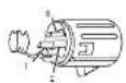
BOARDS INSTALLATION
The installation is very simple, but if you have no experiences, contact a specialized service center.
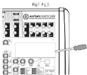
WARNING: for your safety operation turning off the mixer and uncoupling the appliance from the mains socket. With a flat-pressed screwdriver, press gently under the plastic cover and pry up the right side to remove carefully (Fig. 1). To install the optional M-PX 1524 or BTX 1524 card, connect the s-pin connector cable to the respective s-pin connector on the printed circuit board of the mixer (Fig. 2). At this point it is sufficient to hook the optional module in the appropriate housing and take advantage of the new functions.
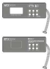
BLUETOOTH® MODULE-BTX 1624
Activate the Bluetooth of your device and press the PAIR button of the board. The source device should recognize the board as BT 4.0 and synchrotron automatically. In the mixer, press the 21K ICM MAIN MIX selector t'ren gracally raise the 21K LEVEL knob and the MAIN MIX facer until you reach the desired volume. You can also control the volume from the Bluetooth card itself, using the VOL- and VOL+ keys, using the -I and PAUSE: the key you can choose the track to listen to or pause it.
MP3 PLAYER MODULE - MPX 1624
In a USB slot, loc all the tracks you want (up to 32Gb), even in multiple folders. Inser: the stick into the USB port of the colonial board by simply pressing the PUSH & HOLD button for 2 seconds to start playing the ladder from the first track. The display will ultimately show the number of the file and its folder
To listen to the previous song just press▶, while to listen to following track press▶. Holding down the keys you can change the folder. The▶ key pause or resume the song. If you press stop▶, payback will be totally skipped. If you press more times the▶, you can choose random play, a single song play or all tracks play.
In the mixer, please press the 2TK TO MAIN MIX selector; then gradually raise the 2TK LEVEL inch and the MAIN MIX fader until you reach the desired listening volume.

| PROBLEM LED SOLUTION | ||
| No sound or very clear sound level | Power LED turned off | Make sure the device is properly connected to the main cable. |
| Power LED turned on at MAIN MIC over Rabe MAX MIC level. | ||
| Power LED turned on MAIN MIC+VOL raised, but MUI-Button depressed | Rabe MAX-Button | |
| Power LED turned on MAIN MIC+VOL raised, but input channel FPH-OUT | Check components between sources and mixer. Raise mixer FPH. | |
| Power LED turned on MAIN MIC+VOL raised, but FPH-OUT | Activate 148V power for microphones discharging it | |
| Power LED turned on MAIN MIC+VOL raised, but signal added to OT-1 or OT-3 are not addressed to MAIN MIC | Press the L-R button over OT1, OT2, OT3 and/or OT4 holes | |
| No effects heard | DXT-MUTC value | Turn off the DXT-MUTC button, are check send levels of all the channels |
| DXT-MUTC deactivated | Check the levels of DXT-FICTUP as well as OT-1, OT-3 and MAIN-MIX session buttons. | |
| No Rx signal in monitors | 0-KMILL-distributed check (DK) C-MIN L and 0-KX 10 AUX 2 mobile levels | |
| Stimulation (P&K IHDin) | Reset the level of the inputs and main MAX MIC. Check you have connected a microsignal into MTCG socket. | |
| Cyclic sound | Make sure you have continuously activated more sound sources at the same channel | |
| Check if your activated microphones L&W/CUT line | ||
| Check that LINE-AUX parameters of the stereo channel 1b-1b (ANIMB 1b-1b-LW4) or 2b-2b are not connected to MAIN MIC while you're listening to OMB signal in MAIN MIC. | ||
| Recorded signal in ears heard | Check that LINEUSD seconds of the stereo channel 1b-1b (ANIMB 1b-1b-LW4) or 2b-2b are not connected to MAIN MIC. | |
| No recording | Check that LINE-AVACI oscillator is answered to control output (A7A7 or OT-1) and that desired signature is addressed to the right direction. | |
| Loop in recording | LINE-AVACI stereo channel 1b-1b (ANIMB 1b-1b-LW4) or 2b-2b (ANIMB 1b-1b-LW4) is processed and the line-AVACI oscillator is answered to the wrong spatiotemporal (MAIN or OT-1) | |
5 | TECHNICAL SPECIFICATIONS
| ANTMIX 16FX USB ANTMIX 124FX USB | |
| Mono microphone input B with compressor B with compression | |
| Stereo microphone input L2 | |
| Stereo line input 23 | |
| Power supply H30 2000 AD H30 2700 AD | |
| Power allocation hkl/min 720 min | |
| Dimensions (N×H×D) | 515×460×35mm 20.85×18.11×35.40" |
| Weight 7kg - 15.42 lbs 5.7kg - 21.39 lbs | |
| Microphone input | |
| Connector XLP-T balanced | |
| Impulse rate 1 kHz | |
| Frequency response 20~20kHz A+1:5 | |
| Distortion THD = N-0.03% @ +30.22 kΩ A weighted | |
| Gain | 0~5dB |
| Max input | +6dB (balanced) |
| Low-out | 70Hz 120dBc |
| Signal to noise ratio | × 100 dB A weighted |
| Flat-rate powering | ≈40V |
| Line Input | |
| Connector (power [1/2] balance) 40A inchodanced | |
| Impulse 120Hz or higher | |
| Frequency response 20~20kHz L1B | |
| Distance THD = N-0.03% @ 100k 22-27 kΩ A weighted | |
| Gain | +10dB-1dBc |
| Sign-to-noise ratio | ≈100 cD A weighted |
| Common features | |
| Compression For channel setting compression | |
| Lum & notes | < -300A weighted for band-pass filter and PAANG (G & G) other channels guide |
| Crosstalk | a. 800A weighted full band with 1 channel and 100 channels and 100 channels on channel guide |
| EQ | |
| Mono & microsystem channels | -/-5 dB @12 kZ / -b@p @100+/-b@p / -b@p @100- |
| Strobe channels | -/-8 dB @12N+/-b@p / -b@p @100+/-b@p / -b@p @100- |
| 2-TRACK IN | |
| Connector 2 x RCA unbalanced | |
| Impulseon 13 kHz | |
| Frequency response 20~20kHz +/-1:5 | |
| Distortion (THD = N-0.03% @ +30.22 kΩ A weighted | |
| Gain | -0T→150 |
ANTMIX SERIES
6 | CONNECTORS
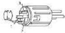
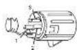
A BALANCED XLR-M MICROPHONE INPUT-MONO AND MONO/STEREO CHANNELS
1-ground
2 positive (or hold)
3 negative [or cold]
B TS JACK
DFXSEND-Master section
STEREO RETURN - Master section
CONTROL ROOM - Master section
DEX MUTE - Master section
MAIN MIX OUT
GR1,GR2,GR3andGR4OUT
AUX1,AUX2,AUX3 and DFX SEND
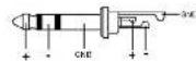
C TRS JACK Line Input - all channels
D BALANCED XLR-F MAIN MIX OUT
1 ground
- positive (or not)
3-negative [or cold]
E TRS JACK
Insert - mono channels

F RCA PLUG
- TRACK IN: Master section
2 TRACK OUT: Master section

G STEREO JACK
Phone - Master section
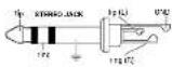

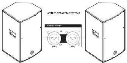
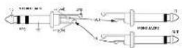
FIG.B|MAINMIXOUT
Connect MANIMIX outputs to powered speakers or amplifiers
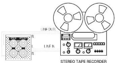
- 2TK IN / 2TK OUT
connel your recordor lo 2TKIN (rrom recordor output) and lo 2TKOUT (to record input) connceler.
8 NOTES

ANTMIX SERIES
INDICE
3.1.4 | INTERFACUSB & APPLICATIONS
1. RECORD
1 Mass
2 Signal + (order hei)
3 Signal - (open kalt)
E KLINKENSSTECKER SYMMETRISCH
Insert-Monokanale
F CINCH-STECKER
ZTRACKIN Master Section
2 TRACK OUT - Master-Sektion

G STEREO-KLINKENSSTECKER
IN MIX/GR1-2/GR3-4/2TKIN,
Pulse acte de la sera [los borones de las sestales]; que desire esecarizar mediante CONICRL. RCM.
23 PHONES
ENG The information contained in this manual have been carefully drawn up and checked. However no responsibility will be assumed for any inconvenience. This manual cannot cover all the possible contingencies which may arise during the product installation and use. Should further information be desired, please contact us or our local distributor. A & B, Industrials Srl can not be considered responsible for damages which may be caused to people and things when using this product. Specifications and features as a subject to change without prior notice.
Tt t t t t t t t t t t t t t t t t t t t t t t t t t t t t t t t t t t t t t t t t t t t t t t t t t t 0
The Bluetooth® word mark and logos are registered trademarks owned by the Bluetooth® SIB, Inc. and any use of such marks by AER Industries, S.R.L. is under license. Other trademarks and trade names are those of their respective owners.
END Download this manual in other languages on www.ant intomusic.com
POR - Date estemulam em outos idiomss enwwantinmuaic com
CES - Stammete stentm manuay jychjazyoch na sceee www.arn-mnncic.com
POE - POET2 (nsh) 100000000000000000000000000000000000000000000000000000
Made in China
Made in China
Fabrique en Chine
Fabrikadun China