ATG4W - Cooker AYA - Free user manual and instructions
Find the device manual for free ATG4W AYA in PDF.
| Product type | Built-in gas hob |
| Brand | AYA |
| Model | ATG4W |
| Number of burners | 4 (1 rapid, 2 semi-rapid, 1 auxiliary) |
| Dimensions (W x D x H) | 600 x 510 x 95 mm |
| Weight | Approximately 10 kg (estimate) |
| Power supply | 220-240 V ~ 50-60 Hz, 2 W |
| Total power | 7.5 kW (546 g/h) |
| Rapid burner | 3.0 kW (219 g/h) – pan diameter 200-240 mm |
| Semi-rapid burner | 1.75 kW (127 g/h) – pan diameter 160-180 mm |
| Auxiliary burner | 1.0 kW (73 g/h) – pan diameter 120-160 mm |
| Ignition | Automatic with safety device (thermocouple) |
| Compatible gas type | LPG (G30 29 mbar) and Natural Gas (G20 20 mbar) – convertible |
| Gas connection | G1/2" female |
| Worktop cut-out | 560 x 480 mm (minimum) – refer to the manual |
| Hob material | White enamel |
| Maintenance | Clean with a soft cloth and neutral detergent; do not use abrasives |
| Safety | Anti-extinction safety device (gas cut-off if flame goes out) |
| Legal warranty | 2 years (conformity) |
| Supplied accessories | 4 fixings, 4 adhesive gaskets, 4 screws, 4 injectors, manual, angled connector |
Frequently Asked Questions - ATG4W AYA
User questions about ATG4W AYA
0 question about this device. Answer the ones you know or ask your own.
Ask a new question about this device
Download the instructions for your Cooker in PDF format for free! Find your manual ATG4W - AYA and take your electronic device back in hand. On this page are published all the documents necessary for the use of your device. ATG4W by AYA.
USER MANUAL ATG4W AYA
natural_image
Two white gas stove appliances with four circular vented gauges, mounted on a control panel (no visible text or symbols)natural_image
Simple diagram with a circle, star, and curved arrows (no text or symbols)natural_image
Four identical diagrams showing a circle with arrows and star symbols, arranged horizontally (no text or labels)text_image
Exploded view diagram of a mechanical assembly with numbered parts for identificationtext_image
45 mm 25 mm (MIN.)natural_image
Pure mechanical diagram showing a lever and pivot point without any text or symbolsLe rail de gaz
masc
∅11,5 Raccord femelle(Non inclus)
natural_image
Symbol of a trash bin crossed with no text or numbers, representing waste sorting or disposal (no text present)natural_image
Two white gas stove covers with black circular vented gauges, mounted on a control panel (no text or symbols visible)Gas hob
TABLE OF CONTENTS
Important safety warnings -2-
Description of the appliance - 5-
Cleaning and maintenance -9-
Installation of the applianc -1 -e
Troubleshooting -18 -
THIS PRODUCT IS FOR HOUSEHOLD USE ONLY!
Please read these instructions carefully before the first use of this product and save this manual for your future reference.
IMPORTANT SAFETY INSTRUCTIONS
- This appliance is intended to be used in household and similar applications such as:
– staff kitchen areas in shops, offices and other working environments; - farm houses;
– by clients in hotels, motels and other residential type environments; - bed and breakfast type environments.
- The plug must be remained easily accessible after installation of the appliance.
- If the power cable is damaged, it must be replaced by the manufacturer, its after-sales service or a qualified technician in order to avoid any danger.
- This appliance can be used by children aged from 8 years and above the persons with reduced physical, sensory or mental capabilities or lack of experience and knowledge if they have been given supervision or instruction concerning use of the appliance in a safe way and understand the hazards involved. Children shall not play with the appliance. Cleaning and user maintenance shall not be made by children without supervision.
- The appliance is not intended to be operated by means of an external timer or separate remote-control system.
- If the glass of the cooktop is broken:
- Immediately turn off all burners and all electrical heating elements and isolate the appliance from any source of energy;
- do not touch the surface of the appliance;
- Do not use the appliance
- The use of a gas cooking appliance resulting in the heat, moisture and combustion products in the room where it is installed. Ensure proper ventilation of the kitchen, especially when using the appliance: keep open the natural ventilation openings, or install a mechanical ventilation device (mechanical ventilation hood).
- The extensive and prolonged use of the appliance may require additional ventilation, for example by opening a window, or more efficient ventilation, for example by increasing the power of mechanical ventilation if it exists.
- The appliance must not be operated for more than 15s. If at the end of 15s, the burner has not lit, stop acting on the appliance, open the door of the enclosure and / or wait at least 1 min before any further attempt to ignite the burner.
- In case of accidental switching off of the burner flames, close the burner control handle and do not attempt to re-ignite the burner for at least 1 min.
- Caution: the use of inadequate protections for hot plates can cause accidents. This appliance is for cooking purposes only. It should not be used for other purposes, such as heating the room.
- For installation of the unit, refer to the chapter "Installation of the appliance".
- For instructions concerning the cleaning and maintenance of the appliance, refer to the chapter "Cleaning and maintenance".
Descripon of the appliance
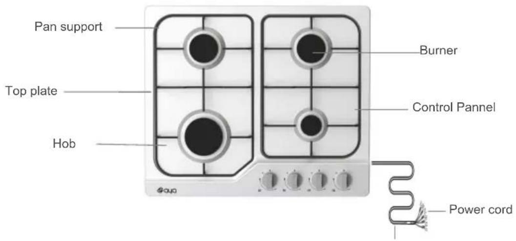
text_image
Pan support Top plate Hob Burner Control Pannel Power cord| Model | ATG4W/5 |
| Pan Support | Enamel |
| Wok pan Support | N/A |
| Top Plate | White |
| Dimension(W*D*H) | 600*510*95 |
| Ignition device | Continuous Ignition Type |
| Gas Connection | G1/2 thread |
| Electric supply | 220-240V~ ,50-60Hz, 2W |
| Burner Feature | Rapid (1), Semi-rapid (2), Auxiliary (1) |
| ΣQn | 7.5kW |
| PIN CODE | 2531DM-0081 |
Accessories
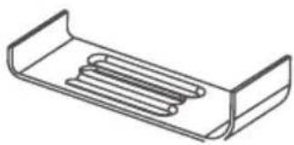
natural_image
Line drawing of a mechanical component with two curved brackets and internal spring-like structures (no text or symbols)Bracket (4)

Sponge (4) Screw (4)

I nj ector (4) Instruction Manual (1)

Gas-pipe bend (1)
How to use the appliance
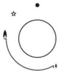
The following symbols will appear on the control panel, next to each control handle :
Black circle: gas off
Large flame: maximum setting
Small flame: minimum setting
natural_image
Simple diagram with a circle, star, and curved arrow (no text or symbols)■ The minimum setting is at the end of the anti-clockwise rotation of the control handle.
■ All operation positions must be selected between the maximum and minimum position.
■ The symbol on the control panel, next to the control handle will indicate which burner it operates.
Automatic ignition with flame failure safety device
The appliance is fitted with a flame failure safety device on each burner, which is designed to stop the flow of gas to the burner head in the event of the flame going out.

Automatic ignition with flame failure safety device
The appliance is fitted with a flame failure safety device on each burner, which is designed to stop the flow of gas to the burner head in the event of the flame going out.
To ignite a burner:
o Press in the control knob of the burner that you wish to light and turn it anti-clockwise to the maximum position.
o If you keep the control knob depressed, the automatic ignition for the burner will operate.
o You should hold down the control knob for 15 seconds after the flame on the burner has lit. If after 15s the burner has not lit, stop operating the device and open the compartment door and/or wait at least 1 min before attempting a further ignition of the burner.
o After this 15-second interval, to regulate the flame you should continue turning the control knob anti-clockwise until the flame is at a suitable level. The operating position MUST be at a position between the maximum and minimum position.
To switch the burner off, turn the control knob fully clockwise to the gas off position.
o In case of power failure, the burners can be lit by carefully using a match.
safety and energy saving advice
- The diameter of the bottom of the pan should correspond to that of the burner.
| BURNERS | PANS | |
| min. | max. | |
| Triple-Crown | 200mm | 240mm |
| Rapid | 200mm | 240mm |
| Semi-Rapid | 160mm | 180mm |
| Auxiliary | 120mm | 160mm |

■ Do not use cookware that overlaps the edge of the burner.
| NO YES | |||
 | Do not use small diameter cookware on large burners.The flame should never come up the sides of the cookware. | Always use cookware that is suitable for each burner,to avoid wasting gas and discolouring the cookware. |  |
 | Avoid cooking without a lid or with the lid half off- as this wastes energy | P lacea lid on thecookware. |  |
 | Do not use a pan with a convex or concave bottom. | Only use pots, saucepans and frying pans with a thick, flat bottom. |  |
 | Do not place cookware on one side of a burner, as it could tip over. | Always place the cookware right over the burners, not to one side. |  |
| Do not use cookware with a large diameter on the burners near the controls, which when placed on the middle of the burner may touch the controls or be so close to them that they increase the temperature in this area and may cause damage. | |||
 | Never place cookware directly on top of the burner. | Place the cookware on top of the trivet. | |
 | Do not place anything, eg. flame tamer, asbestos mat, between pan and pan support as serious damage to the appliance may result. | ||
 | Do not use excessive weight and do not hit the cookwith heavy objects | Handle cookware carefully when they are on the burner. |  |

■ It is not recommended to use roasting pans, frying pans or grill stones heated simultaneously on several burners because the resulting heat build-up may damage the appliance.
■ Do not touch the top plate and trivet whilst in use for a certain period after use.

■ As soon as a liquid starts boiling, turn down the flame so that it will barely keep the liquid simmering.
Cleaning and maintenance

■ Cleaning operations must only be carried out when the appliance is completely cool.
■ The appliance should be disconnected from your mains supply before commencing any cleaning process.
■ Clean the appliance regularly, preferably after each use.
■ Abrasive cleaners or sharp objects will damage the appliance surface; you should clean it using water and a little washing up liquid.
| Usable Unusable | |
 Soft cloth Soft cloth Neutral Detergent Neutral Detergent |  Nylon Brush Nylon Brush  Metal Brush Metal Brush Edible Oil [ST96] Acidic/Alkali Detergent Edible Oil [ST96] Acidic/Alkali Detergent Abrasive Thinnc [W4Z7] Abrasive Thinnc [W4Z7] |
Pan support, Control handles
• Take off the Pan support.
- Clean these and the control handles with a damp cloth, washing up liquid and warm water. For stubborn soiling, soak beforehand.
- Dry everything with a clean soft cloth.
Top plate
- Regularly wipe over the top plate using a soft cloth wellwrung-out in warm water to which a little washing up liquid has been added.
- Dry the top plate thoroughly after cleaning.
- Thoroughly remove salty foods or liquids from the hob as soon as possible to avoid the risk of corrosion.
- Stainless steel parts of the appliance may become discoloured over time. This is normal because of the high temperatures. Each time the appliance is used these parts should be cleaned with a product that is suitable for stainless steel.
BURNERS
- Remove the burner lids and Flame Spreaders by pulling them upwards and away from the top plate.
Soak them in hot water and a little washing up liquiddetergent or
- After cleaning and washing them, wipe and dry them carefully. Make sure that the flame holes are clean and completely dry.
- Wipe the fixed parts of the burner cup with a damp cloth and dry afterwards.
- Gently wipe the ignition device and flame supervision device with a well wrung-out cloth and wipe dry with a clean cloth.
- Before placing the burners back on the top plate, make sure that the injector is not blocked.
- Re-assemble the Auxiliary, Semi-Rapid, Rapid and Triple-Crown burners as follows :

text_image
Exploded view diagram of a mechanical assembly with numbered parts for identification-
Place the flame spreader (4) on to the burner cup (5) so that the ignition device and the flame supervision device extend through their respective holes in the flame spreader. The flame spreader must click into place correctly.
-
Position the burner lid (1, 2, 3) onto the flame spreader (4) so that the retaining pins fit into their respective recesses.

Replace parts in the correct order after cleaning.
- Do not mix up the top and bottom.
- The locating pins must fit exactly into the notches.
Warnings
- Do not modify this appliance.
- This appliance must be installed by an authorised technician or installer.
- Prior to installation, ensure that the local distribution conditions (nature of the gas and gas pressure) and the adjustment of the appliance are compatible.
- The adjustment conditions for this appliance are stated on the label (or data plate).
- This appliance is not connected to a combustion products evacuation device. It should be installed and connected in accordance with current installation regulations. Particular attention should given to the relevant requirements regarding ventilaton.
- Before installing, turn off the gas and electricity supply to the appliance.
- All appliances containing any electrical components must be earthed.
- Ensure that the gas pipe and electrical cable are installed in such a way that they do not touch any parts of the appliance which may become hot.
- Gas pipe or connector shouldn't be bent or blocked by any other appliances.
- Check the dimensions of the appliance as well as the dimensions of the gap to be cut in the kitchen unit.
- The panels located above the work surface, directly next to the appliance, must be made of non-flammable material. Both the stratified surfacing and the glue used to secure it should be heat resistant, to prevent deterioration.
- Turn on appliance tap and light each burners.
- Check for a clear blue flame without yellow tipping. If burners shows any abnormalities check the following:
- Burner lid on correctly
- Flame spreader positioned correctly
- Burner vertically aligned with injector nipple
- A full operational test and a test for possible leakages must be carried out by the fitter after installation.
- The flexible hose shall be fitted in such a way that it cannot come into contact with a moveable part of the housing unit and does not pass through any space susceptible of becoming congested.
-
Grease cranes produced at the factory to meet the requirement of all life hob.
-
These instructions are only valid if the country symbol appears on the appliance. If the symbol does not appear on the appliance, it is necessary to refer to the technical instructions which will provide the necessary instructions concerning modification of the appliance to the conditions of use of the country.
- Prior to installation, ensure that the local distribution conditions (nature of the gas and gas pressure) and the adjustment of the appliance are compatible.
- The adjustment conditions for this appliance are stated on the label (or data plate).
- This appliance is not connected to a combustion products evacuation device. It shall be installed and connected in accordance with current installation regulations. Particular attention shall be given to the relevant requirements regarding ventilation.
- Hob guards cannot be used. The use of inappropriate hob guards can cause accidents.
Installation of the appliance
text_image
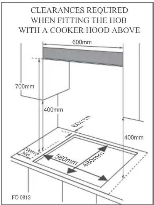
CLEARANCES REQUIRED WHEN FITTING THE HOB WITH A COOKER HOOD ABOVE 600mm 700mm 400mm 60mm 400mm 200mm Min 560mm 480mm FO 0813■ This appliance is to be built into a kitchen unit or 600 mm worktop, providing the following minimum distances are allowed;
- The edges of the hob must be a minimum distance of _0 from a side or rear wall.
-700 mm between the highest point of the hob surface (including the burners) and the underside of any horizontal surface directly above it. - 400 mm between the hob surfaces, providing that the underside of the horizontal surface is in line with the outer edge of the hob. If the underside of the horizontal surface is lower than 400 mm, then it must be at least 50 mm away from the outer edges of the hob.
- 50 mm clearance around the appliance and between the hob surface and any combustible materials.
- You must have a gap of at least 25 mm and at most 74 mm between the underneath of the appliance and any surface that is below it.

text_image
25 mm (MIN.) 45 mm- An oven must have forced ventilation to install a hob above it.
- Check the dimensions of the oven in the installation manual.
-
The cut out size must obey the indication.
-
Remove the pan supports, the burner lid and flame spreader and carefully turn the appliance upside down and place it on a cushioned mat.
Take care that the Ignition devices and flame supervision devices are not damaged in this operation.
-
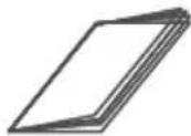
Apply the sponge provided around the edge of the appliance.
-
Do not leave a gap in the sealing agent or overlap the thickness.

natural_image
Simple line drawing of a hand holding a pen above a laptop with a cross mark, no text or symbols present.
Do not use a silicon sealant to seal the appliance against the aperture.
This will make it difficult to remove the appliance from the aperture in future, particularly if it needs to be serviced.
text_image
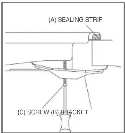
(A) SEALING STRIP (C) SCREW (B) BRACKET- Place the bracket(B) over the holes that match the size of the screws. There are one set of screw holes in each corner of the hob(H).
Slightly tighten a screw(C) through the bracket(B) so that the bracket is attached to the hob, but so that you can still adjust the position.
-
Carefully turn the hob back over and then gently lower it into the aperture hole that you have cut out.
-
On the underneath of the hob, adjust the brackets into a position that is suitable for your worktop.
Then fully tighten the screws(C) to secure the hob into position.

■ This appliance must be installed and connected in accordance with installation regulations in force in the country in which the appliance is to be used.
■ This appliance is supplied to run on LPG and natural gas. Conversion for use on LPG and natural gases must only be undertaken by a qualified person.
Gas supply replacement and installation guidelines:
LPG > NG
NG > LPG
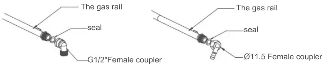
text_image
The gas rail seal G1/2"Female coupler The gas rail seal Ø11.5 Female coupler- It is the law that all gas appliances are installed by competent persons in accordance with the current edition of the Gas Safety Installation and Use Regulations.
- It is in your interest and that of safety to ensure compliance with the law.
- In the UK, GASSAFE registered installers work to safe standards of practice. The hob must also be installed in accordance with the current edition of BS 6172. Failure to install the cooker correctly could invalidate the warranty, liability claims and lead to prosecution.
Gas category, gas type and destination country (for all models)
Gas specification
| Model No. | Gas type & pressure | Electrical power | Heat input and orifice size marked(mm) | Total Heat input | |||
| Work burner | Rapid burner | Semi-rapid | Auxiliary-rapid | ||||
| ATG4W/5 | 220-240V~50-60Hz | / | 3.0kW(219g/h) | 1.75kW(127g/h) | 1.0kW(73g/h) | 7.5kW(546g/h) | |
| G30 29mbar | / | 0.87 0.66 | 0.50 | NA | |||
| G20 20mbar | / | 1.30 0.78 | 1.00 | ||||
electrical connection
■ This appliance must be earthed.
■ This appliance is designed to be connected to a 220-240V\~ ,50-60Hz electricity supply.
■ The wires in the mains lead are coloured in accordance with the following code ;
- Green/yellow = Earth
- Blue = Neutral
- Brown = Live

■ The wire which is coloured green and yellow must be connected to the terminal which is marked with the letter E or by the earth symbol.
Gas conversion

■ Take precautions on the operations and adjustments to be carried out when converting from one gas to another.
■ All work must be carried out by a qualified technician.
■ Before you begin, turn off the gas and electricity supply to the appliance.
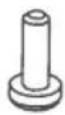
1 Change the injector of the burners.
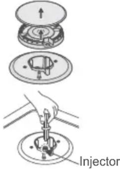
text_image
InjectorRemove the pan support, Burner lid and Flame spreader.
Unscrew the injector using a 7mm box spanner and replace it with the stipulated injector for new gas supply. Carefully reassemble the all components.
After injectors are replaced, it is advisable to strongly tighten
Adjustment of minimum level of the flame
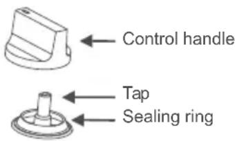
text_image
Control handle Tap Sealing ring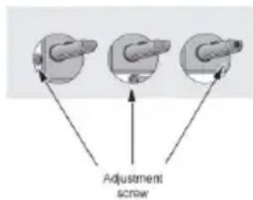
text_image
Adjustment screw① Turn the taps down to minimum
② RRemove the knob from the tap and place a small bladed screwdriver in the centre of the tap shaft.
③ The correct adjustment is obtained when the flame has a length of about 3 - 4 mm.
- For butane/propane gas, the adjusting screw must be tightly screwed in.
- Refit the control knob.
- Make sure that the flame does not go out by quickly turning from maximum flow to minimum flow. If it does then remove the control knob and make further adjustments to the gas flow, testing it again once the adjustment has been made.
④ Repeat this process for each one of the gas taps.

■ Do not dismantle the tap shaft : in the event of a malfunction, change the whole tap.
■Before placing the burners back on the top place, make sure that the injector is not blocked.
■ A full operational test and a test for possible leakages must be carried out after gas conversion. (such as soap water or gas detector)
■ After completing conversion, a qualified technician or installer has to mark "V" on the right gas category to match with the setting in rating plate. Remove the previous setting "V" mark.
Trouble shooting
- Repairs should be performed by a licensed technician only. Improper repair may result in considerable danger to you and others.
• However, some minor problems can be resolved as follows :
| Problem Probable cause Solution | ||
| Not ignited | No Spark. Check the electricity supply | . |
| The burner lid is badly assembled. | Assemble the lid correctly. | |
| The gas supply is closed. Open the gas supply completely. | ||
| Badly ignited | The gas supply is not completely open. | Open the gas supply completely. |
| The burner lid is badly assembled. | Assemble the lid correctly. | |
| The ignition plug is contaminated with alien substance. | Wipe alien substance with a dry cloth . | |
| The burners are wet. Dry the burners lids carefully. | ||
| The holes in the flame spreader are clogged. | Clean the flame spreader. | |
| Noise made when combusted and ignited | The burner lid is badly assembled. | Assemble the burner lid correctly. |
| Flame goes out when in use. | The flame supervision device is contaminated with alien substance. | Clean the flame supervision device. |
| Product being cooked has boiled over and extinguished the flame. | Turn off burner knob. Waitone minute and reignite zone. | |
| A strong draught may have blown the flame out . | Please turn off zone and check cooking area for draught such as open windows. Waitone minute and reignite zone | |
| Yellow Flame | The holes in the flame spreader are clogged. | Clean the flame spreader. |
| Different gas is used. Check the gas used. | ||
| Unstable Flame | The burner lid is badly assembled. | Assemble the burner lid correctly. |
| Gas Smell | Gas leakage | Stop using the product and close the middle valve.Open the window to ventilate.Contact our service centre by using a phone outside. |

■ If problem is not solved, please contact customer care centre.
We decline liability for any damage or accident derived from any use of this product which is not in conformity with the instructions contained in this booklet
| CORRECT DISPOSAL OF THIS PRODUCT | |
 | This marking indicates that this product should not be disposed with other household wastes throughout the EU. To prevent possible harm to the environment or human health from uncontrolled waste disposal, recycle it responsibly to promote the sustainable reuse of material resources. To return your used device, please use the return and collection systems or contact the retailer where the product was purchased. They can take this product for environmental safe recycling. Please bring the batteries in the batteries disposal center (contact your retailer in order to protect the environment). |
In accordance with Article L. 217 of the Consumer Code, your product benefits from a legal guarantee of conformity of 2 years.
To contact our After-Sales Service, before going to your BUT store, call 09 78 97 97 97,
From Monday to Saturday from 8:00 am to 8:00 pm (local call price).

LE TRI

FACILE