Antmix 24FX USB - Mixer ANT - Free user manual and instructions
Find the device manual for free Antmix 24FX USB ANT in PDF.

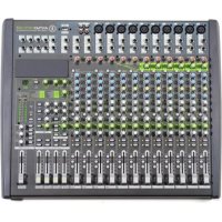
| Product type | Analog mixing console with USB interface and digital effects processor |
| Brand | ANT |
| Model | Antmix 24FX USB |
| Number of channels | 24 input channels (16 mono, 4 stereo, 2 additional stereo) |
| Microphone inputs | 16 balanced XLR inputs with +48V phantom power |
| Line inputs | 16 balanced 6.35 mm jack inputs (mono) + 6 stereo jack pairs (4+2) |
| Main outputs | 2 x balanced XLR, 2 x unbalanced 6.35 mm jack |
| Auxiliary outputs | 4 AUX sends (balanced 6.35 mm jack) |
| Group outputs | 4 group outputs (unbalanced 6.35 mm jack) |
| USB interface | USB type B port for bidirectional audio recording/playback |
| Effects processor | Internal DSP with 100 effects (echo, reverb, chorus, flanger, etc.) |
| Equalizer | 3-band semi-parametric on mono channels (with adjustable frequency), 4-band on stereo channels |
| Compressor | Built-in on the first 8 mono channels (adjustable threshold and ratio) |
| Low-cut filter | 75 Hz high-pass filter on all channels |
| Stereo returns | 4 stereo returns (6.35 mm jack) |
| Headphone output | 2 headphone outputs (6.35 mm stereo jack) with independent volume |
| Control room output | 1 CONTROL ROOM output (balanced jack) with dedicated volume |
| Phantom power | +48V globally switchable |
| Mains power supply | 100-240 V AC, 50/60 Hz, 70 W max |
| Dimensions (W x D x H) | 508 x 408 x 85 mm |
| Weight | Approximately 8.5 kg |
| Chassis material | Sturdy metal with ABS side panels and integrated handles |
Frequently Asked Questions - Antmix 24FX USB ANT
User questions about Antmix 24FX USB ANT
0 question about this device. Answer the ones you know or ask your own.
Ask a new question about this device
Download the instructions for your Mixer in PDF format for free! Find your manual Antmix 24FX USB - ANT and take your electronic device back in hand. On this page are published all the documents necessary for the use of your device. Antmix 24FX USB by ANT.
USER MANUAL Antmix 24FX USB ANT
- 1 x Mixing console
• 1 x Mains cable with VDE plug
• 1x User manual - Section 1
• 1x User manual - Section 2
The warnings in this manual must be observed together with the "user manual - Section 2".
1 | INTRODUCTION
Thank you for choosing a A.N.T - Advanced Native Technologies - product
In ANTMIX series of mixing consoles we have put our pass-on and our technological background gained over the years, to offer products that meet your needs, and maintaining the quality over time.
All the models of this series represent a solution rich of features and optimally blend professional features with great quality and exceptional value as: the advanced internal DSP with different effects and variations, the built-in compressor for main microphone inputs, 60 mm faders as well as a series of I/O to Lfill a wide range of applications.
Both models feature a USB port, allowing connections to a computer or a tablet
Specifically designed for an immediate and user-friendly use, these mixers satisfy the needs of those who want an audio mixer providing excellent performances, wise versatility of connections and controls as well as the best value for this range of products. Please dedicate some minutes to read this instruction manual in order to quickly achieve the best performances from this product. For safety precautions, warranty and disposal please refer to attached Section 2.
For further information about all A.N.T products catalog, please visit our website www.ant-intomusic.com
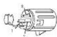
2 | INSTALLATION
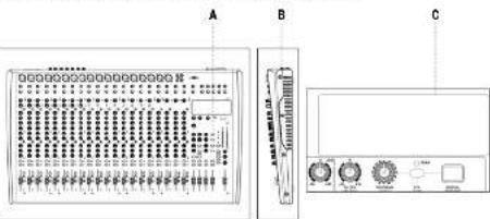
ANTMIX 16FX USB / 24FX USB models
are provided of
A | Metal rough and light chassis.
B | ABS side panels with
ergonomic handle
C | Front panels holes for optional boards
-MEX 1524 (ME3 player) or
31X1524(Bluetooth® module)
3 | DESCRIPTION
3.1 MIXER CONTROLS & CONNECTIONS
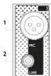
3.1.1 | MONO/STEREO INPUTS
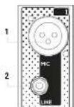
1 MIC INPUT
XLH-F balanced microphone input.
2 MONO LINE INPUT - CHANNELS FROM 1 TO 8 (16FX USB) / FROM 1 TO 16 (24FX USB) 5.35 mm. (1/4") balanced line input. You may also use an unbalanced cable.
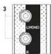
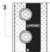
3 STEREO LINE INPUT - CHANNELS FROM 9 TO 12 (16FX USB) / FROM 17 TO 20 (24FX USB) Two 6.35 mm (1/4') balanced line input.
Connecting only one cable to L/MONO, it becomes a mono channel. You can also use an unbalanced cable.
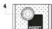
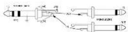
4 INSERT - CHANNELS FROM 1 TO 8 (16FX USB) / FROM 1 TO 16 (24FX USB)
6.35 mm, (1/4") TRS socket. This socket allows you to connect external devices (e.g. a compressor, an EQ, etc.) to process the signal. For this connection use a "Y" cable, plugging to this socket a TRS connector (tip = send, ring = return, and sleeve = ground) then connect the external device with two TS connectors, one for input and one for the output.
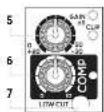
5 GAIN & CLIP LED
This knob adjusts the gain of the microphone or line signal, turn it to the right to raise the level or to the left to decrease it.
The CLIP ED is at when the input signal is too high
6 COMP & LED - CHANNELS FROM 1 TO 6 (16FX USB) / FROM 1 TO 8 (24FX USB)
This knob simultaneously adjusts compression on threshold and ratio. Turning the knob hard left, the compressor is turned off, turning to the right you activate it, until the maximum compression is +10. Use this control for example, to make voices levels more homogeneous. The LED next to the knob lights up when the compressor is activated.
7 LOW CUT - CHANNELS FROM 1 TO 12 (16FX USB) / FROM 1 TO 20 (24FX USB)
This switch activates the hi-pass filter to reduce the frequencies from 75Hz down. Use it to avoid that microphones connected to the input channels will pick up unwanted signals rich of low frequencies.
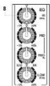
8 EQ - CHANNELS FROM 1 TO 8 (16FX USB) / FROM 1 TO 16 (24FX USB)
Use this three-band equalizer to boost or to cut the high, mid and low frequencies to get the best mix in any environment. The semi-parametric FREQ control allows frequency selection from 100Hz to 5kHz.

9
10
-
-
-
-
-
-
-
-
-
-
-
-
-
-
-
-
-
-
-
-
-
-
-
-
-
-
-
-
-
-
-
-
-
-
-
-
-
-
-
-
-
-
-
-
-
-
-
-
-
-
-
-
-
-
-
-
-
-
-
-
-
-
-
-
-
-
-
-
-
-
-
-
-
-
-
-
-
-
-
-
-
-
-
-
-
-
-
-
-
-
-
-
-
-
-
-
-
-
- 99.
-
-
-
-
-
-
-
-
-
-
-
-
-
-
-
-
-
-
-
-
-
-
-
-
-
-
-
-
-
-
-
-
-
-
-
-
-
-
-
-
-
-
-
-
-
-
-
-
-
-
-
-
-
-
-
-
-
-
-
-
-
-
-
-
-
-
-
-
-
-
-
-
-
-
-
-
-
-
-
-
-
-
-
-
-
-
-
-
-
-
-
-
-
-
-
-
11
12
。
13

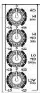
9 EQ - CHANNELS FROM 9 TO 12 (16FX USB) / FROM 17 TO 20 (24FX USB)
Use this four-band equalizer to boost or to cut the high, mid and low frequencies to get the best mix in any environment.
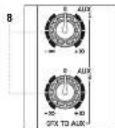
10 AUX 1 & 2
These knobs adjust the signal sent to AUX SEND 1 and 2, both sends can be set pre/post faster.
11 AUX 1 & 2 PRE/POST
This selection determines whether the AUX 1 and 2 send level is independent (PFE) or is influenced (POST) by the channel level control. Generally it is used PFE to send the signal to stage monitors or IEM. POST to send the signal to an external effect unit.
12 AUX 3
This post-lader send, i.e. dependent on level control of its channel, allowing to adjust the signal sent to an external effect unit or to a monitor connected to the AUX SEND 3 output.
13 DFX POST
This send, influenced by the individual channel level control, adjusts the signal sent to the internal effects or to an external effects connected to DFX SEND output. Furthermore, the DFX POST control can be used as the fourth auxiliary send (deactivating the internal effect via the DFX MUTL button) for connection to an external effects unit connected to the AUX SEND 4 output.
14 PAN - CHANNELS FROM 1 TO 8 (16FX USB) / FROM 1 TO 16 (24FX USB)
This knob adjusts the signal position in the stereo field.
14

15

16
17
1.
[Non-Text]
18
19
1
20
21
[Non-Text]
22
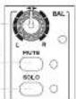
15 BAL - CHANNELS FROM 9 TO 12 (16FX USB) / FROM 17 TO 20 (24FX USB)
The BAL knob sets the left-right balance for stereo channels.
16 MUTE & LED
Press this button to mute the selected channel source.
The lit LED indicates the MUTE activation.
17 SOLO & LED
Press this button to check channel signal level before the fader.
It works also when the channel is muted, the led indicates the activation of the command.
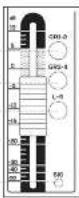
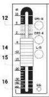
18 GR 1-2
Press this button to route the channel signal to GROUP CUT 1-2 outputs
19 GR 3-4
Press this button to route the channel signal to GROUP CUT 3.4 outputs
20 L-R
Press this button to route the channel signal to MAIN MIX L-R outputs.
21 VOLUME
Use this fader to adjust overall channel volume.
22 SIG LED
This led is light when the input: signal is very strong and it's close to distortion.
If the LLD is continuously lit, you need to reduce the VOLUME of the fader or cut the channel LC by reducing the boost introduced by the HI-MID-LOW tone gains.
3.1.2 | STEREO INPUTS
13/14 - 15/16 (ANTMIX 16FX USB) / 21/22 - 23/24 (ANTMIX 24FX USB)
1
2

3
5
9
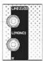
1 LINE L (MONO) & R INPUT
Two 6.35 mm (1/4") balanced line input.
Connecting only one cable to L/MONO, it becomes a mono channel. You can also use an unbalanced cable.
2 GAIN & CLIP LED
This knob adjusts the gain of the microphone or line signal, turn it to the right to raise the level or to the left to decrease it.
The CLIP ED is at when the input signal is too high
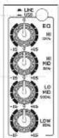
3 LINE/USB
Press this switch to assign channels 75/16 (16FX USB) and 23/24 (24FX USB) to the USB interface and receive the audio signal from the computer connected to the unit. In the LINE position, key releases, the channels are normally assigned to the respective inputs jack
4 EQ
Use this four-band equalizer to boost or to cut the high, mic and to frequencies to get the best mix in any environment.
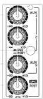
5 AUX 1 & 2
These knobs adjust the signal sent to AUX SEND 1 and 2. Both sends can be set pre-/post-fader.
6 AUX 1 & 2 PRE/POST
This selector determines whether the AUX 1and 2 sand level is independent (PRE) or is influenced (POST) by the channel level control. Generally it is used PRE to send the signal to stage monitors on EM, POST to send the signal to an external effect unit.
7 AUX 3
This post, lader send, i.e. dependent on level control of its channel, allowing to adjust the signal sent to an external effect unit or to a monitor connected to the AUX SEND 3 output
B DFX POST
This send, influenced by the individual channel level control adjusts the signal sent to the internal effects or to an external effects connected to DIFX SEND output - furthermore, the DIFX POST control can be used as the fourth auxiliary send (deactivating the internal effect via the DIFX MUTE button) for connection to an external effects unit connected to the AUX SEND 4 output
9 BAL
The BAL knob sets the left right balance for stereo channels.
10 MUTE & LED
Press this button to mute the selected channel source.
The lit LED indicates the MUTF activation.
11 SOLO & LED
Press this button to check channel signal level before the fader.
It works also when the channel is muted; the led indicates the activation of the command.

12 GR 1-2
Press this button to route the channel signal to GROUP CUT 1-2 outputs.
13 GR 3-4
Press this button to route the channel signal to GROUP CUT 3-4 outputs
14 L-R
Press this button to route the channel signal to MAIN MIX L-R outputs.
15 VOLUME
Use this lader to adjust overall channel volume.
16 SIG LED
This led is light when the input signal is very strong and it's close to distortion.
If the LED is continuously ill, you need to reduce the VOLUME of the fade or cut the channel EQ by reducing the boost introduced by the HI MID LOW tone gains.
3.1.3 POWER SUPPLY AND MASTER SECTION
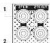
1 2-TRACK IN
Unbalanced line input with RCA L/R sockets.
Connect to this socket the output of a hi-fi equipment (CD) or other device with RCA outputs.
2 2-TRACK OUT
Unbalanced line output with RCA L/R sockets.
Connect these outputs to a h-fi device, e.g. a recorder; the volume is set by MAIN MIX output.
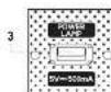
3 POWER LAMP
USB socket to power a lamp with a voltage of 5V - 500mA
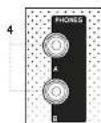
4 PHONES
Output for connection to two headphones (A & E) with 6,35mm. (1/4") stereo jack.
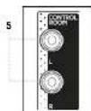
5 CTRL/R
CONTROL ROOM output with two 6.35 mm (1/4" line sockets
This output section collects the signal from the CTRL ROOM SOURCE section. In studio applications the typical use is for studio monitors but can also be used to drive a second group of powered speakers with level control independent from the master, thus creating two distinct listening areas at different volumes. The volume of this output is adjusted using the CTRL / ROOM knob regardless of the MAIN MIX output levels
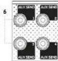
6 AUX SENDS 1, 2, 3 AND 4
5.35 mm. (1/4") output socket of relevant Aux sends 1, 2, 3 and 4.
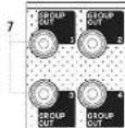
7 GROUP OUTS 1, 2, 3 AND 4
Outputs of the respective groups on a 6.35 mm (1/4") balanced jack. These outputs allow to drive a second group of amp-fied audio-seakers with level control independent from the master, thus creating more distinct listening areas with different volumes or directing the selected signals to a recorder / sound card.
8 DFX TO AUX 1 / AUX 2
These knobs set the signal level of the internal effects unit for AUX 1 and 2 sends.
Use them to increase or decrease the amount of processed signal.
9 TO DFX ST. OUT
This knob allows you to send the output of the internal effects unit to rear panel dedicated output DFX'S OUT. Connect this output to your external effects units if any. The output signal is the sum determined by the DFX sends for each channel.
10 PROGRAM (PUSH)
This 100 position selector allows you to choose the
type of effect.
Turn the knob until you reach the desired program.
then press the knob to activate the selected effect
The first 10 programs called ECHO reproduce the classic echo effect with increasing delay in the subsequent variants, ECHO + VERE algorithms simulate a combination of echo and reverb. The impressive effect used in many musical productions, the TREMOLO effects are mostly used on stringed instruments, while PLATE, CHIDRUS, and VOCAL programs offer a pleasant sound widening and are able to strengthen vocals. The ROTARY effects simulate leave organ while the SMALL BOOK programs reproduce the reverberation of rooms with similar dimensions to those of residential rooms, alternating the simulation of reflective and absorbent walls. The FLANGUR + FLY section represents a combination of effects perfect for different instruments, in particular keyboards, and finally the LARGE HALL effects package simulate the reverberation of environments with large volumes characterized by mostly reflecting, naked walls.
11 DFX DISPLAY
This display shows the numbers corresponding to selected effects by the PROGRAM (PUSH) encoder.
12 PEAK
This LED is lit when the signal sent to DFX is too high, and there's a risk to saturate the internal effect. It's a good setting of the effect sends when the LED flashes occasionally only on signal peaks. When the LED remains continuously lit, it is an indication of saturation. In that case please cut the volume of DFX POST channel sends.
13 DFX MUTE
This button allows you to enable or disable the return signal of the internal effects unit.

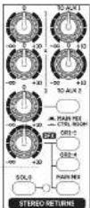
14 STEREO RETURNS 1-2-3-DFX
Master level controls for the auxiliary STEREO RETURNS:
- 1: Controls STEREO RETURN level sent to the MAIN MIX output
- 2. Controls STEREO RETURN 2 level sent to the MAIN MIX output
- 3. Controls STEREO RETURN 3 level assignable, by the MAIN MIX/CRTL ROOM key to the MAIN MIX output or to the CONTROL ROOM outputs
- DFX Controls DFX OUT level and the STEREO RETURN 4 assignable, by the 3 lateral keys, to groups I-2 (GH I-2), groups 3-4 (GR 3-4) and MAIN MIX output. By pressing the STEREO RETURN SOLO button (with LED) all STEREO FETLRNS enter SOLO mode and their mixed signal is sent to the CONTROL ROOM and to PHONES A B outputs
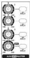
15 AUX/DFX MASTER & SOLO
Controls the master level of the respective auxiliary sends and the DFX send (internal effect). Press the SOLO button to pre-listen sends 1-4, their signal is sent to the CTRL ROOM and PHONES A-B outputs.
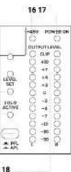
16 +48V
This LED is lit to when Phantom 45V is acted
17 POWER ON
This LED is lit green when the mixer is ON.
18 OUTPUT LEVEL
MAINIX output level LED indicators. The L indicator can also work to control the level in SDLG. When the CLIP LED lights up, the output signal level is too high.
19 LED LEVEL SET
When this LED is on, the OUTPUT LEVEL LED bar indicates the input level of the channel in SOLO PFL mode, level can be optimized by the GAIN control of the selected channel.
20 LED SOLO ACTIVE
When it's it, one or more channels and/or one or more auxiliary aux sends are selected in SOLO mode.
21 PFL/AFL BUTTON
It allows the choice between two types of SOLO for the CTRL ROOM and PHONES A B outputs. When it is released (PFL = "pre-fader listening"), you can listen to the audio signal before the faster. This mode is useful to check the input level of the channel in SOLO via the main LED meter, and optimizing the gain accordingly. When it is pressed (AFL = "after-fader listening"), it is possible to hear the microq of channel(s) and the relevant AUX auxiliary sends placed in SOLO, keeping current levels and pans adjustments.
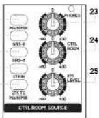
22 MAIN MIX / GR 1-2 / GR 3-4 / 2 TK IN.
Press the key(s) of the signal(s) you wish to listen via the CONTROL ROOM
23 PHONES
This knob controls the volume of the headphones connected to the PHONES A-B outputs.
24 CTRL ROOM
This knob controls the level of the CONTROL ROOM outputs (eg pair of studic monitors).
25 2TK LEVEL
Level control of 2TK-IN stereo input (RCA connectors) or from optional Bluetooth cards or USB player)
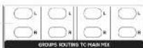
26 L & R GROUPS ROUTING TO MAIN MIX
Press the L and R buttons to assign the group signal to the MAIN MIX output
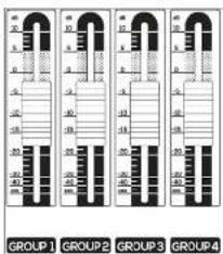
27 GROUP OUT 1-4
These faders independently adjust the output level of the four groups, which can be used both as master levels for recording and to drive other powered speakers to create distinct listening areas at different volumes.
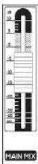
28 MAIN MIX
Adjust this fader to set MAIN MIX OUTPUT level
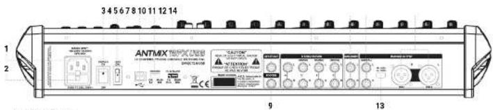
1 MAINS INPUT
Plug into this socket the mains cord supplied with the unit. Make sure the unit is Lirmed OFF before connecting the cable to the mains. For your safety, never disconnect the earth lead.
2 FUSE
Protection fuse. WARNING Replace the fuse only with one of the same type and with the same value if the fuse blows repeatedly, contact an authorized service center.
3 POWER ON/OFF
Press this switch to turn ON or OFF the unit
4 +48V
This switch allows you to turn ON or OFF the phantom power for condenser microphones. ON = Switch turned ON (depressed to the top). +48V LED lit. OFF = Switch turned OFF. +48V LED turned off.
5 USB PORT
This type B USB port allows connection to a computer or other audio device with a USB interface.
6 RECORD
This selector allows you to choose the signal to send to the device connected to the USB port. Set it to MAIN MIX when you want to record the signal assigned to that stereo or to GB 1-2 when you want to record the signal assigned to that stereo group.
7 PLAYBACK
Use this selector to choose the signs you want to read from the device connected to the USB port. Set it's switch to MAIN MIX to send the audio signal coming from the computer (or from the connected audio device) directly to the MAIN MIX outputs or to CH 15-6 (ANTMX 16FX USB), /CH 23-24 (ANTMX 24-X USB) to assign it to the above mentioned channels. NOTE: If you assign the USB audio signal to channels 15-16 / 23-24, listen to the LINL /USB switch (3) on the front panel and choose USB. NOTE: To avoid digital caps when overdusting, assign the RECORD switch to GF1.2 and the PLYSACK selector on the storage channel 15-16 / CH 23-24 assigning it only to GF3.4 or MAIN MIX.
8 DFX ST OUT
The signal from the internal effects processor is present in this balanced stereo output, 6.35mm jack
9 FOOTSW.
Connect an external pedal to this unbalanced jack for inserting or excluding internal effects. Press once to deactivate the effects (DFX MUTE function), press a second time to reactivate them
10 STEREO RETURN(S)
Connect to these input jacks the return of an external effects unit or other stereo or mono device. For each STERLO RETURN auxiliary return (1-2-3-4) there are two audio inputs - L (MONO)/R - on 6.35mm balanced jack connectors
11 MAIN INSERT
6.35mm jack sockets for insertion of external processors (eg EQ or compressors) in the MAIN circuit, the tip of the jack sends the signal to the processor, the ring receives the processed signal, while the sleeve has the signal of both grounds
12 MAIN MIX OUT
6.35mm unbalanced jack outputs. Connect the inputs of your amplification system or master recorder to these outputs.
13 +4dBU/-30dBU
This selector allows you to select the output level between 14 dBu and -30 dBu to optimize the connection for any destination.
14 MAIN MIX OUTPUT
Balanced XLR-M outputs. Connect the inputs of your amplification system or master recorder to these outputs.
3.1.4 | USB INTERFACE & APPLICATIONS
1 RECORD
Select the source for recording between GRI-2 and MAIN MIX. MAIN MIX is ideal for recording a live session or basic tracks (rhythm or other) while during overdubbing it is advisable to record from GRI 2 and use MAIN MIX for direct listening. NOTE: to avoid annoying loops, never choose MAIN MIX when playback is on MAIN MIX. Do not mute the GRI-2 signal to MAIN MIX.
2 PLAYBACK
Allows you to select the USB port signal. During playback and/or overduds, it is advisable to listen via CH15-16 (23-24) both to give the right level to each AUX that equalize MAIN MIX is ideal for audience listening and for the final mixing. NOTE: If you desire to listen to the USB port signal, besides setting this switch to CH15-16 (CH23-24) you have to press the USB key of the relative stereo channel of the mixer.
APPLICATION
Playback
Set the selector to PLAYBACK on CH15-16 (or CH23-24) and press the USB key of the last stereo channel (15-16 or 23-24) to listen to the playback tracks signals from PC/label. In this way you can adjust signals for monitors and musicians, via AUX1 and 2 independently of the MAIN MIX levels (possibly also AUX 3 but remember that it is post-fader) and equalize the signal.
Karaoke
Set the selector to PLAYBACK on CH15 16 (or CH23 24) and press the USB key of the last sleeve channel (16 16 or 23-24) to listen to the playback tracks signals from PC/tablet. In this way you can adjust signals for monitors and musicians, via AUX1 and 2 independently of the MAIN MIX levels (possibly also AUX 3 but remember that it is post-lader) and equalize the signal.
Recording
Set RECORD to MAIN MIX, and assign the channel's you want to record to the L-R output and adjust the volumes. Assign the signals you do not want to record to GR3-4 and adjust the signal for the headphones of the musicians via the AUX sends.
Overdub
Set the RECORD selector to CR1-2, and assign the channels you want to record to the CR1-2 output and adjust the volumes. For listening, pull PLAYBACK on CH15 16 or CH23 24 and press the USB key of the last stereo channel (15 16 or 23 24) to listen to PC/tablet playback tracks. Adjust the signal for the musicians' headphones via the AUX I, 2 and 3 sends (there is no risk of feedback in the headphones). Assign the goal you do not want to record to GF3-4 and adjust the signal for musicians' headphones via the AUX sends.
Mixing
You can make an ITB mix and listen either through the last stereo channel by setting PLAYBACK on 0115-16 (28-24). In this way you can do minimal EQ adjustments. Otherwise you can set the PLAYBACK on MAIN MIX to listen with no action except volume adjustment.

3.1.5 | OPTIONAL BLUETOOTH® & MP3 PLAYER BOARDS 4 | TROUBLESHOOTING
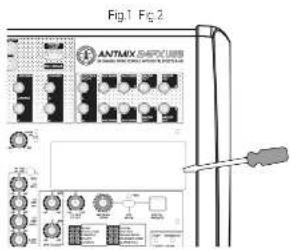
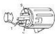
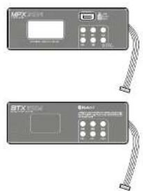
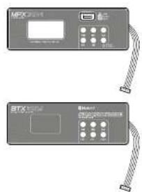
BOARDS INSTALLATION
The installation is very simple, but if you have no experiences, contact a specialized service center. WARNING: For your safety openense turning off the mixer and uncupging the appliance from the mains socket. With a flat-hooded screwdriver, pressgenally under the plastic cover and pry up the right side to removeit carefully. (Fig. 1) To install the optional M-PX 1824 or BIX 1824 card, connect the 5-pin connector cable to the respective 5-pin connector on the printed circuit board of the mixer. (Fig. 2). At this point it is sufficient to hook the optional module in the appropriate housing and take advantage of the new functions.
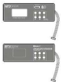
BLUETOOTH® MODULE - BTX 1624
Activate the Bluetooth® interface of your device and press the PAIR button of the board. The source device should recognize the board as BT 4.0 and synthesize automatically. In the mixer, press the 21K IC MAIN MIX selector, then gradually raise the 21K LEVEL knob and the MAIN MIX faster until you reach the desired volume. You can also control the volume from the Bluetooth® card itself, using the VOL- and VOL+ keys, using the I<<▶▶▶▶▶▶▶▶▶▶▶▶▶▶▶▶▶▶▶▶▶▶▶▶▶▶▶▶▶▶▶▶▶▶▶▶▶▶▶▶▶▶▶▶▶▶▶▶▶▶▶▶▶▶▶▶▶▶▶▶▶▶▶▶▶▶▶▶▶▶▶▶▶▶▶▶▶▶▶▶▶▶▶▶▶▶▶▶▶▶▶▶▶▶▶▶▶▶▶▶>
MP3 PLAYER MODULE - MPX 1624
In a USB stick, load all the tracks you want (up to 32Gb), even in multiple folders. Insert: the stick into the USB port of the optional board by simply pressing the PUSH & HOLD button for 2 seconds to start playing the ladder from the first track. The display will alternately show the number of the file and its folder.
To listen to the previous song just press, while to listen to following track press, holding down the keys you can change the folder. The key pause or resume the song, if you press stop, playback will be totally stopped. If you press more times the play, you can choose random play, a single song play or all tracks play.
In the mixer, please press the 2TK TO MAIN MIX selector, then gradually raise the 2TK (PVE) knob and the MAIN MIX fader until you reach the desired listening volume.
| PROBLEM LED SOLUTION | ||
| No sound or very low sound level | Power LED turned off | Make sure the device is properly connected to the main node |
| Power LED turned on, but MAIN MIX over. Raise MAIN MIX level. | ||
| Power LED turned on MAXIFP VCI raised, put MOI + button expressed | Raise MAIN Button | |
| Power LED turned on MAXIFP VCI raised, put input channel I-VCH low | Check connections between sources and mixer. Raise channel I-VCH. | |
| Power LED turned on MAXIFP VCI raised, I-VCH low, put I-VCH off | Arbacter 148V power for microphones according to | |
| Power LED turned on MAIN MIX raised but signal address to OT1-2 or GT3-4 are not addition to MAIN MIX | Press the L-R button over OT1, OT2, OT3 and/or OT4 sides | |
| No effects heard | DTX-MUTC output | Turn off the DTX-MUTC button, and check send levels of all the channels |
| DTX-MUTC decirracted | Check the levels of DTX MCT/UN as well as OT1-2, OT3-4 and MAIN MIX assign buttons. | |
| No Ks signal in monitors | 0-4 MHz decirracted Check CLK IC AUX Low 0-4, 10 MHz nodes levels | |
| Distance THK THIN | Resource the level of the inputs and/or MAIN MIX. Check you have it connected a line signal into MAIN socket. | |
| Certified source | Make sure you have an simultaneously active, more sound sources in the same channel | |
| Check if you activated microphones LOW OUT line | ||
| Check that LINE/AUX accessors of the store channel (In 1A (ANIMIX) In+4 (ONI) or 72.74AM, MIX 74KB-100K) is pressed and that PLR/RACK selector is addressed to desired output (MAIN or OT1-2) | ||
| Recorded signal in no hand | Check that LINE/USD as extra is of the store channel (In 1A (ANIMIX) In+4 (ONI) or 72.74AM, MIX 74KB-100K) is pressed and that PLR/RACK selector is addressed to desired output (MAIN or OT1-2) | |
| No recording | Check that 71 AVPACK selector is addressed to control output (NAI or OT1-2) and that desired synlare addressed to the right destination. | |
| Loop in recording | LINK/SATM storage channel (In 1G (ANIMIX) In+4, LSR) or 72.74° (ANIMIX) PWR, USB) is powered and the EV AnbACK selector is addressed to the wrong output (MAIN or OT1-2) | |

5 | TECHNICAL SPECIFICATIONS
| ANTMIX 16FX USB ANTMIX 124FX USB | ||
| Mono microphone/line input B is win-compressor, B is with compressor | ||
| Stereo microphone/line input C 2 | ||
| Stereo line input 2 3 | ||
| Tower supply 100 Φ/90K 40 Π/100 Φ/40 | ||
| Power attenuation 50Hz max -70Hz max | ||
| Dimensions (kg x H x D) | 510 x 460 x 85 mm20.76 x 18.17 x 33.46" | 735 x 460 x 85 mm22 x 18.17 x 33.46" |
| Weight 70kg - 15.42 lbs 5.70kg - 21.36 lbs | ||
| Microphone input | ||
| Connector XLF-F balanced | ||
| Impedance 1.8kΩ | ||
| Frequency response 20-20kHz +/-1dB | ||
| Distortion (THD = N) =0.03% @ +DD 22-22 kJ A-weighted | ||
| Gain | 0~5dB | |
| Max input | +16dB (balanced) | |
| Low-out | 75Hz 12dB/Hz | |
| Signal to noise tone | x 100 dB A weighted | |
| Function powering | +40V | |
| Line Input | ||
| Connector x20mm (14") Ia saturation - RGA unbalanced | ||
| Impedance 10 Hz or higher | ||
| Frequency response 20-20kHz / 1 dB | ||
| Distortion (THD = N) =0.03% @ 1dB, 22-22 kJ A weighted | ||
| Gain | + bake~stdik | |
| Signal-to-noise ratio | <100 cDr A weighted | |
| Common features | ||
| Comparator (for channel 'feating' compressor) | Gain: 0 → 9 dB | Threshold 20 dB → 5 dB | |
| Lam & hose | < -800A weighted full band-worth 1 channel and MAXN @ 0 dB other channels guide | |
| Cinestalk | c. 800A weighted full band width 1 channel and MAXN @ 0 dB other channels guide | |
| EQ | ||
| Mono & monosystem channels | +/-5 dB @12 dB /√ d/dB @ 11DH-4-80Hz√ d/dB @ 80Hz | |
| Stereo channels | +/- d/dB @ 12H-2√/-5 dB @ 30Hz√ d/dB @ 60Hz√ d/dB @ 80Hz | |
| 2-TRACK IN | ||
| Connector 2 x RCA unbalanced | ||
| Impedance 10 dB | ||
| Frequency response 20-20kHz +/-1dB | ||
| Distortion (THD = N) =0.03% @ +DD 22-22 kJ A-weighted | ||
| Gain | OFF→15dB | |
| STEREO RETURN | |
| Connector 4 x 0,5mm(1/4") balanced | |
| Impedance 10 x 0 | |
| Frequency response 20~23x12 +/-1 dB | |
| Distortion (THD = K) <0.025 kg c/dle, 27~32 kHz A assigned | |
| Sain | CHF=+1x32 |
| DSP | |
| A/D D/A converters | 34 hr |
| Number of effects | DC |
| Control | Reset orative exporterOFX OUTP toothwatts y prodex>2 x 0,1 x switch7 digit display |
| MAIN MIX section | |
| MAIN MIX outputs | 2 x 0,0 x 2 x jack 6.55mm (1/4") balanced |
| MAIN MIX max level | 197 dB x 31 dB balanced (- to dB unbalanced) |
| MAIN MIX impedance | 120 Ω |
| OHI-2 OHI-3 10x output | pack 6.05mm (1/4") balanced |
| OHI-2 OHI-4 max levels | <22 dB x 3,5mm (1/4") balanced (- to dB unbalanced) |
| OHI-2 OHI-4 impedance | 120 Ω |
| Reset Headphones 1-2 | 2 x jack 6.05mm (1/4") stereo unbalanced |
| Headphones impedances | ≥0 |
| Control room output | 2 x jack 6.05mm (1/4") balanced |
| Control room impedance | 120 Ω |
| 2 -1 BACK CHI outputs | 2 x RCIA unbalanced |
| 2 -1/4/2K impedance | 1 kΩ |
EMI CLASSIFICATION
According to the standard EN551.03 this equipment is designed and suitable to operate in E3 (or lower E2, E1) electromagnetic environments.

ANTMIX SERIES
6 | CONNECTORS
A BALANCED XLR-M MICROPHONE INPUT-MONO AND MONO/STEREO CHANNELS
1 - ground
2 positive (or hol)
3 negative (or cold)

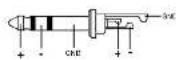
B TS JACK
DFX SEND - Master section
STEREO RETURN - Master section
CONTROL ROOM - Master section
DFX MUTE - Master section
MAIN MIX OUT
GR1, GR2, GR3 and GR4 OUT
AUX1, AUX2, AUX3 and DFX SEND
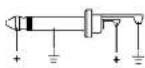
C TRS JACK Line input - all channels
D BALANCED XLR-F MAIN MIX OUT
1 ground
2 positive (or hot)
3 - negative (or cold)
E TRS JACK
Insert - mono channels
F RCA PLUG
2 TRACK IN - Master section
2 TRACK OUT - Master section

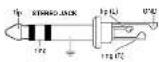
G STEREO JACK
Phones - Master section
15 User manual | ANTMIX Series
7 | SYSTEM CONNECTIONS
Check the correct functioning of the cables and always connect the cables properly according to the type of device and the mixer input/output.
Always use good quality cables.
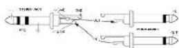
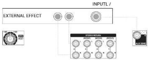
FIG. A | AUX / DFX POST
• AUX sends - 1, 2 and 3
Connect this output to one or more - daisy-chained - monitors
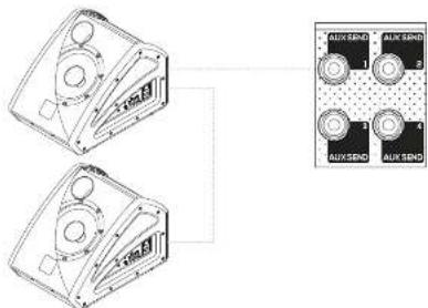
- DFX POST SEND
Connect to this output to an external effects unit.
Connect external effects unit outputs to STEREC RETURN inputs
ANTMIX Series | User manual

ANTMIX SERIES
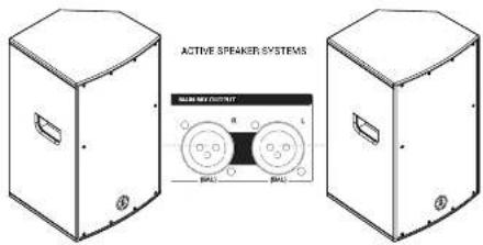
FIG. B | MAIN MIX OUT
Connect MAIN MIX outputs to powered speakers or amplifiers
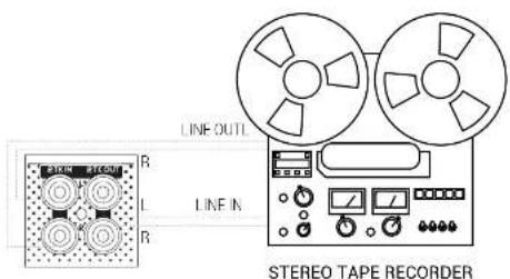
• 2TK IN / 2TK OUT
Connect your recorder to 2TK IN (from recorder outputs) and to 2TK OU (to recorder inputs) connectors.
8 | NOTES

INDICE
3 | DESCRIZIONE
3.1 INGRESSI & CONTROLLI DEI MIXER
3.1.1 INGRESSI MONO/STEREO

11 DISPLAY - DIGITAL PRESETS
MODULO BLUETOOTH - BTX 1624
• MANDATA DFX POST
natural_image
Technical line drawing of a device front panel with control knobs and buttons (no text or symbols visible)3 | DESCRIPTION
3.1 | ENTRÉES & CONTRÔLES DES TABLES DE MIXAGE
3.1.1 | ENTRÉES MONO/STÉRÉO

1 MIC INPUT
11 DISPLAY - DIGITAL PRESETS
3.1.4 | INTERFACE USB & APPLICATIONS
1 RECORD
MODULE BLUETOOTH: - BTX 1624
• DÉPART DFX POST
• 2TK IN / 2TK OUT
11 DISPLAY - DIGITAL PRESETS
MODUL BLUETOOTH ^1 - BTX 1624
3 Signal - (oper kalt)
E KLINKENSSTECKER SYMMETRISCH
Insert - Monokanale
F CINCH-STECKER
2 TRACK IN Master Section
- DFX POST SEND
11 DISPLAY - DIGITAL PRESETS
MÓDULO BLUETOOTH - BTX 1624
• ENVÍO DFX POST
ENG The information contained in this manual have been carefully drawn up and checked. However no responsibility will be assumed for any incorrectness. This manual cannot cover all the positive contingencies which may arise during the product installation and use. Should further information be desired, please contact us or our local distributor. A.E.B. Industrials Srl can not be considered responsible for damages which may be caused to people and things when using the product. Specifications and features are subject to change without prior notice.
The Bluetooth® word mark and logos are registered trademarks owned by the Bluetooth® SIG, Inc. and any use of such marks by AFB Industrials S.R.L. is under license. Other trademarks and trade names are those of their respective owners.
ENG - Download this manual in other languages on www.ant-intomusic.com