PRCDS - Circuit breakers Kopp - Free user manual and instructions
Find the device manual for free PRCDS Kopp in PDF.
| Product type | Mobile residual current device (PRCD-S) |
| Brand | Kopp |
| Model | PRCDS |
| Rated voltage | 230 V~ |
| Rated frequency | 50 Hz |
| Rated current | 16 A |
| Rated power | 3.6 kW |
| Rated fault current (IΔn) | 10 mA or 30 mA depending on version |
| Degree of protection (depending on version) | IP44, IP55 or IP66/68 |
| Ambient temperature | -25 °C to +45 °C (daily average ≤ +35 °C) |
| Conductor cross-section | 1 mm² to 2.5 mm² |
| Standards | DIN VDE 0661, EN 60721, DGUV information 203-006 (BGI 608) |
| Main functions | Residual current circuit breaker, detection and monitoring of protective conductor, voltage fault tripping |
| Spare parts | 2 housing screws, 2 anti-pinch devices, 2 strain relief devices, 4 strain relief screws |
| Application area | Small construction sites, mobile electrical appliances, use with extension cables or cable reels |
| Start-up process | Plug in the plug, press I-ON with bare hand (check of protective conductor) |
| Verification check | Regular test with the O-Test button; periodic inspection according to www.kopp.eu |
Frequently Asked Questions - PRCDS Kopp
User questions about PRCDS Kopp
0 question about this device. Answer the ones you know or ask your own.
Ask a new question about this device
Download the instructions for your Circuit breakers in PDF format for free! Find your manual PRCDS - Kopp and take your electronic device back in hand. On this page are published all the documents necessary for the use of your device. PRCDS by Kopp.
USER MANUAL PRCDS Kopp
natural_image
Black-and-white photo of a man in workwear working on a metal panel or fixture in an indoor space (no visible text or symbols)
natural_image
Person in plaid shirt crouching on wooden deck using power tools, with equipment and trees in background (no visible text or symbols)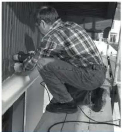
natural_image
Man in plaid shirt using power tool on a wall, no visible text or symbolsKopp GERMANY
PRCD-S
natural_image
Close-up of a black industrial pipe fitting with two control buttons (no visible text or symbols)

Operating instructions 32-41
Einleitung
$$ S = \text { Saftey } $$
text_image
Technical diagram of a mechanical assembly with numbered components and internal cross-sections
Beispiel:
text_image
Technical diagram of a mechanical device with labeled components and numbered parts, including sections A, B, C, and numbered annotations 4, 5, 6, 7, 8, 9.Operating instructions 32-41
Inleiding
text_image
Technical diagram of a mechanical assembly with numbered components and cross-sectional views
Voorbeeld:
text_image
Technical diagram of a mechanical device with labeled components and numbered parts, including sections A, B, C, and numbered annotations 4, 5, 6, 7, 8, 9.④2 Knikbeschermbuisjes
⑤2 Trekontlastingsklemmen
⑥4 Trekontlastingsschroeven
⑦ I-ON Knop
⑧Glimlamp (rood)
⑨ O-Test-Knop
Ⓐ Veiligheidsaarddraad (PE)
B Neutrale geleider (N)
© Buitenste geleider(Phase L)

Operating instructions
32-41
Introduction
text_image
Technical diagram of a mechanical assembly with numbered components and cross-sectional views
Exemple :
Operating instructions 32-41
Initiation
You've chosen a high quality product, prepared with the utmost care.
Only a proper installation and start-up ensures reliable and trouble-free operation.
- Please familiarize yourself with the user manual before installing.
- Retain instruction for future reference.
Safety notes
Installation only by persons with pertinent electrical knowledge and experience.
Improper installation risks:
- Your own life.
- The life of the users of the electrical system.
With improper installation, you risk serious property damage, such as due to fire.
You risk personal liability in case of personal or property damage.
Contact an electrician!
The following specialized knowledge is especially necessary for installation:
- the 5 „safety rules“ to be applied: disconnect; against being switched on again; ensure that no voltage is present; ground and short-circuit; cover or fence off neighboring live parts.
- selection of the suitable tools, measuring equipment and personal protective equipment, if necessary.
• evaluation of the measurement results. - selection of the electrical installation material to ensure the switch-off conditions.
• IP-degrees of protection.


General notes
• installation of the electrical installation material.
- type of supply network (TNSystem, IT-system, TT-system) device with electronic residual current evaluation that and the resulting connection conditions (ground switches on all poles and was designed for connection without a special grounding conductor, protective within a cable. grounding, necessary additional measures, etc...).
Follow the connection diagrams that are included for connection.
Damaged or partially damaged devices may not be nected or used.
Before installation, ensure that the wires to be connected to the device are not live.
Observe the rules of electrical engineering and 0100
PRCD-S stands for: Portable Residual Current Device, S = Safety
con-
The portable safety switch PRCD-S was developed based on the recommendation of the BG for connection to unknown outlets and makes safe current consumption from these supply points possible.
DINeVERED-S inspect the socket if the phase L, the neutral conductor N and the protective conductor PE is
- present,
• properly connected, - are not inverted
And switch on only on a safe socket outlet
The ground wire is checked when switched on and monitored during operation.
The PRCD-S recognizes system errors in the fixed install-

ation and cannot be switched on if a fault is recognized. As soon as a fault occurs (e.g. ground wire breakage), the PRCD-S switches off automatically.
This increases the level of protection against dangerous shock currents.
The PRCD-S will not switch off if external voltage is applied to the ground wire, e.g. due to drilling into wire.
Due to the fact that the PRCD-S does not switch off, the upstream protective device can activate and interrupt the circuit.
The device is designed to recognize
• alternate fault currents
• pulsating direct fault currents
• phase-controlled fault currents
The PRCD-S has the following functions
• residual current device (DI)
• ground wire identification (testing before operation)
• ground wire monitoring (testing during operation)
- undervoltage release
• detection of mains voltage on the ground
switching on*
- maintaining the ground wire function in case of external voltage on the ground wire during operation
Fault detection – the PRCD-S detects and protects in case of the following system errors
• N-wire interrupted
- detection of mains voltage on the ground wire switchgeonal
- missing PE-wire
- maintaining the ground wire function in case of external voltage on the ground wire during operation
• Phase L and PE-wire reversed
• Phase L and PEN-wire reversed
- PE-wire live
- PEN-wire live
- rated residual currents 10 mA or 30 mA (depending upon design)
• power outage / power interruption
* Follow the instructions under Switching ON procedure.
wire while


Components
①lid
② Housing
③2 Housing screws
④2 Protection rubber sleeves
⑤2 Strain relief clamps
⑥4 Strain relief screws
Area of application
The PRCD-S is especially suitable for small construct site as well as for all mobile electric devices.
In order to be able to monitor terminal devices and feed wires, we recommend connecting the PRCD-S as close to the intended power supply outlet as possible.
text_image
Technical diagram of a mechanical assembly with numbered components and internal cross-sections
Example:
When using an extension cord or a cable drum, the PRCD-S must be plugged in between the outlet intended for power supply (fixed installation) and the extension cable/c drum.
Do not use the PRCD-S
• for operating freezers and refrigerators.
- the PRCD-S switches the off in case of power outage and prevents automatic restart when power is restored.
- as an ON and OFF switch for switching machines with high starting currents.
PRCD-S cannot be used
The PRCD-S requires the presence of a ground wire. If a ground wire interruption occurs during operation, the PRCD-S switches off on all poles.
Therefore, the operation of a 2-pole voltage isolating transformer, power generator, etc.) is sible.
Switching ON procedure
• Plug the PRCD-S mains plug into the existing outlet
- As soon as the PRCD-S mains plug is plugged in and the lePRCD-S is supplied with power, the wiring of the outlet is automatically checked by the PRCD-S for faults and the existence of the ground wire.
- Activate the I-ON button with your bare hand (switch ON PRCD-S manually)
Do NOT switch on with gloves!
- While the I-ON button is being switched on with your bare hand, the PRCD-S checks whether the ground wire is free of mains voltage.
The PRCD-S can only be switched on in this case.
Important note – follow at all times:
- So that the PRCD-S can properly check for “voltage on the ground wire” during the switch-on pro-
source ce(s), the PRCD-S may not be switched on with gloves or not other insulating objects. - The switch-on process must be performed prop meaning with bare hands!


Important note for operation with gloves.
The PRCD-S recognizes through the I-ON-button ⑦ whether the ground wire is conducting mains voltage and thus prevents switching on.
text_image
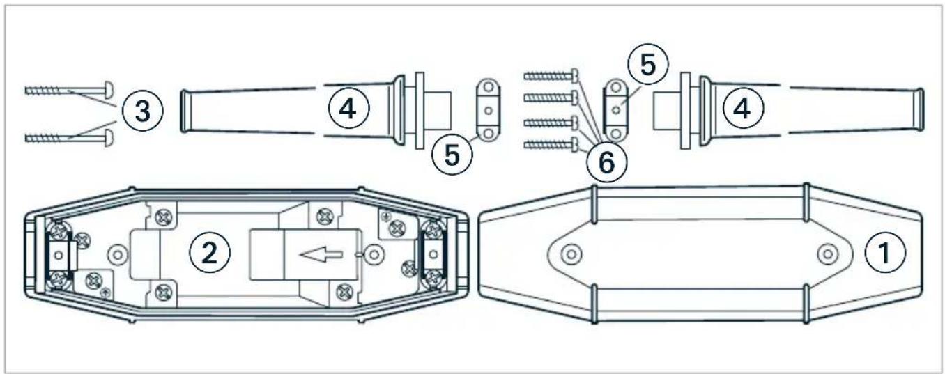
Technical diagram of a mechanical device with labeled components and numbered parts, including sections A, B, C, and numbered annotations 4, 5, 6, 7, 8, 9.④2 Protection rubber sleeves
⑤ 2 Strain relief clamps
⑥4 Strain relief screws
⑦ I-ON button
⑧ Glow lamp red
⑨ O-Test-button
Ⓐ Ground wire (PE)
B Neutral wire (N)
© Outer wire (Phase L)

Commissioning - test sequence
The PRCD-S must fundamentally be checked as follows before every use:
• Plug the mains plug into existing outlet
- Activate the "I-ON" button with bare hands
- Red glow lamp illuminates - PRCD-S is switched on and ready for use.
- Activate "O-Test" button residual current device is created.
• PRCD-S switches off.
• Red glow lamp switches off.
If the PRCD-S does not activate by means of the O-Test button, the device must immediately be disconnected the mains and checked.
After the PRCD-S is switched on again, the device must be able to be operated.
Otherwise, Table 1 aids in troubleshooting.
Regulations and rules
The PRCD-S was developed based on DIN VDE 0661 Portable protective devices intended for an increase in the protection level for a rated voltage U_n = 230 V , rated current I_ N ≤ 16 A , rated residual current I_ N ≤ 30 mA .
The employer's liability insurance associations (BG ETEM (Energie Textil Elektro) among others) recommend the PRCD-S as an effective protective measure for connecting portable consumers to outlets of unknown protection (unknown protective device) in their guidelines (BGI 608 / DGUV information 203-006). from
connected
Caution
The PRCD-S or the entire connection set, respectively, must be subjected to a regular repeat test.
Before opening the PRCD-S, the mains plug must always be unplugged!


In-house manufacturing
Depending upon the existing plug system, the connection wires can be manufactured by an electrician himself.
a. Loosen the two screw the housing and lift off lid ①.
b. Open the strain relief clamp ^5 and remove completely.
c. Cut the device supply wire at the desired the device plug and strip the two ends of the wire.
- The length of the wire before the PRCD-S must be a minimum of 1.5 m + 10 %.
- The length of the wire after the PRCD-S minimum of 1.5 m.
d. Strip single cores and install wire-end sleeves (max. diameter 2.5 mm ^4 ).
e. Push the protective rubber sleeves ^4 over the ends of the wires.
f. Connect the connection cable to the terminal clamps Ⓐ, beginning with the ground wire.
g. Observe: input side
(arrow direction = direction of current flow)
h. Input side: connect Phase L to terminal ^© , neutral wire N to terminal ^®
i. Output side: connect neutral wire N to ^® , terminal Phase L to terminal Ⓐ , ground wire PE to terminal Ⓐ
j. Attach the connecting wires and protective rubber sleeves ④ with the strain relief clamps.
Check protective rubber sleeves and strain relief clamps for proper fit.
k. plane the air ① on the housing ② and tighten the screws ③ with a torque of 1 Nm.
The wire lengths of the PRCD-S made by the manufacturer can be elevated from the dimensions listed above.
Repeat test
The PRCD-S must be checked regularly.
Instructions for this can be found at www.kopp.eu.

| Connection situation | PRCD-S reaction Possibilities / causes / faults Solution | ||
| PRCD-S connected to common outlet | PRCD-S cannot be switched on | Outlet without power supply | Check power supply |
| Outlet probably not fault-free | Have outlet checked by an electrician | ||
| Plug PRCD-S into another outlet to test it | |||
| PRCD-S - cable set defective Check/replace cable set | |||
| No ground wire exists | Have outlet checked by an electrician | ||
| Plug PRCD-S into another outlet to test it | |||
| L/N/PE reversed | Have outlet checked by an electrician | ||
| Plug PRCD-S into another outlet to test it | |||
| Voltage on ground wire | Plug PRCD-S into another outlet | ||
| Have outlet checked by an electrician | |||
| PRCD-S can only be switched on with gloves | Voltage on ground wire | Correct faulty ground wire connection | |
| Operation on power generator | PRCD-S cannot be switched on | No ground wire exists | Operation on power generators is not possible |
| Operation on isolating transformer | PRCD-S cannot be switched on | No ground wire exists | Operation on isolating transformers is not possible |


Table 1 – Technical data
| Rated voltage 230 V~ | |
| Rated frequency 50 Hz | |
| Rated currency 16 A | |
| Rated output 3.6 kW | |
| Rated residual current I_ n (depending upon design) | 30 mA10 mA |
| Degree of protection (depending upon design) | IP 44IP 55 |
| Design (encapsulated) | IP 66/68 |
| Ambient temperature -25 °C to +45 °C (with a daily average value that does not exceed +35 °C) | |
Wire cross-section 1 mm² to 2.5 mm²
Switching position indicator ON: glow lamp (red) illuminates
operation ON I-ON
Off/Test O-Test
Certification mark


Standards DIN VDE 0661, EN 60 721
Guidelines DGUV Information 203-006 (formerly BGI 608)
KOPP GERMANY
Heinrich Kopp GmbH
Alzenauer Str. 68
63796 Kahl a. Main
DEUTSCHLAND
www.kopp.eu