LSDG389VS - Tumble drier LG - Free user manual and instructions
Find the device manual for free LSDG389VS LG in PDF.

User questions about LSDG389VS LG
0 question about this device. Answer the ones you know or ask your own.
Ask a new question about this device
Download the instructions for your Tumble drier in PDF format for free! Find your manual LSDG389VS - LG and take your electronic device back in hand. On this page are published all the documents necessary for the use of your device. LSDG389VS by LG.
USER MANUAL LSDG389VS LG
Please read this manual carefully before operating your dryer and retain it for future reference.
LSDE388VS LSDG389VS
IMPORTANT SAFETY INSTRUCTIONS
What to Do if You Smell Gas 3
Basic Safety Precautions 4
California Safe Drinking Water and Toxic
Enforcement Act 4
Grounding Instructions ....5
Safety Instructions for Installation ....5
Safety Instructions for Steam Functions ....6
Safety Instructions for Connecting Electricity .....7
PARTS AND FEATURES
Special Features 8
Key Parts and Components 9
INSTALLATION INSTRUCTIONS
IMPORTANT: Read all installation instructions completely before installing and operating your dryer! 10
Installation Location Requirements 10
Clearances 10
Installation With Optional
Pedestal Base or Stacking Kit 11
Optional Accessories 11
Leveling the Dryer 12
To Remove Door 13
To Install Door 14
Changing the Dryer Vent Location 15
Venting the Dryer 16
Connecting Gas Dryers 18
Connecting Electric Dryers 20
Special Requirements for Manufactured
or Mobile Homes 25
Final Installation Check 25
Duct Condition Test 26
HOW TO USE
Control Panel Features 27
Operating the Dryer 28
Cycle Guide 29
Sorting Loads 30
Loading the Dryer 30
Check the Lint Filter Before Every Load 30
The LCD Display 31
Cycle Setting Buttons 33
Special Functions 34
Custom Program 35
Steam Functions 35
Steam Cycle Guide 37
TROUBLESHOOTING
Regular Cleaning 38
Before Calling for Service 39
Using SmartDiagnosis ^TM 42
THANK YOU!
Congratulations on your purchase and welcome to the LG family. Your new LG Dryer combines the most advanced drying sensor technology with simple operation and high
Follow the operating and care in- structions in this manual and your washer will provide many years of reliable service
OPTIONAL ACCESSORIES/ SPECIFICATIONS
Optional Accessories 43
Pedestal Installation 44
Stacking Kit Installation 46
Key Dimensions and Specifications 47
WARRANTY 48
natural_image
Silhouette of a clothes rack with a cloth and a spray bottle, no text or symbols present©
READ ALL INSTRUCTIONS BEFORE USE
WARNING
For your safety, the information in this manual must be followed to minimize the risk of fire or explosion, electric shock, or to prevent property damage, personal injury, or loss of life.
BASIC SAFETY PRECAUTIONS
WARNING:
To reduce the risk of fire, electric shock, or personal injury when using this appliance, follow basic precautions, including the following:
- Read all instructions before using the dryer.
- Before use, the dryer must be properly installed as described in this manual.
- Do not place items exposed to cooking oils in your dryer. Items contaminated with cooking oils may contribute to a chemical reaction that could cause a load to catch fire.
- Do not dry articles that have been previously cleaned in, washed in, soaked in, or spotted with gasoline, dry-cleaning solvents, or other flammable or explosive substances as they give off vapors that could ignite or explode.
- Do not reach into the dryer if the drum or any other part is moving.
- Do not repair or replace any part of the dryer or attempt any servicing unless specifically recommended in this Use and Care Guide or in published user-repair instructions that you understand and have the skills to carry out.
- Do not tamper with controls.
-
Before the dryer is removed from service or discarded, remove the door to the drying compartment.
-
Do not allow children to play on or in the dryer. Close supervision of children is necessary when the dryer is used near children.
- Do not use fabric softeners or products to eliminate static unless recommended by the manufacturer of the fabric softener or product.
- Do not use heat to dry articles containing foam rubber or similarly textured rubber-like materials.
- Keep area around the exhaust opening and adjacent surrounding areas free from the accumulation of lint, dust, and dirt.
- The interior of the dryer and exhaust vent should be cleaned periodically by qualified service personnel.
- Do not install or store the dryer where it will be exposed to the weather.
- Always check the inside of the dryer for foreign objects.
- Clean lint screen before or after each load.
CALIFORNIA SAFE DRINKING WATER AND TOXIC ENFORCEMENT ACT
This act requires the governor of California to publish a list of substances known to the state to cause cancer, birth defects, or other reproductive harm and requires businesses to warn customers of potential exposure to such substances.
Gas appliances can cause minor exposure to four of these substances, namely benzene, carbon monoxide, formaldehyde, and soot, caused primarily by the incomplete combustion of natural gas or LP fuels.
Properly adjusted dryers will minimize incomplete combustion. Exposure to these substances can be minimized further by properly venting the dryer to the outdoors.
READ ALL INSTRUCTIONS BEFORE USE
⚠ WARNING For your safety, the information in this manual must be followed to minimize the risk of fire or explosion, electric shock, or to prevent property damage, personal injury, or loss of life.
GROUNDING INSTRUCTIONS
This appliance must be grounded. In the event of malfunction or breakdown, grounding will reduce the risk of electric shock by providing a path of least resistance for electric current. This appliance must be equipped with a cord having an equipment-grounding conductor and a grounding plug. The plug must be plugged into an appropriate outlet that is properly installed and grounded in accordance with all local codes and ordinances.
WARNING — Improper
connection of the equipment-grounding conductor can result in a risk of electric shock.
Check with a qualified electrician or service person if you are in doubt as to whether the appliance is properly grounded.
Do not modify the plug provided with the appliance. If it will not fit the outlet, have a proper outlet installed by a qualified electrician.
This appliance must be connected to a grounded metal, permanent wiring system or an equipment-grounding conductor must be run with the circuit conductors and connected to the equipment-grounding terminal or lead on the appliance.
Electrical shock can result if the dryer is not properly grounded.
SAFETY INSTRUCTIONS FOR INSTALLATION
⚠ WARNING: To reduce the risk of fire, electric shock, or personal injury when using this appliance, follow basic precautions, including the following:
- Properly ground dryer to conform with all governing codes and ordinances. Follow details in the installation instructions. Electrical shock can result if the dryer is not properly grounded.
- Before use, the dryer must be properly installed as described in this manual. Electrical shock can result if the dryer is not properly grounded.
• Install and store the dryer where it will not be exposed to temperatures below freezing or exposed to the weather. - All repairs and servicing must be performed by an authorized servicer unless specifically recommended in this Owner's Guide. Use only authorized factory parts. Failure to follow this warning can cause serious injury, fire, electrical shock, or death.
-
To reduce the risk of electric shock, do not install the dryer in humid spaces. Failure to follow this warning can cause serious injury, fire, electrical shock, or death.
-
Connect to a properly rated, protected, and sized power circuit to avoid electrical overload. Improper power circuit can melt, creating electrical shock and/or fire hazard.
- Remove all packing items and dispose of all shipping materials properly. Failure to do so can result in death, explosion, fire, or burns.
- Place dryer at least 18 inches above the floor for a garage installation. Failure to do so can result in death, explosion, fire, or burns.
- Keep all packaging from children. Packaging material can be dangerous for children. There is a risk of suffocation.
- Do not install nearby heat item. Such as stove, cooking oven. Failure to do so can cause deform, smoke and fire.
- Do not place candle and cigarettes on top of the product. Failure to do so can cause deform, smoke and fire.
- Remove all protective vinyl film from the product. Failure to do so can cause deform, smoke and fire.
READ ALL INSTRUCTIONS BEFORE USE
⚠ WARNING For your safety, the information in this manual must be followed to minimize the risk of fire or explosion, electric shock, or to prevent property damage, personal injury, or loss of life.
SAFETY INSTRUCTIONS FOR INSTALLATION
⚠ WARNING: To reduce the risk of personal injury, adhere to all industry recommended safety procedures including the use of long sleeved gloves and safety glasses. Failure to follow all of the safety warnings in this manual could result in property damage, personal injury or death.
Exhaust/Ducting:
- Gas dryers MUST be exhausted to the outside. Failure to follow these instructions can result in fire or death.
- The dryer exhaust system must be exhausted to the outside of the dwelling. If the dryer is not exhausted outdoors, some fine lint and large amounts of moisture will be expelled into the laundry area. An accumulation of lint in any area of the home can create a health and fire hazard.
- Use only rigid metal or flexible metal 4-inch diameter ductwork inside the dryer cabinet or for exhausting to the outside. Use of plastic or other combustible ductwork can cause a fire. Punctured ductwork can cause a fire if it collapses or becomes otherwise restricted in use or during installation.
-
Ductwork is not provided with the dryer, and you should obtain the necessary ductwork locally. The end cap should have hinged dampers to prevent backdraft when the dryer is not in use. Failure to follow these instructions can result in fire or death.
-
The exhaust duct must be 4 inches (10.2 cm) in diameter with no obstructions. The exhaust duct should be kept as short as possible. Make sure to clean any old ducts before installing your new dryer. Failure to follow these instructions can result in fire or death.
- Rigid or semi-rigid metal ducting is recommended for use between the dryer and the wall. In special installations when it is impossible to make a connection with the above recommendations, a UL-listed flexible metal transition duct may be used between the dryer and wall connection only. The use of this ducting will affect drying time. Failure to follow these instructions can result in fire or death.
- DO NOT use sheet metal screws or other fasteners which extend into the duct that could catch lint and reduce the efficiency of the exhaust system. Secure all joints with duct tape. For complete details, follow the Installation Instructions. Failure to follow these instructions can result in fire or death.
SAFETY INSTRUCTIONS FOR STEAM FUNCTIONS
⚠ WARNING: To reduce the risk of fire, electric shock, or personal injury when using this appliance, follow basic precautions, including the following:
- Do not open the dryer door during steam cycles. Failure to follow these instructions can result in a burn hazard.
-
Do not dry articles that have been previously cleaned in, washed in, soaked in, or spotted with gasoline, dry-cleaning solvents, or other flammable or explosive substances as they give off vapors that could ignite or explode. Failure to follow these instructions can result in fire or death.
-
Do not fill the steam feeder with gasoline, dry-cleaning solvents, or other flammable or explosive substances. Failure to follow these instructions can result in fire or death.
- Do not touch the steam nozzle in the drum during or after the steam cycle. Failure to follow these instructions can result in a burn hazard.
- Do not fill the steam feeder with hot water (over 86 °F/30 °C). Failure to follow these instructions can result in a burn hazard.
READ ALL INSTRUCTIONS BEFORE USE
⚠ WARNING For your safety, the information in this manual must be followed to minimize the risk of fire or explosion, electric shock, or to prevent property damage, personal injury, or loss of life.
SAFETY INSTRUCTIONS FOR CONNECTING ELECTRICITY
⚠ WARNING: To reduce the risk of fire, electric shock, or personal injury when using this appliance, follow basic precautions, including the following:
- Do not, under any circumstances, cut or remove the ground prong from the power cord. To prevent personal injury or damage to the dryer, the electrical power cord must be plugged into a properly grounded outlet.
- For personal safety, this dryer must be properly grounded. Failure to do so can result in electrical shock or injury.
- Refer to the installation instructions in this manual for specific electrical requirements for your model. Failure to follow these instructions can create an electrical shock hazard and/or a fire hazard.
- This dryer must be plugged into a properly grounded outlet. Electrical shock can result if the dryer is not properly grounded. Have the wall outlet and circuit checked by a qualified electrician to make sure the outlet is properly grounded. Failure to follow these instructions can create an electrical shock hazard and/or a fire hazard.
-
The dryer should always be plugged into its own individual electrical outlet which has a voltage rating that matches the rating plate. This provides the best performance and also prevents overloading house wiring circuits which could cause a fire hazard from overheated wires.
-
Never unplug your dryer by pulling on the power cord. Always grip plug firmly and pull straight out from the outlet. The power cord can be damaged, resulting in a risk of fire and electrical shock.
- Repair or replace immediately all power cords that have become frayed or otherwise damaged. Do not use a cord that shows cracks or abrasion damage along its length or at either end. The power cord can melt, creating electrical shock and/or fire hazard.
- When installing or moving the dryer, be careful not to pinch, crush, or damage the power cord. This will prevent injury and prevent damage to the dryer from fire and electrical shock.
SAVE THESE INSTRUCTIONS
SPECIAL FEATURES
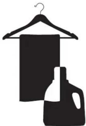
A EASY-TO-USE CONTROL PANEL
Rotate the Cycle Selector Knob to select the desired dry cycle. Add cycle options or adjust settings with the touch of a button.
B EASY-ACCESS REVERSIBLE DOOR
Wide-opening door provides easy access for loading and unloading. Door swing can be reversed to adjust for installation location.
C ULTRA-CAPACITY STAINLESS STEEL DRUM WITH DRUM LIGHT
The ultra-large stainless steel drum offers superior durability. The drum is equipped with a yellow light that illuminates when the dryer door is open and turns off when the door is closed.
D STEAM FUNCTIONS
LG's steam technology allows you to inject fabrics with a swirling jet of hot steam to refresh clothes, reduce static, and make ironing easier. Simply select the STEAMFRESH™ cycle, or you can add a Steam option to selected cycles.
E LCD DISPLAY SCREEN
The easy-to-read LCD screen shows cycle options and information and provides status messages during operation.
F FLOW SENSE™ DUCT BLOCKAGE SENSING SYSTEM INDICATOR
The FLOW SENSE™ duct blockage sensing system detects and alerts you to blockages in the ductwork that reduce exhaust flow from the dryer. Clean exhaust systems increase efficiency and reduce drying times.
G DUAL SENSOR+
Enhanced dual sensor possible to sense wetness level of clothes more accurately.
Regardless of load size, it can be save a energy and earn more uniformity dryness performance.
text_image
Diagram of a washing machine with labeled parts including door, fan, and control panelH SMARTDIAGNOSISTM
Should you experience any technical difficulty with your dryer, it has the capability of transmitting data by phone to the Customer Information Center. The call center agent records the data transmitted from your machine and uses it to analyze the issue, providing a fast and effective diagnosis (refer to page 42).


Protocol P154 Sanitization Performance of Residential Clothes dryer
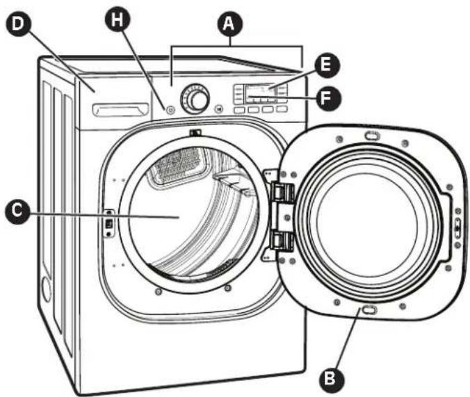
KEY PARTS AND COMPONENTS
In addition to the special features and components outlined in the Special Features section, there are several other important components that are referenced in this manual.
A FRONT-MOUNT LINT FILTER
Front-mount lint filter allows for easy access and cleaning after every load.
B LEVELING FEET
Four leveling feet (two in the front, and two in the back) adjust to improve dryer stability on uneven floors.
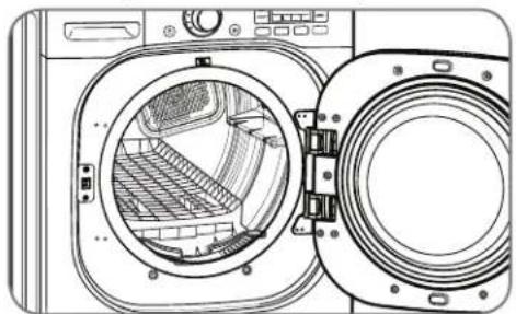
© DRYING RACK
Use the drying rack with the RACK DRY cycle to safely dry such items as sweaters, delicates and gym shoes without tumbling or overheating.
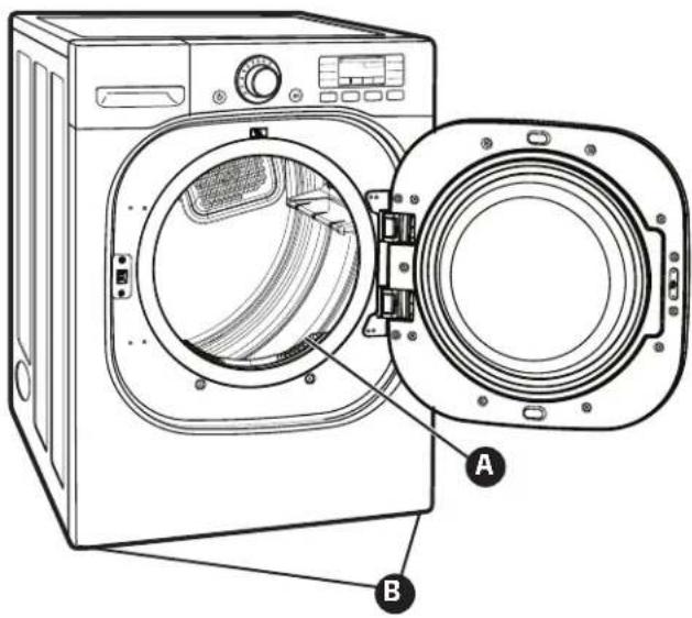
text_image
Diagram of a front-loading washing machine with labeled parts A and B, showing internal components and door opening.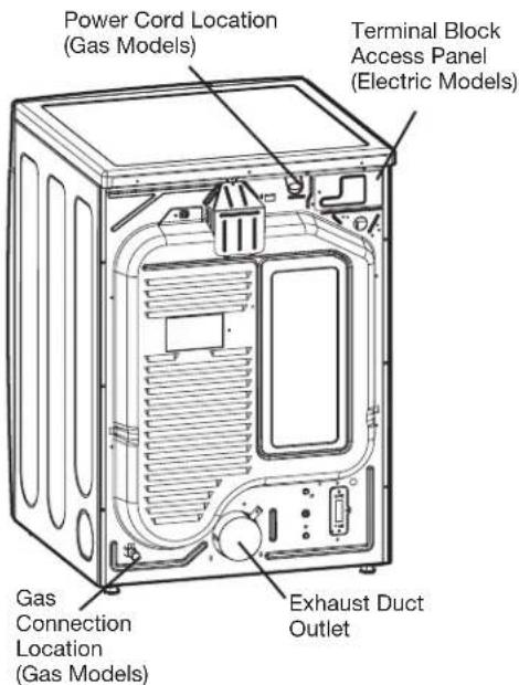
text_image
Power Cord Location (Gas Models) Terminal Block Access Panel (Electric Models) Gas Connection Location (Gas Models) Exhaust Duct OutletRear of Dryer
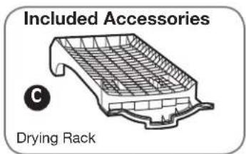
text_image
Included Accessories C Drying RackIMPORTANT: Read all installation instructions completely before installing and operating your dryer!
It is important that you review this entire manual before installing and using your dryer. Detailed instructions concerning electrical connections, gas connections, and exhaust requirements are provided on the following pages.
INSTALLATION LOCATION REQUIREMENTS
■ A location that allows for proper exhaust installation. A gas dryer must be exhausted to the outdoors. See Venting Requirements.
■ A grounded electrical outlet located within 2 ft. (61 cm) of either side of the dryer. See Electrical Requirements.
A sturdy floor to support the total dryer weight of 200 lbs (90.7 kg). The combined weight of a companion appliance should also be considered.
A level floor with a maximum slope of 1 inch (2.5 cm) under entire dryer. If slope is greater than 1 inch (2.5 cm), install Extended Dryer Feet Kit. Clothes may not tumble properly, and automatic sensor cycles may not operate correctly if dryer is not level.
For a garage installation, you will need to place the dryer at least 18 inches (46 cm) above the floor. If using a pedestal, you will need 18 inches (46 cm) to the bottom of the dryer.
Do not operate your dryer at temperatures below 45 °F ( 7 °C ). At lower temperatures, the dryer might not shut off at the end of an automatic cycle. This can result in longer drying times.
The dryer must not be installed or stored in an area where it will be exposed to water and/or weather.
Check code requirements. Some codes limit, or do not permit, installation of the dryer in garages, closets, mobile homes or sleeping quarters. Contact your local building inspector.
NOTE: No other fuel-burning appliance can be installed in the same closet as a dryer.
CLEARANCES
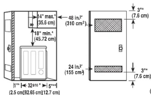
text_image
14" max." (35.6 cm) 18" min." (45.72 cm) 48 in.2" (310 cm²) 24 in.2" (155 cm²) 3"" (7.6 cm) 3"" (7.6 cm) 1"" 32 9/16 " 5"*" (2.5 cm)82.65 cm)(12.7 cm)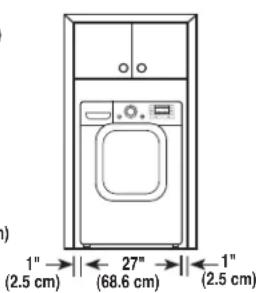
text_image
(a) 1" (2.5 cm) 27" (68.6 cm) 1" (2.5 cm)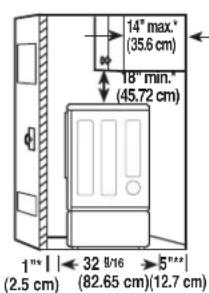
text_image
14" max." (35.6 cm) 18" min." (45.72 cm) 1" (2.5 cm) 32 8/16 (82.65 cm) 5" (12.7 cm)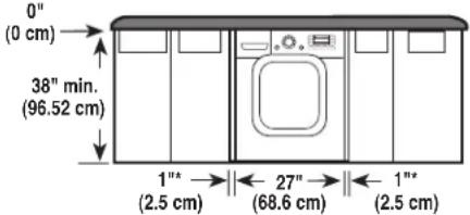
text_image
0" (0 cm) 38" min. (96.52 cm) 1"* (2.5 cm) 27" (68.6 cm) 1"* (2.5 cm)Installation spacing for recessed area or closet installation
The following spacing dimensions are recommended for this dryer. This dryer has been tested for spacing of 0 inches (0 cm) clearance on the sides and rear. Recommended spacing should be considered for the following reasons:
■Additional spacing should be considered for ease of installation and servicing.
■Additional clearances might be required for wall, door and floor moldings.
■ Additional spacing should be considered on all sides of the dryer to reduce noise transfer.
For closet installation, with a door, minimum ventilation openings in the top and bottom of the door are required. Louvered doors with equivalent ventilation openings are acceptable.
■ Companion appliance spacing should also be considered.
Suggestion: There should be at least a little space around the dryer (or any other appliance) to eliminate the transfer of vibration from one to the other. Too much vibration, it could cause them to make noise or touch each other causing paint damage and making even more noise.
INSTALLATION WITH OPTIONAL PEDESTAL BASE OR STACKING KIT
IMPORTANT: If you are installing your dryer using an optional pedestal base or stacking kit, please refer to Optional Accessories in this manual or to the instructions for your pedestal or stacking kit before proceeding with the installation.
Recommended installation spacing for cabinet installation
■ For cabinet installation, with a door, minimum ventilation openings in the top of the cabinet are required.
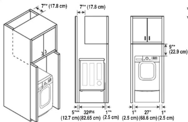
text_image
7" (17.8 cm) 7" (17.8 cm) 5" (12.7 cm) 32°/16 1" (2.5 cm) 9" (22.9 cm) (12.7 cm) (82.65 cm) (2.5 cm) (2.5 cm) (68.6 cm) (2.5 cm)*Required spacing
** For side or bottom venting, 2 inches (5.1 cm) spacing is allowed.
Recommended installation spacing for recessed or closet installation, with stacked washer and dryer
■ The dimensions shown are for the recommended spacing.
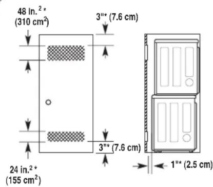
text_image
48 In.²* (310 cm²) 3"" (7.6 cm) 24 In.²* (155 cm²) 3"" (7.6 cm) 1"" (2.5 cm)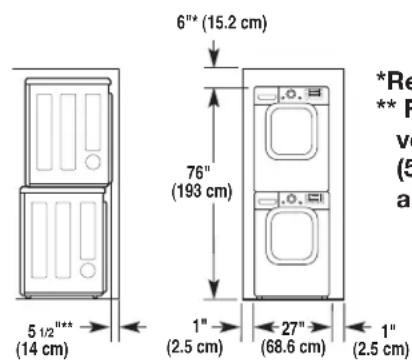
text_image
6"* (15.2 cm) 76" (193 cm) 1" (2.5 cm) 27" (68.6 cm) 1" (2.5 cm) 5 1/2"** (14 cm) *Re ** F ve (5 al*Required spacing ** For side or bottom venting, 2 inches (5.1 cm) spacing is allowed.
OPTIONAL ACCESSORIES
For these and other LG products, contact your local LG dealer, or visit our Web site at www.lg.com
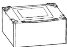
natural_image
Line drawing of a rectangular electronic component with mounting holes and a central square (no text or symbols)Pedestal (sold separately)
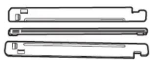
Stacking Kit (sold separately)
LEVELING THE DRYER
WARNING
- To reduce the risk of personal injury, adhere to all industry recommended safety procedures including the use of long sleeved gloves and safety glasses.
- Failure to follow all of the safety warnings in this manual could result in property damage, personal injury or death.
To ensure that the dryer provides optimal drying performance, it must be level. To minimize vibration, noise, and unwanted movement, the floor must be a perfectly level, solid surface.
NOTE: Adjust the leveling feet only as far as necessary to level the dryer. Extending the leveling feet more than necessary can cause the dryer to vibrate.
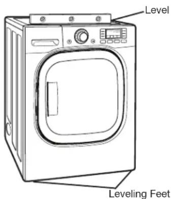
text_image
Level Leveling Feet1 Position the dryer in the final location. Place a level across the top of the dryer.
- All four leveling feet must rest solidly on the floor. Gently push on the top corners of the dryer to make sure that the dryer does not rock from corner to corner.
If you are installing the dryer on the optional pedestal, you must use the leveling feet on the pedestal to level the dryer. The dryer leveling feet should be fully retracted.
natural_image
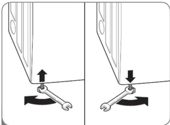
Diagram showing two mechanical components with wrenches and directional arrows indicating movement (no text or symbols)2 Use an adjustable wrench to turn the leveling feet. Turn clockwise to raise the dryer or counterclockwise to lower it. Raise or lower the leveling feet until dryer is level from side to side and front to back.
Make sure that all 4 leveling feet are in firm contact with the floor.
INSTALLATION INSTRUCTIONS
TO REMOVE DOOR
WARNING
THE DRYER DOOR IS VERY LARGE AND HEAVY. Failure to follow the instructions below can result in damage to the dryer, property damage or personal injury.
- To avoid damage to the dryer or the door, support the door with a stool or box that fits under the door, or have an assistant support the weight of the door.
• Always reverse the door BEFORE stacking the dryer on top of the washer. - Avoid dropping the door to avoid damage to the door or the floor.
text_image
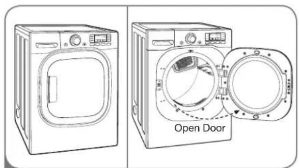
Open Door1 Open the door to reverse.
text_image
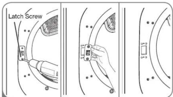
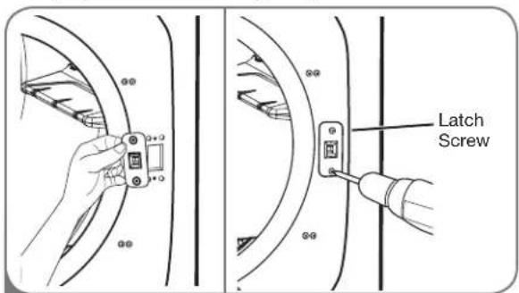
Latch Screw4 Remove two screws and disassembly Latch.
natural_image
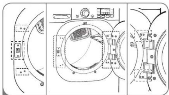
Technical line drawing of a washing machine interior with control panel and buttons (no text or symbols)2 Check screws to unravel (Left 6, Right 4).
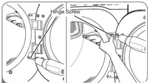
text_image
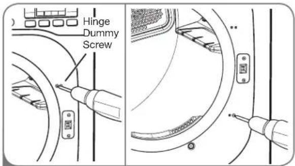
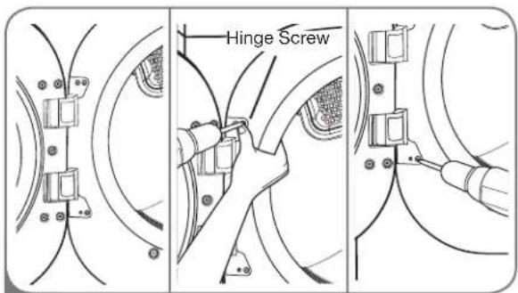
Hinge Screw5 Hold on the hinge while remove 4 screws of hinge (to prevent door dropping).
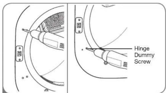
text_image
Hinge Dummy Screw3 Remove four dummy screws by driver.
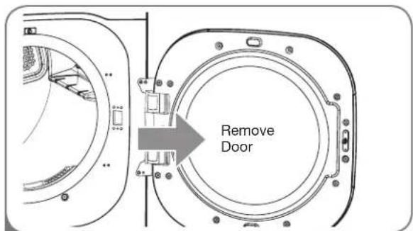
text_image
Remove Door6 Remove door from cabinet cover.
INSTALLATION INSTRUCTIONS
TO INSTALL DOOR
WARNING
THE DRYER DOOR IS VERY LARGE AND HEAVY. Failure to follow the instructions below can result in damage to the dryer, property damage or personal injury.
- To avoid damage to the dryer or the door, support the door with a stool or box that fits under the door, or have an assistant support the weight of the door.
• Always reverse the door BEFORE stacking the dryer on top of the washer. - Avoid dropping the door to avoid damage to the door or the floor.
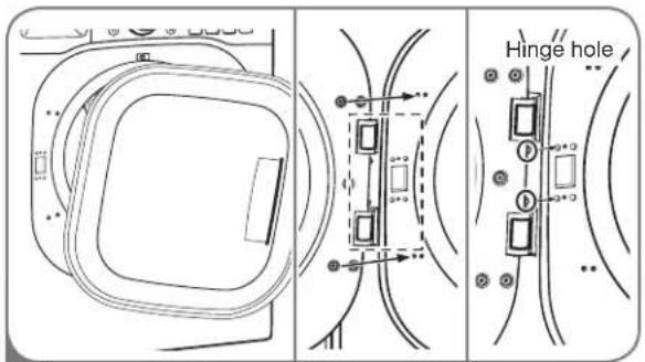
text_image
Hinge hole1 Move door to left side and insert a hinge to hinge hole.
text_image
Hinge Dummy Screw4 Screw down four dummy screws right side.
text_image
Hinge Screw2 Hold on hinge while screw down a hinge (to prevent door dropping).

text_image
Swing Door5 Check properly door installed by swing door.
text_image
Latch Screw3 Insert latch to right side and screw down latch.
CHANGING THE DRYER VENT LOCATION
WARNING
- Use a heavy metal vent.
- Do not use plastic or thin foil duct.
- Clean old ducts before installing this dryer.
- To reduce the risk of personal injury, adhere to all industry recommended safety procedures including the use of long sleeved gloves and safety glasses.
- Failure to follow all of the safety warnings in this manual could result in property damage, personal injury or death.
Your new dryer is shipped to vent to the rear. It can also be configured to vent to the bottom or side (right-side venting is not available on gas models).
An adapter kit, part number 383EEL9001B, may be purchased from your LG retailer. This kit contains the necessary duct components to change the dryer vent location.
OPTION 1: Side Venting
text_image
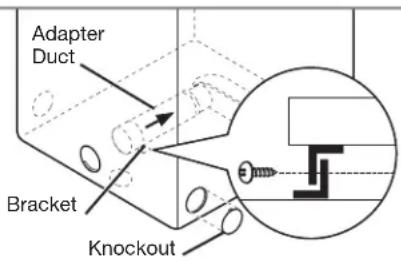
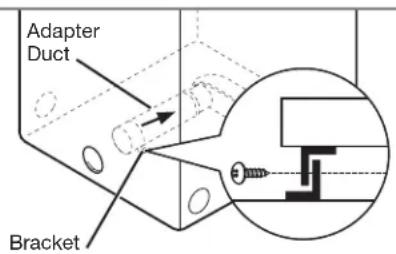
Adapter Duct Bracket Knockout2 Press the tabs on the knockout and carefully remove the knockout for the desired vent opening (right-side venting is not available on gas models). Press the adapter duct onto the blower housing and secure to the base of the dryer as shown.
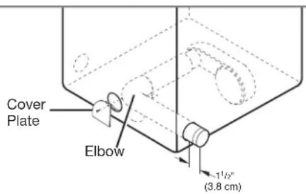
text_image
Cover Plate Elbow 1½" (3.8 cm)3 Preassemble a 4 inches (10.2 cm) elbow to the next 4 inches (10.2 cm) duct section, and secure all joints with duct tape. Be sure that the male end of the elbow faces AWAY from the dryer. Insert the elbow/duct assembly through the side opening and press it onto the adapter duct. Secure in place with duct tape. Be sure that the male end of the duct protrudes 1½ inches (3.8 cm) to connect the remaining ductwork.
Attach cover plate to the back of the dryer with included screw.
text_image
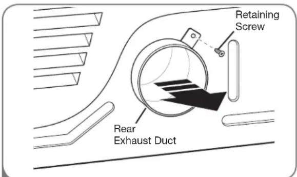
Retaining Screw Rear Exhaust Duct1 Remove the rear exhaust duct retaining screw. Pull out the exhaust duct.
OPTION 2: Bottom Venting
text_image
Adapter Duct Bracket2 Press the adapter duct onto the blower housing and secure to the base of the dryer as shown.
text_image
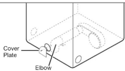
Cover Plate Elbow3 Insert the 4 inches (10.2 cm) elbow through the rear opening and press it onto the adapter duct. Be sure that the male end of the elbow faces down through hole in the bottom of the dryer. Secure in place with duct tape. Attach the cover plate to the back of the dryer with included screw.
VENTING THE DRYER
WARNING:
To reduce the risk of fire, electric shock, or personal injury when using this
appliance, follow basic precautions, including the following:
- Do not crush or collapse ductwork. Failure to follow these instructions can result in fire or death.
- Do not allow ductwork to rest on or contact sharp objects. Failure to follow these instructions can result in fire or death.
- If connecting to existing ductwork, make sure it is suitable and clean before installing the dryer. Failure to follow these instructions can result in fire or death.
- Venting must conform to local building codes. Failure to follow these instructions can result in fire or death.
- Gas dryers MUST exhaust to the outdoors. Failure to follow these instructions can result in fire or death.
- Use only 4-inch (10.2 cm) rigid or flexible metal ductwork inside the dryer cabinet and for venting outside. Failure to follow these instructions can result in fire or death.
- To reduce the risk of fire, combustion, or accumulation of combustible gases, DO NOT exhaust dryer air into an enclosed and unventilated area, such as an attic, wall, ceiling, crawl space, chimney, gas vent, or concealed space of a building. Failure to follow these instructions can result in fire or death.
- To reduce the risk of fire, DO NOT exhaust the dryer with plastic or thin foil ducting. Failure to follow these instructions can result in fire or death.
-
The exhaust duct must be 4 inches (10.2 cm) in diameter with no obstructions. The exhaust duct should be kept as short as possible. Make sure to clean any old ducts before installing your new dryer. Failure to follow these instructions can result in fire or death.
-
Rigid or semirigid metal ducting is recommended for use between the dryer and the wall. In special installations when it is impossible to make a connection with the above recommendations, a UL-listed flexible metal transition duct may be used between the dryer and wall connection only. The use of this ducting will affect drying time. Failure to follow these instructions can result in fire or death.
- DO NOT use sheet metal screws or other fasteners which extend into the duct that could catch lint and reduce the efficiency of the exhaust system. Secure all joints with duct tape. Failure to follow these instructions can result in fire or death.
- To maximize operating results, please observe the duct length limitations noted in the chart on page 17. Failure to follow these instructions can result in fire or death.
- Ductwork is not provided with the dryer. You should obtain the necessary ductwork locally. The end cap should have hinged dampers to prevent backdraft when the dryer is not in use. Failure to follow these instructions can result in fire or death.
- The Total length of flexible metal duct shall not exceed 8 ft. (2.4m)
- In Canada, that only those foil-type flexible ducts, if any, specifically identified for use with the appliance by the manufacturer shall be used. In the United States, that only those foil-type flexible ducts, if any, specifically identified for use with the appliance by the manufacturer and that comply with the Outline for Clothes Dryer Transition Duct, Subject 2158A, shall be used.
VENTING THE DRYER (cont.)
Ductwork
| Wall Cap Type | Number of 90° Elbows | Maximum Length of 4-inch Diameter Rigid Metal Duct |
Recommended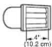 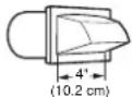 | 0 | 65 ft. (19.8 m) |
| 1 | 55 ft. (16.8 m) | |
| 2 | 47 ft. (13.7 m) | |
| 3 | 36 ft. (11.0 m) | |
| 4 | 28 ft. (8.5 m) | |
Use Only for Short Run Installations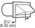 ( ( | 0 | 55 ft. (16.8 m) |
| 1 | 47 ft. (13.7 m) | |
| 2 | 41 ft. (12.5 m) | |
| 3 | 30 ft. (9.1 m) | |
| 4 | 22 ft. (6.7 m) |
NOTE: Deduct 6 ft. (1.8 m) for each additional elbow. It is not recommended to use more than four 90° elbows.
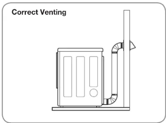
Routing and Connecting Ductwork
Follow the guidelines below to maximize drying performance and reduce lint buildup and condensation in the ductwork.
NOTE: Ductwork and fittings are NOT included and must be purchased separately.
- Use 4-inch (10.2 cm) diameter rigid or semirigid metal ductwork.
- The exhaust duct run should be as short as possible.
- Use as few elbow joints as possible.
- The male end of each section of exhaust duct must point away from the dryer.
- Use duct tape on all duct joints.
- Insulate ductwork that runs through unheated areas in order to reduce condensation and lint buildup on duct surfaces.
IMPORTANT: Failure to exhaust the dryer correctly will void the dryer's warranty.
text_image
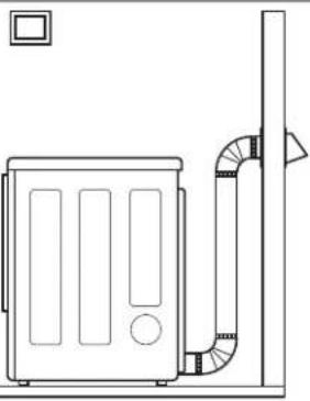
Correct Venting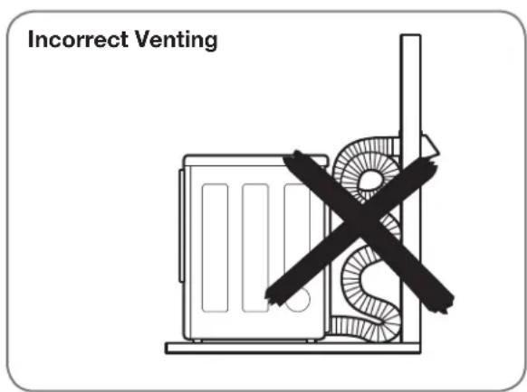
text_image
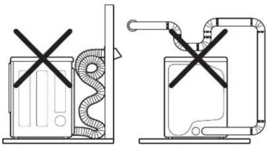
Incorrect VentingCONNECTING GAS DRYERS
WARNING:
To reduce the risk of fire, electric shock, or personal injury when using this
appliance, follow basic precautions, including the following:
• Gas supply requirements:
As shipped from the factory, this dryer is configured for use with natural gas. It can be converted for use with LP (Liquefied Propane) gas. Gas pressure must not exceed 13 inches of water column.
- A qualified service or gas company technician must connect the dryer to the gas service. Failure to do so can result in fire, explosion, or death.
- Isolate the dryer from the gas supply system by closing its individual manual shutoff valve during any pressure testing of the gas supply. Failure to do so can result in fire, explosion, or death.
• Supply line requirements:
Your laundry room must have a rigid gas supply line to your dryer. In the United States, an individual manual shutoff valve MUST be installed within at least 6 ft. (1.8 m) of the dryer, in accordance with the National Fuel Gas Code ANSI Z223.1 or Canadian gas installation code CSA B149.1. A 18 -inch NPT pipe plug must be installed. Failure to do so can result in fire, explosion, or death
- If using a rigid pipe, the rigid pipe should be 12 - inch IPS. If acceptable under local codes and ordinances and when acceptable to your gas supplier, 38 - inch approved tubing may be used where lengths are less than 20 ft. (6.1 m). Larger tubing should be used for lengths in excess of 20 ft. (6.1 m). Failure to do so can result in fire, explosion, or death.
- Connect the dryer to the type of gas shown on the nameplate. Failure to do so can result in fire, explosion, or death.
- To prevent contamination of the gas valve, purge the gas supply of air and sediment before connecting the gas supply to the dryer. Before tightening the connection between the gas supply and the dryer, purge remaining air until the odor of gas is detected. Failure to do so can result in fire, explosion, or death.
- DO NOT use an open flame to inspect for gas leaks. Use a noncorrosive leak-detection fluid. Failure to do so can result in fire, explosion, or death.
- Use only a new AGA- or CSA-certified gas supply line with flexible stainless steel connectors. Failure to do so can result in fire, explosion, or death.
- Securely tighten all gas connections. Failure to do so can result in fire, explosion, or death.
- Use a pipe-joint compound that is insoluble in Liquefied Petroleum (LP) gas on all pipe threads. Failure to do so can result in fire, explosion, or death.
- DO NOT attempt any disassembly of the dryer; any disassembly requires the attention and tools of an authorized and qualified service person or company. Failure to do so can result in fire, explosion, or death.
Electrical Requirements for Gas Models Only
WARNING:
To reduce the risk of fire, electric shock, or personal injury when using this
appliance, follow basic precautions, including the following:
- Do not, under any circumstances, cut or remove the third (ground) prong from the power cord. Failure to follow this warning can result in fire, explosion, or death.
- For personal safety, this dryer must be properly grounded. Failure to follow this warning can result in fire, explosion, or death.
-
The power cord of this dryer is equipped with a 3-prong (grounding) plug which mates with a standard 3-prong (grounding) wall outlet to minimize the possibility of electric shock hazard from this appliance. Failure to follow this warning can result in fire, explosion, or death.
-
This dryer must be plugged into a 20 A, 120 VAC. grounded outlet protected by a 15-ampere fuse or circuit breaker. Failure to follow this warning can result in fire, explosion, or death.
- Where a standard 2-prong wall outlet is encountered, it is your personal responsibility and obligation to have it replaced with a properly grounded 3-prong wall outlet. Failure to follow this warning can result in fire, explosion, or death.
CONNECTING GAS DRYERS (cont.)
WARNING:
To reduce the risk of fire, electric shock, or personal injury when using this appliance, follow basic precautions, including the following:
- Installation and service must be performed by a qualified installer, service agency, or the gas supplier. Failure to do so can result in fire, explosion, or death.
- Use only a new stainless steel flexible connector and a new AGA-certified connector. Failure to do so can result in fire, explosion, or death.
- A gas shutoff valve must be installed within 6 ft. (1.8 m) of the dryer. Failure to do so can result in fire, explosion, or death.
-
The dryer is configured for Natural Gas when shipped from the factory. Make sure that the dryer is equipped with the correct burner orifice for the type of gas being used (Natural Gas or Liquefied Petroleum). Failure to do so can result in fire, explosion, or death.
-
If necessary, the correct orifice (for the LP orifice kit order part number 383EEL3002D) should be installed by a qualified technician and the change should be noted on the dryer.
Failure to do so can result in fire, explosion, or death. - All connections must be in accordance with local codes and regulations. Failure to do so can result in fire, explosion, or death.
- Gas dryers MUST exhaust to the outdoors. Failure to do so can result in fire, explosion, or death.
Connecting the Gas Supply
1 Make sure that the gas supply to the laundry room is turned OFF. Confirm that the type of gas available in your laundry room is appropriate for the dryer. The dryer is prepared for Natural Gas with a 38 -inch NPT gas connection.
2 Remove the shipping cap from the gas connection at the back of the dryer. Be careful not to damage the threads of the gas connector when removing the shipping cap.
3 Connect the dryer to your laundry room's gas supply using a new flexible stainless steel connector with a 3 / 8 - inch NPT fitting.
4 Securely tighten all connections between the dryer and your laundry room's gas supply. Turn on your laundry room's gas supply and check all pipe connections (both internal and external) for gas leaks with a noncorrosive leak-detection fluid.
Electrical Connection
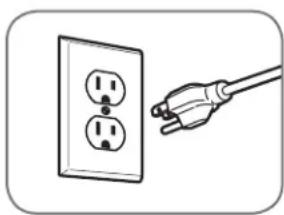
natural_image
Illustration of a hand holding an electrical outlet with two outlets (no text or symbols)Plug dryer into a 120 VAC, 60 Hz grounded 3-prong outlet.
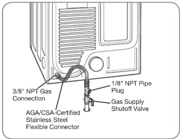
text_image
3/8" NPT Gas Connection 1/8" NPT Pipe Plug AGA/CSA-Certified Stainless Steel Flexible Connector Gas Supply Shutoff ValveHigh-Altitude Installations
The BTU rating of this dryer is AGA-certified for elevations below 10,000 feet.
If your gas dryer is being installed at an elevation above 10,000 feet, it must be derated by a qualified technician or gas supplier.
CONNECTING ELECTRIC DRYERS
WARNING:
To help prevent fire, electric shock, serious injury, or death, the wiring and grounding must conform to the latest edition of the National Electrical Code, ANSI/NFPA 70 and all applicable local regulations. Please contact a qualified electrician to check your home's wiring and fuses to ensure that your home has adequate electrical power to operate the dryer.
Electrical Requirements for Electric Models Only
WARNING:
To reduce the risk of fire, electric shock, or personal injury when using this appliance, follow basic precautions, including the following:
- This dryer must be connected to a grounded metal, permanent wiring system, or an equipment-grounding conductor must be run with the circuit conductors and connected to the equipment-grounding terminal or lead on the dryer. Failure to do so can result in fire, explosion, or death.
- The dryer has its own terminal block that must be connected to a separate 240 VAC, 60-Hertz, single-phase circuit, fused at 30 amperes (the circuit must be fused on both sides of the line). ELECTRICAL SERVICE FOR THE DRYER SHOULD BE OF THE MAXIMUM RATE VOLTAGE LISTED ON THE NAMEPLATE. DO NOT CONNECT DRYER TO 110-, 115-, OR 120-VOLT CIRCUIT. Failure to follow these instructions can result in fire, explosion, or death.
- If branch circuit to dryer is 15 ft. (4.5 m) or less in length, use UL (Underwriters Laboratories) listed No.-10 AWG wire
(copper wire only), or as required by local codes. If over 15 ft. (4.50 m), use UL-listed No.-8 AWG wire (copper wire only), or as required by local codes. Allow sufficient slack in wiring so dryer can be moved from its normal location when necessary. Failure to do so can result in fire, explosion, or death.
- The power cord (pigtail) connection between wall receptacle and dryer terminal block IS NOT supplied with dryer. Type of pigtail and gauge of wire must conform to local codes and with instructions on the following pages. Failure to follow these instructions can result in fire, explosion, or death.
- A 4-wire connection is required for all mobile and manufactured home installations, as well as all new construction after January 1, 1996. A 4-wire connection must be used where local codes do not permit grounding through the neutral wire. Failure to do so can result in fire, explosion, or death.
WARNING:
To reduce the risk of fire, electric shock, or personal injury when using this appliance, follow basic precautions, including the following:
- Do not modify the plug and internal wire provided with the dryer.
- The dryer should be connected to 4-hole outlet.
- If it does not fit the outlet, a proper outlet will need to be installed by a qualified electrician.
Special Electrical Requirements for Mobile or Manufactured Homes
WARNING:
To reduce the risk of fire, electric shock, or personal injury when using this appliance, follow basic precautions, including the following:
- Any installation in a manufactured or mobile home must comply with the Manufactured Home Construction and Safety Standards Title 24 CFR, Part 32-80 or Standard CAN/CSA0Z240 MH and local codes and ordinances.
- A 4-wire connection is required for all mobile and manufactured home installations, as well as all new construction after January 1, 1996. Failure to do so can result in fire, explosion, or death.
CONNECTING ELECTRIC DRYERS (cont.)
USA ONLY
WARNING:
- Connect the power cord to the terminal block. Each colored wire should be connected to same color screw. Wire color indicated on manual is connected to the same color screw in block. Failure to follow these instructions may result in a short or overload.
- Grounding through the neutral conductor is prohibited for: (1) new branch-circuit installations, (2) mobile homes, (3) recreational vehicles, and (4) areas where local codes prohibit grounding through the neutral conductor.

Four-Wire Connection for Electric Dryers: Power Cord
- A 4-wire connection is required for all mobile and manufactured home installations, as well as all new construction after January 1, 1996.
- A UL-listed strain relief is required.
- Use a 30 A, 240 V, UL-listed power cord with #10 AWG-minimum copper conductor and closed loop or forked terminals with upturned ends.
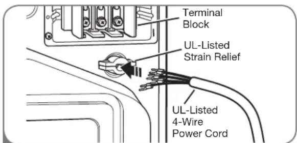
text_image
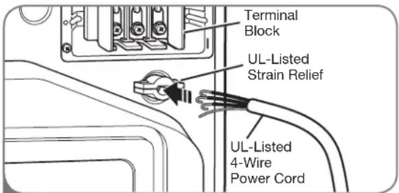
Terminal Block UL-Listed Strain Relief UL-Listed 4-Wire Power Cord1 Remove the terminal block access cover on the upper back of the dryer. Install a UL-listed strain relief into the power cord through-hole; then thread a UL-listed, 30 A, 240 V, 4-wire, #10 AWG-minimum copper conductor power cord through the strain relief.
text_image
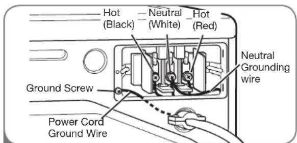
Hot (Black) Neutral (White) Hot (Red) Ground Screw Power Cord Ground Wire Neutral Grounding wire2 Transfer the dryer's ground wire from behind the green ground screw to the center screw of the terminal block. Attach the two hot leads of the power cord to the outer terminal block screws. Attach the white neutral wire to the center terminal block screw. Attach the power cord ground wire to the green ground screw. TIGHTEN ALL SCREWS SECURELY. Reinstall the terminal block access cover.
CONNECTING ELECTRIC DRYERS (cont.)
USA ONLY
WARNING:
- Connect the power cord to the terminal block. Each colored wire should be connected to same color screw. Wire color indicated on manual is connected to the same color screw in block. Failure to follow these instructions may result in a short or overload.
- Grounding through the neutral conductor is prohibited for: (1) new branch-circuit installations, (2) mobile homes, (3) recreational vehicles, and (4) areas where local codes prohibit grounding through the neutral conductor.
Four-Wire Connection for Electric Dryers: Direct Wire
- A 4-wire connection is required for all mobile and manufactured home installations, as well as all new construction after January 1, 1996.
- A UL-listed strain relief is required.
text_image
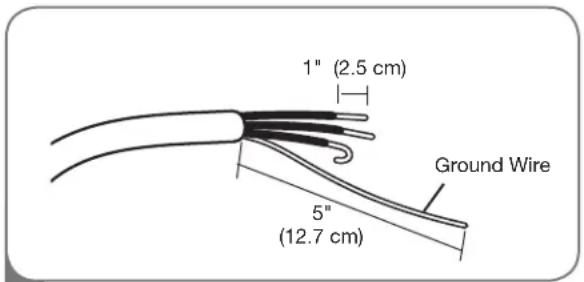
1" (2.5 cm) 5" (12.7 cm) Ground Wire1 Remove 5 inches (12.7 cm) of the outer covering from the wire. Remove 5 inches of insulation from the ground wire. Cut off approximately 112 inches (3.8 cm) from the other three wires and strip 1 inch (2.5 cm) insulation from each wire. Bend the ends of the three shorter wires into a hook shape.
text_image
Terminal Block UL-Listed Strain Relief UL-Listed 4-Wire Power Cord2 Remove the terminal block access cover on the upper back of the dryer. Install a UL-listed strain relief into the power cord through-hole; then thread the power cable prepared in Step 1 through the strain relief.
- Use UL-listed 4-wire #10 AWG-minimum copper conductor cable.
- Allow at least 5 ft. (1.5 m) length to allow for removal and reinstallation of the dryer.
text_image
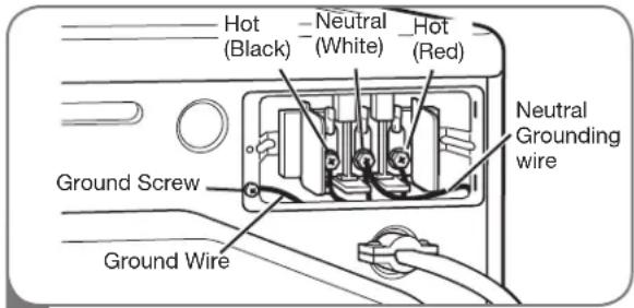
Hot (Black) Neutral (White) Hot (Red) Ground Screw Ground Wire Neutral Grounding wire3 Transfer the dryer's ground wire from behind the green ground screw to the center screw of the terminal block. Attach the two hot leads of the power cable to the outer terminal block screws. Attach the white neutral wire to the center terminal block screw. Attach the power cable ground wire to the green ground screw. TIGHTEN ALL SCREWS SECURELY. Reinstall the terminal block access cover.
CONNECTING ELECTRIC DRYERS (cont.)
USA ONLY
WARNING:
- Connect the power cord to the terminal block. Each colored wire should be connected to same color screw. Wire color indicated on manual is connected to the same color screw in block. Failure to follow these instructions may result in a short or overload.
- Grounding through the neutral conductor is prohibited for: (1) new branch-circuit installations, (2) mobile homes, (3) recreational vehicles, and (4) areas where local codes prohibit grounding through the neutral conductor.

Three-Wire Connection for Electric Dryers: Power Cord
- A 3-wire connection is NOT permitted on new construction after January 1, 1996.
- A UL-listed strain relief is required.
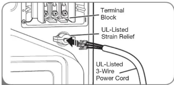
text_image
Terminal Block UL-Listed Strain Relief UL-Listed 3-Wire Power Cord1
Remove the terminal block access cover on the upper back of the dryer. Install a UL-listed strain relief into the power cord through-hole; then thread a UL-listed, 30 A, 240 V, 3-wire, #10 AWG-minimum copper conductor power cord through the strain relief.
- Use a 30 A, 240 V, UL-listed power cord with #10 AWG-minimum copper conductor and closed loop or forked terminals with upturned ends.

text_image
Hot (Black) Neutral (White) Hot (Red) Ground Screw Neutral Grounding wire ound Wire2
Attach the two hot leads of the power cord to the outer terminal block screws. Attach the neutral wire to the center terminal block screw. Connect the external ground (if required by local codes) to the green ground screw. TIGHTEN ALL SCREWS SECURELY. Reinstall the terminal block access cover.
CONNECTING ELECTRIC DRYERS (cont.)
USA ONLY
WARNING:
- Connect the power cord to the terminal block. Each colored wire should be connected to same color screw. Wire color indicated on manual is connected to the same color screw in block. Failure to follow these instructions may result in a short or overload.
- Grounding through the neutral conductor is prohibited for: (1) new branch-circuit installations, (2) mobile homes, (3) recreational vehicles, and (4) areas where local codes prohibit grounding through the neutral conductor.
Three-Wire Connection for Electric Dryers: Direct Wire
- A 3-wire connection is NOT permitted on new construction after January 1, 1996.
- A UL-listed strain relief is required.
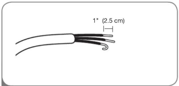
text_image
1" (2.5 cm)1 Remove 3½ inches (8.9 cm) of the outer covering from the wire. Strip 1 inch (2.5 cm) insulation from each wire. Bend the ends of the three wires into a hook shape.
- Use UL-listed 3-wire #10 AWG-minimum copper conductor cable.
- Allow at least 5 ft. (1.5 m) length to allow for removal and reinstallation of the dryer.
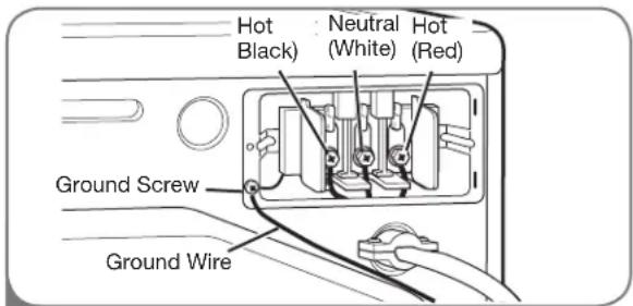
text_image
Hot Black) Neutral (White) Hot (Red) Ground Screw Ground Wire3 Attach the two hot leads of the power cord to the outer terminal block screws. Attach the neutral wire to the center terminal block screw. Connect the external ground (if required by local codes) to the green ground screw. TIGHTEN ALL SCREWS SECURELY. Reinstall the terminal block access cover.
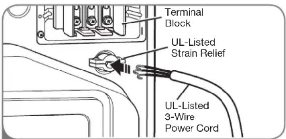
text_image
Terminal Block UL-Listed Strain Relief UL-Listed 3-Wire Power Cord2 Remove the terminal block access cover on the upper back of the dryer. Install a UL-listed strain relief into the power cord through-hole; then thread the power cable prepared in Step 1 through the strain relief.
SPECIAL REQUIREMENTS FOR MANUFACTURED OR MOBILE HOMES
Any installation in a manufactured or mobile home must comply with the Manufactured Home Construction and Safety Standards Title 24 CFR, Part 32-80 or Standard CAN/CSA0Z240 MH and local codes and ordinances. If you are uncertain whether your proposed installation will comply with these standards, please contact a service and installation professional for assistance.
- A gas dryer must be permanently attached to the floor.
- The electrical connection for an electric dryer must be a 4-wire connection. More detailed information concerning the electrical connection is provided in the section Connecting Electric Dryers.
- To reduce the risk of combustion and fire, the dryer must be vented to the outside.
- DO NOT vent the dryer under a manufactured home or mobile home.
- Electric dryers may be vented to the outside using the back, left, right, or bottom panel.
-
Gas dryers may be vented to the outside using the back, left, or bottom panel. Gas dryers may not be vented to the outside using the right side panel because of the burner housing.
-
The dryer exhaust duct must be affixed securely to the manufactured or mobile home structure, and the exhaust duct must be made of a material that will resist fire and combustion. It is recommended that you use a rigid or flexible metal duct.
- DO NOT connect the dryer exhaust duct to any other duct, vent, chimney, or other exhaust duct.
- Make sure the dryer has adequate access to outside fresh air to ensure proper operation. The opening for outside fresh air must be at least 25in^2 (163 cm²).
- It is important that the clearance of the duct from any combustible construction be at least 2 inches (5 cm), and when venting the dryer to the outdoors, the dryer can be installed with a clearance of 1 inch (2.5 cm) at the sides and back of the dryer.
- Please be aware that venting materials are not supplied with the dryer. You should obtain the venting materials necessary for proper installation.
FINAL INSTALLATION CHECK
Once you have completed the installation of the dryer and it is in its final location, confirm proper operation with the following tests and Duct Condition Testing on the following page.
Testing Dryer Heating
GAS MODELS
Close the dryer door, press the ON/OFF switch to turn the dryer on, and start the dryer on a heat setting. When the dryer starts, the igniter should ignite the main burner.
NOTE: If all air is not purged from the gas line, the gas igniter may turn off before the main burner ignites. If this happens, the igniter will reattempt gas ignition after approximately two minutes.
ELECTRIC MODELS
Close the dryer door, press the ON/OFF switch to turn the dryer on, and start the dryer on a heat setting. The exhaust air should be warm after the dryer has been operating for 3 minutes.
Checking Airflow
Effective dryer operation requires proper airflow. The adequacy of the airflow can be measured by evaluating the static pressure. Static pressure in the exhaust duct can be measured with a manometer, placed on the exhaust duct approximately 2 ft. (60.9 cm) from the dryer. Static pressure in the exhaust duct should not exceed 0.6 inches (1.5 cm). The dryer should be checked while the dryer is running with no load.
Checking Levelness
Once the dryer is in its final location, recheck the dryer to be sure it is level. Make sure it is level front to back and side to side, and that all 4 leveling feet are firmly on the floor.
DUCT CONDITION TEST
Your dryer features FlowSense™, an innovative sensing system that automatically detects blockages and restrictions in dryer ductwork. Keeping ductwork clean of lint buildup and free of restrictions allows clothes to dry faster and reduces energy use.
NOTE: When the dryer is first installed, this test should be performed to alert you to any existing problems with the exhaust duct in your home. However, since the test performed during normal operation provides more accurate information on the condition of the exhaust duct than does the installation test, the number of bars displayed during the two tests may not be the same.
To activate the duct condition test :
NOTE: Dryer heating test must be performed before proceeding. Then perform the duct condition test below:
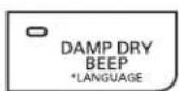
1 Press and hold the DAMP DRY BEEP and TEMP.CONTROL buttons at the same time. While holding these buttons, press POWER ON/OFF.


2 The display will show the FLOW CHECK start screen.


Press START/PAUSE. The dryer will run for approximately 2 minutes to test for blockages or restrictions to air flow in the ductwork.

text_image
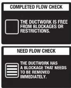
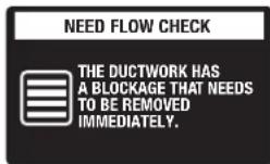
COMPLETED FLOW CHECK THE DUCTWORK IS FREE FROM BLOCKAGES OR RESTRICTIONS. NEED FLOW CHECK THE DUCTWORK HAS A BLOCKAGE THAT NEEDS TO BE REMOVED IMMEDIATELY.If no bars are shown in the display, the ductwork is free from blockages or restrictions.
If all bars are lit, the dryer ductwork has a blockage that needs to be removed immediately.
IMPORTANT: Do NOT interrupt the test cycle!
NOTE : Even if no bars are displayed during the duct condition test, some restrictions may still be present in the exhaust dust. Refer to pages 14-15 for more information.
Correct Venting
natural_image
Line drawing of a mechanical or electrical component with a vertical pipe and rectangular panel (no text or symbols)Restricted or Blocked Airflow

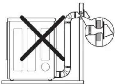
Avoid long runs or runs with multiple elbows or bends.
natural_image
Two schematic diagrams of industrial equipment with no visible text, numbers, or symbols.Check for blockages and lint buildup.
text_image
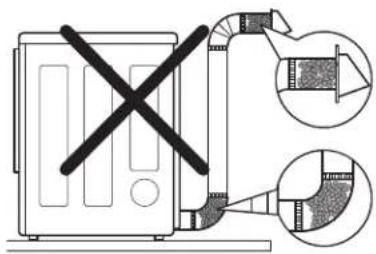
Diagram showing a device with a cross mark and two close-up insets illustrating internal components or sections.Make sure the ductwork is not crushed or restricted.
natural_image
Diagram of a mechanical device with a cross mark and a magnified inset showing internal components (no text or symbols)CONTROL PANEL FEATURES
Following are instructions for starting and using your new dryer. Please refer to specific sections of this manual for more detailed information.
Important Warning: To reduce the risk of fire, electric shock, or personal injury, read this entire manual, including the Important Safety Instructions, before operating this dryer.
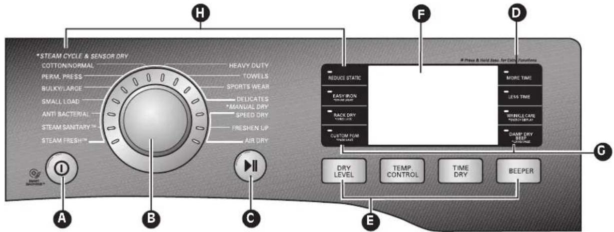
text_image
*STEAM CYCLE & SENSOR DRY COTTON/NORMAL HEAVY DUTY PERM. PRESS TOWELS BULKYLARGE SPORTS WEAR SMALL LOAD DELICATES ANTI BACTERIAL *MANUAL DRY STEAM SANITARY SPEED DRY STEAM FRESH FRESH FRESH UP FRESHEN UP AIR DRY I II A B C #Press & Hold less for Data Transformers REDUCE STATIC MORE TIME EASY IRON TIME/LEAST RACK DRY TIME/LEAST CUSTOM PET WM/LEAST MORE TIME LESS TIME DRINK CASE DRINK SET/UP DAMP DRY KEEP REDUCE/LEAST DRY LEVEL TEMP. CONTROL TIME DRY BEEPERA POWER ON/OFF BUTTON
Press to turn the dryer ON. Press again to turn the dryer OFF.
NOTE: Pressing the ON/OFF button during a cycle will cancel that cycle and any load settings will be lost.
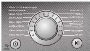
B CYCLE SELECTOR KNOB
Turn this knob to select the desired cycle. Once the desired cycle has been selected, the standard presets will be shown in the display. On MANUAL DRY cycles, these settings can be adjusted using the cycle settings buttons anytime.
© START/PAUSE BUTTON
Press this button to START the selected cycle. If the dryer is running, use this button to PAUSE the cycle without losing the current settings.
NOTE: If you do not press the START/PAUSE button to resume a cycle within 4 minutes, the dryer automatically turns off.
D MORE TIME/LESS TIME BUTTONS
To adjust the drying time, use these buttons with MANUAL DRY, TIME DRY, and STEAMFRESH™ cycles, as well as the REDUCE STATIC and EASY IRON options. Press the MORE TIME button to increase the selected manual cycle time by a minute; press LESS TIME to decrease the cycle time by a minute.
E CYCLE SETTING BUTTONS
Use these buttons to select the desired cycle settings for the selected cycle. The current settings are shown in the display. Press the button for that option to view and select other settings.
F LCD DISPLAY
The display shows the settings, estimated time remaining, options, and status messages for your dryer.
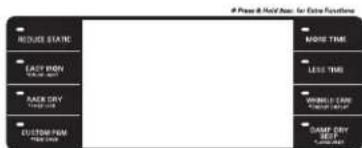
OPTION BUTTONS
The OPTION buttons allow you to select additional cycle options. Certain buttons feature a special function (see the following pages for details) that can be activated by pressing and holding that option button.
H STEAM FUNCTIONS
LG's steam technology allows you to inject fabrics with a swirling jet of hot steam to refresh clothes, reduce static, and make ironing easier. Simply select the STEAMFRESH™ cycle, or you can add a STEAM option to selected cycles.
For detailed information about the individual options, please see the following pages.
OPERATING THE DRYER
natural_image
Cross-sectional diagram of a mechanical device showing internal components and housing (no text or labels)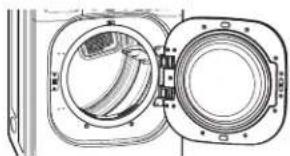
natural_image
Cross-sectional diagram of a mechanical device showing internal components (no text or labels)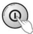
text_image
STREAM CYCLE & SUNDAY TWO/SPRING TRAVEL SPRING WEAR TRAVEL SPRING TRAVEL TRAVEL TRAVEL TRAVEL TRAVEL TRAVEL TRAVEL TRAVEL TRAVEL TRAVEL TRAVEL TRAVEL TRAVEL TRAVEL TRAVEL TRAVEL TRAVEL TRAVEL TRAVEL TRAVEL TRAVEL TRAVEL TRAVEL TRAVEL TRAVEL TRAVELL ON TRAVELL ON TRAVELL ON TRAVELL ON TRAVELL ON TRAVELL ON TRAVELL ON TRAVELL ON TRAVELL ON TRAVELL ON TRAVELL ON TRAVELL ON TRAVELL ON TRAVELL ON TRAVELL ON TRAVELL ON TRAVELL ON TRAVELL ON TRAVELL ON TRAVELL ON TRAVELL On TRAVELL On TRAVELL On TRAVELL On TRAVELL On TRAVELL On TRAVELL On TRAVELL On TRAVELL On TRAVELL On TRAVELL On TRAVELL On TRAVELL On TRAVELL On TRAVELL On TRAVELL On TRAVELL On TRAVELL On TRAVELL On TRAVELL On TRAVELL Off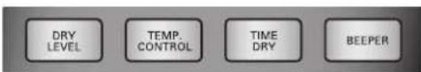
text_image
Press & Hold Name: For Extra Functions
REDUCE STATIC EASY IRON EASY IRON RACE DRY CUSTOM PAM EASY IRON EASY IRON EASY IRON EASY IRON EASY IRON EASY IRON EASY IRON EASY IRON EASY IRON EASY IRON EASY IRON EASY IRON EASY IRON EASY IRON EASY IRON EASY IRON EASY IRON EASY IRON EASY IRON EASY IRON EASY IRONE

① CLEAN THE LINT FILTER
If the lint filter has not already been cleaned, lift out the filter and remove the lint from the last load. This will help ensure the fastest and most efficient drying performance.
② LOAD THE DRYER
Load the dryer with the wet laundry from the washer. If the load is extra large, you may need to divide it into smaller loads for proper performance and fabric care.
3 TURN ON THE DRYER
Press the POWER button to turn on the dryer. The cycle LEDs will illuminate and a beep will sound, if turned on. Refer to page 27.
4 SELECT A CYCLE
Turn the Cycle Selector Knob either direction until the LED for the desired cycle is on. The preset temperature, dry level, and option settings for that cycle will be shown. Refer to page 29.
5 SELECT CYCLE MODIFIERS
Default settings for the selected cycle can now be changed if desired. This can be done using the cycle modifier buttons as shown on page 33 (temperature, dry level, and beep).
NOTE: Not all options or modifiers are available on all cycles. A different chime will sound and the LED will not come on if the selection is not allowed.
6 SELECT CYCLE OPTIONS
Cycle options can be added using the option buttons as shown on page 33-34 (reduce static, easy iron, drum light, rack dry, child lock, wrinkle care and damp dry beep).
NOTE: Not all options or modifiers are available on all cycles. A different chime will sound and the LED.
7 BEGIN CYCLE
Press the START/PAUSE button to begin the cycle. The cycle can be paused at any time either by opening the door or by pressing the START/PAUSE button. If the cycle is not restarted within 4 minutes, the dryer will shut off and the cycle settings will be lost.
8 END OF CYCLE
When the cycle is finished, the chime will sound if it is set. Remove your clothing from the dryer immediately to reduce wrinkling. If Wrinkle care is selected, the dryer will tumble briefly every few minutes to help prevent wrinkles from setting in the clothes.
CYCLE GUIDE
The cycle guide below shows the options and recommended fabric types for each cycle.
| Type | Cycle | Fabric Type | Dry Level | Temperature | Time in Min. | More Time/ Less Time | Wrinkle Care | Damp Dry Beep | Reduce Static | Easy Iron |
| STEAM CYCLE / SENSOR DRY | STEAM FRESHTM | Comforter, Shirts, Trouser (except especially delicate fabrics) | Off | MEDIUM HIGH | 20 | |||||
| STEAM SANITARYTM | Comforter, Bedding, Children' clothing | Off | HIGH | 39 | ||||||
| ANTIBACTERIAL | Do not use this cycle with delicate fabrics. | Very Dry | HIGH | 70 | ||||||
| BULKY/LARGE | Cormforters, Pillows, shirt | Normal | MEDIUM | 55 | ||||||
| Adjustable | ||||||||||
| SMALL LOAD | Only Normal & Cotton/Towels Fabric Type (Max 3lb) | Normal | HIGH | 30 | ||||||
| Adjustable | ||||||||||
| PERM. PRESS | Permanent press, synthetic items | Normal | LOW | 32 | ||||||
| Adjustable | ||||||||||
| COTTON/NORMAL | Work clothes, corduroys, etc. | Normal | MEDIUM 41 | |||||||
| Adjustable | ||||||||||
| HEAVY DUTY | Jeans, heavyweight items | Normal | HIGH | 54 | ||||||
| Adjustable | ||||||||||
| TOWELS | Denims, towels, heavy cottons | Normal | MEDIUM HIGH | 55 | ||||||
| Adjustable | ||||||||||
| SPORTS WEAR | Sports wear | Off | - | 27 | ||||||
| DELICATES | Lingerie, sheets, blouses | Normal | LOW | 28 | ||||||
| Adjustable | ||||||||||
| MANUAL DRY | SPEED DRY | For small loads with short drying times | Off | HIGH | 15 | |||||
| Adjustable | Adjustable | |||||||||
| FRESHEN UP | For removing light wrinkles from clothing | Off | MEDIUM HIGH | 20 | ||||||
| Adjustable | Adjustable | |||||||||
| AIR DRY | For items that require heat-free drying such as plastics or rubber | Off | NO | 30 | ||||||
| HEAT | Adjustable |
Sensor Dry Cycles
Sensor Dry cycles utilize LG's unique dual sensor system to detect and compare the moisture level in clothes and in the air and adjust the drying time as needed to ensure superior results. The dryer automatically sets the dryness level and temperature at the recommended setting for each cycle. The estimated time remaining will be shown in the display.
NOTE:
To protect your garments not every dryness level, temperature, or option is available with every cycle. See the Cycle Guide for details.
Manual Dry Cycles
Use Manual Dry cycles to select a specific amount of drying time and a drying temperature. When a Manual Dry cycle is selected, the ESTIMATED TIME REMAINING display shows the actual time remaining in your cycle. You can change the actual time in the cycle by pressing MORE TIME or LESS TIME.

Certified by NSF
NSF International (formerly the National Sanitation Foundation), certifies that ANTI BACTERIAL Cycle reduces 99.9% of bacteria on laundry, and none of bacteria will carry over onto the next laundry load.
Following are instructions for starting and using your new dryer. Please refer to specific sections of this manual for more detailed information. Important Warning: To reduce the risk of fire, electric shock, or personal injury, read this entire manual, including the Important Safety Instructions, before operating this dryer.
SORTING LOADS
Fabric Care Labels
Most articles of clothing feature fabric care labels that include instructions for proper care.
Fabric Care Labels
Tumble dry

Dry

Normal

Permanent Press/ wrinkle resistant

Gentle/ delicate

Do not tumble dry

Do not dry (used with do not wash)
Heat setting

High

Medium

Low

No heat/air
Grouping Similar Items
For best results, sort clothes into loads that can be dried with the same drying cycle. Different fabrics have different care requirements, and some fabrics will dry more quickly than others.
LOADING THE DRYER
WARNING:
To reduce the risk of fire, electric shock, or injury to persons when using this appliance, follow basic precautions, including the following:
- Check all pockets to make sure that they are empty. Items such as clips, pens, coins, and keys can damage both your dryer and your clothes. Flammable objects such as lighters or matches could ignite, causing a fire.
Failure to do so can result in fire, explosion, or death. - Never dry clothes that have been exposed to oil, gasoline, or other flammable substances. Washing clothes will not completely remove oil residues. Failure to obey this warning can result in fire, explosion, or death.
Loading Tips
- Combine large and small items in a load.
- Damp clothes will expand as they dry. Do not overload the dryer; clothes require room to tumble dry properly.
- Close zippers, hooks, and drawstrings to prevent these items from snagging or tangling on other clothes.
CHECK THE LINT FILTER BEFORE EVERY LOAD
Always make sure the lint filter is clean before starting a new load; a clogged lint filter will increase drying times.
To clean, pull the lint filter straight up and roll any lint off the filter with your fingers. Do not rinse or wash the filter to remove lint. Push the lint filter firmly back into place. See Regular Cleaning (Page 38) for more information.
Always ensure the lint filter is properly installed before running the dryer. Running the dryer with a loose or missing lint filter may damage the dryer and articles in the dryer.
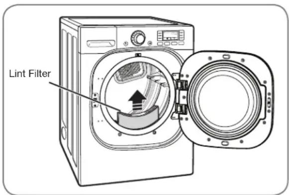
text_image
Lint FilterTHE LCD DISPLAY
The display shows the settings, estimated time remaining, options, and status messages for your dryer. When the dryer is turned on, the light in the display will illuminate.
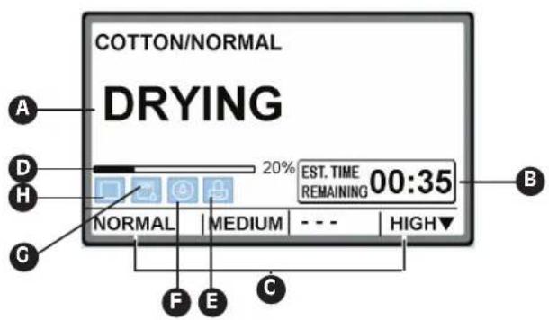
text_image
COTTON/NORMAL DRYING A D H G 20% EST. TIME 00:35 REMAINING NORMAL MEDIUM HIGH▼ F E CA STATUS/CYCLE DISPLAY
This portion of the display shows the selected cycle, operating status, and special messages. If a cycle has special instructions, they will also be displayed in this area.
B ESTIMATED TIME REMAINING
When the START/PAUSE button is pressed, the dryer will display the estimated (SENSOR DRY) or set time (TIME DRY) remaining, and begin tumbling.
NOTE: The cycle time on SENSOR DRY cycles may fluctuate as the dryer recalculates drying time for optimal results.
© CYCLE SETTING INDICATORS
These indicators show the current cycle settings for DRY LEVEL, TEMP. CONTROL, TIME DRY, and BEEPER. To change these settings, press the appropriate settings button.
D CYCLE COMPLETION INDICATOR
Shows how much of the current drying cycle has been completed.
E CHILD LOCK INDICATOR
When CHILD LOCK is set, the Child Lock indicator will appear and all buttons are disabled except the ON/OFF button. This prevents children from changing settings while the dryer is operating.
F DRUM LIGHT INDICATOR
During operating cycle, you can see the drum inside by choosing drum light function. It helps easy viewing the drying cycle.
G ADD WATER INDICATOR
If the steam feeder is lack for water, this indicator will appear. Fill the feeder and restart the cycle.
THE LCD DISPLAY (cont.)
H FLOW SENSE™ DUCT BLOCKAGE SENSING SYSTEM INDICATOR
The FLOW SENSE™ duct blockage sensing system detects and alerts you to blockages in the ductwork that reduce exhaust flow from the dryer. This improves operating efficiency and helps minimize service calls, saving you money.

If no bars are shown in the display, the ductwork is free from blockages.

If two bars in the display are lighted, examine the dryer exhaust system for lint build up or other restrictions, including damage, excess length, foreign objects, etc. See note below.

If all bars are lit, the dryer ductwork has a blockage that needs to be removed immediately.
NOTE: If the duct has been checked and cleaned and two bars are still displayed after several cycles, then there is some restriction in the duct due to length, condition, etc. In this case, no further action is necessary and the dryer can be used normally. However, drying times may be increased and there may be some reduction in operating efficiency
- 2 bars are displayed in the LCD screen.


1. Possible causes
- Ductwork is slightly too long or has too many turns/restrictions.
- Partial blockage of the ductwork due to lint buildup.
2. Solutions
- Install a shorter or straighter duct run. See the Installation Instructions.
- Ductwork should be checked/cleaned soon. Dryer can be used in this condition, but drying times may be longer.
- If END OF CYCLE is displayed after the end of cycle, it will be off in 4 minutes. If POWER button is pressed or the door is opened, power will be off immediately.
- 4 bars are displayed in the LCD screen.

1. Possible causes
- Ductwork is too long or has too many turns/restrictions.
- Significant blockage of the ductwork due to lint buildup or debris.
2. Solutions
- Install a shorter or straighter duct run. See the Installation Instructions.
- Ductwork should be checked/cleaned soon. Dryer can be used in this condition, but drying times may be longer.
- If NEED FLOW CHECK is displayed after the end of cycle, it will be off in 2 hours. If POWER button is pressed or the door is opened, power will be off immediately.
CYCLE SETTING BUTTONS
SENSOR DRY cycles have preset settings that are selected automatically. MANUAL DRY cycles have default settings, but you may also customize the settings using the cycle setting buttons. Press the button for that option to view and select other settings.
NOTE: To protect your garments, not every dryness level, temperature, or option is available with every cycle. See the Cycle Guide for details.
DRY LEVEL

Selects the level of dryness for the cycle. Press the DRY LEVEL button repeatedly to scroll through available settings.
- This option is only available with SENSOR DRY cycles.
- The dryer will automatically adjust the cycle time. Selecting VERY DRY or MORE DRY will increase the cycle time, while LESS DRY or DAMP DRY will decrease the cycle time.
- Use a LESS DRY or DAMP DRY setting for items that you wish to iron.
TEMP. CONTROL

Adjusts the temperature setting from ULTRA LOW to HIGH. This allows precise care of your fabrics
and garments. Press the TEMP. CONTROL button repeatedly to scroll through available settings.
TIME DRY

Allows you to manually select the drying time, from 20 to 60 minutes, in 10-minute increments. Use this for small
loads or to remove wrinkles. Use the MORE TIME/LESS TIME buttons to add or reduce the drying time in 1-minute increments.
BEEPER
Adjusts the volume of the end-of-cycle beeper, or turns off the beeper.
Your dryer features several additional cycle options to customize cycles to meet your individual needs. Certain option buttons also feature a special function (see the following page for details) that can be activated by pressing and holding that option button for 3 seconds.
To Add Cycle Options to a Cycle:
1 Turn on the dryer and turn the cycle selector knob to select the desired cycle.
2 Use the cycle settings buttons to adjust the settings for that cycle.
3 Press the cycle option button(s) for the option you would like to add. A confirmation message will be shown in the display.
4 Press the START/PAUSE button to start the cycle. The dryer will start automatically.
WRINKLE CARE
Selecting this option will tumble the load periodically for up to 3 hours after the selected cycle, or until the door is opened. This is helpful
in preventing wrinkles when you are unable to immediately remove items from the dryer.
DAMP DRY BEEP

With this option, the dryer will beep when the load is approximately 80% dry. This allows you to remove faster-drying lightweight items or items that
you would like to iron or hang while still slightly damp.
RACK DRY
Use RACK DRY with items, such as wool sweaters, silk, and lingerie, that should dry flat. RACK DRY can also be used with items that should not
be tumbled dry, such as gym shoes or stuffed animals. Press RACK DRY button to activate or deactivate the RACK DRY function.
NOTE: NEVER use the rack with a tumble dry cycle.
CYCLE SETTING BUTTONS (cont.)
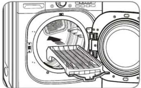
To Install the Drying Rack
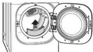
① With the dryer door open, slide the rack into the dryer drum.
natural_image
Line drawing of an open washing machine with internal components and a hand indicating air flow (no text or symbols)2 Make sure it is seated evenly on the edge of the inner door rim and resting flat on the inside of the dryer.
NOTE: Be sure to remove the drying rack after using the RACK DRY cycle.
natural_image
Line drawing of an open refrigerator with internal compartments and ventilation slots (no text or symbols)SPECIAL FUNCTIONS
The option buttons also activate special functions, including CHILD LOCK, DRUM LIGHT, ENERGY UASGE DISPLAY and LANGUAGE. Press and hold the option button marked with the special function for 3 seconds to activate.
\* DRUM LIGHT

Use DRUM LIGHT with item you can see the drum inside by choosing drum light function. It helps easy viewing the drying cycle. Press and hold the
EASY IRON button for 3 seconds to activate or deactivate the DRUM LIGHT function.
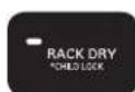
\* CHILD LOCK
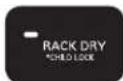
Use this option to prevent unwanted use of the dryer or to keep cycle settings from
being changed while the dryer is operating. Press and hold the RACK DRY button for 3 seconds to activate or deactivate the CHILD LOCK function.
The child lock indicator will be shown in the display, and all buttons are disabled except the ON/OFF button.
NOTE: CHILD LOCK lasts after the end of cycle. If you want to deactivate this function, press and hold the RACK DRY button for 3 seconds.
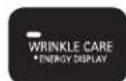
\* ENERGY USAGE DISPLAY

This option provides the electric energy and operating cost for the cycle you selected on the LCD display. The electric charge is converted at
Energy Star's rate. This is a default option. To turn off this option, press and hold the WRINKLE CARE button for 3 seconds. (Estimated operating cost based on a 2007 national average electricity cost of 10.65 cents per kWh and natural gas cost of \$1.218 per therm.)
NOTE: Your cost will depend on your utility rates and use. And the electric energy and operating cost display the default of a cycle.
\* LANGUAGE

You may change the language shown in the display from English to French or Spanish. Press and hold the DAMP DRY BEEP button for 3 seconds until
the display changes. Then select the desired language by pressing the DAMP DRY BEEP button.
Once set, the selected language will remain in memory, even if the Dryer is turned off or unplugged.
CUSTOM PROGRAM

If you have a special combination of settings that you use frequently, you can save these settings as a CUSTOM PROGRAM.
\* To Save a Custom Program:
① Turn on the dryer and turn the cycle selector knob to select the desired cycle.
2 Use the cycle setting buttons to adjust the settings for that cycle.
3 Press the cycle option button(s) for the option you would like to add. A confirmation message will be shown in the display.
4 Press and hold the CUSTOM PROGRAM button for 3 seconds.
STEAM FUNCTIONS
To Fill the Steam Feeder
1 Pull out the drawer.
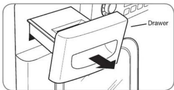
text_image
Drawer2 Lift out the steam feeder.
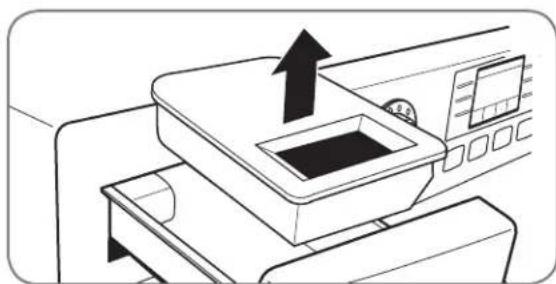
natural_image
Line drawing of a printer with an arrow indicating the process (no text or symbols present)IMPORTANT NOTES ABOUT STEAM CYCLES
Before using a Steam Cycle, the steam feeder must be filled with water up to the MAX line. If not, an Error message or ADD WATER will be displayed. Make sure that the steam feeder is filled with water and the drawer is completely closed. Turn the dryer off then restart the Steam Cycle.
- Only use water. Do not fill the steam feeder with foreign substances, rinse agents, or detergents.
- Before moving the dryer, make sure the steam feeder is empty.
- Do not use distilled water; the water level sensor in the steam generator will not work.
- Be careful to put the Steam Feeder otherwise water will be overflow.
- Wipe up any spilled water around the Steam Feeder and the drawer before starting the dryer.
WARNING:
- Do not fill the steam feeder with liquids such as gasoline, dry-cleaning solvents, or other flammable or explosive substances. They give off vapors that could explode.
- Do not fill the steam feeder with hot water (over 86^ / 30^ ).
- Do not drink water from the steam feeder.
NOTE: You may only save one custom program at a time. Pressing and holding the CUSTOM PROGRAM button will overwrite any previously saved custom program.
To Recall a Custom Program:
① Turn on the dryer.
2 Press the CUSTOM PROGRAM button.
3 Press the START/PAUSE button to start the cycle.
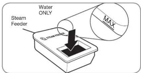
text_image
Steam Feeder Water ONLY MAX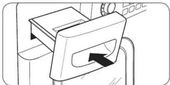
natural_image
Line drawing of a mechanical device with a handle and arrow indicating direction (no text or symbols)3 Fill the steam feeder to MAX with water.
4 Place the steam feeder in the drawer; then push in the drawer until it clicks into place.
STEAM FUNCTIONS (cont.)
LG's new steam technology allows you to inject fabrics with a swirling jet of hot steam to refresh clothes, reduce static, and make ironing easier. Simply select the STEAMFRESH™ cycle, or you can add a Steam option to selected cycles.
Using the STEAMFRESH™ Cycle
STEAMFRESH™ uses the power of steam alone to quickly reduce wrinkles and odor in fabrics. It brings new life to wrinkled clothes that have been stored for an extended time and makes heavily wrinkled clothes easier to iron. STEAMFRESH™ can also be used to help reduce odors in fabrics.
NOTES:
- REDUCE STATIC or EASY IRON options can also be used during the STEAMFRESH™ cycle.
- Depending on the load (quantity of items), you may change the amount of time for the cycle by pressing the MORE TIME or LESS TIME button. The display will show 3, 5, or BULKY LOAD. 3 means 3 or fewer items, 5 is for 4 or 5 items, and BULKY LOAD indicates a large load such as a comforter.
To Use the STEAMFRESH™ Cycle:
1 Turn on the dryer and turn the cycle selector knob to select the STEAMFRESH™ cycle.
2 To add an option function, select REDUCE STATIC, EASY IRON, or WRINKLE CARE.
3 Depending on the load (quantity of items), steam time can be changed by pressing the MORE TIME or LESS TIME buttons.
4 Press START/PAUSE button to start the cycle.
To Add STEAM to a Standard Cycle:
① Turn on the dryer and turn the cycle selector knob to select the desired cycle.
2 Use the cycle setting buttons to adjust the settings for that cycle.
3 Press the Steam option button for the Steam option you would like to add. Then adjust for the load size using the MORE TIME or LESS TIME buttons.
4 Press START/PAUSE button to start the cycle.
Using the Steam Options:

This option injects steam late in the drying cycle to reduce the static electricity caused by dry fabrics rubbing together. Change the amount of time for the cycle by pressing the MORE TIME or LESS TIME button, depending on the load (quantity of items). The display will show the recommended number of items, such as 7, 9, 11, 14, 16, or 18.

The EASY IRON option provides uniform, properly dampened fabrics for ironing, which can save time and make ironing easier. Change the amount of time for the cycle by pressing the MORE TIME or LESS TIME button, depending on the load (quantity of items). The display will show the recommended number of items, such as 1, 2, 3, 4, or 5.
The REDUCE STATIC and EASY IRON options can only be used with the STEAM FRESH ^TM , HEAVY DUTY, PERM.PRESS, COTTON/NORMAL, DELICATES, TOWES, SPEED DRY, FRESHEN UP and TIME DRY cycles.
NOTES:
- When SENSOR DRY is selected with the REDUCE STATIC option, a DRY LEVEL of LESS or DAMP cannot be selected.
- The REDUCE STATIC or EASY IRON option may also be selected during TIME DRY cycles.
- After the Steam option is selected in TIME DRY, the MORE TIME or LESS TIME buttons will change the steam time ONLY.
- After pressing START/PAUSE, the MORE TIME or LESS TIME buttons will be disabled.
Using the STEAMSANITARY™ cycle
New STEAMSANITARY™ cycle is ideal for sanitizing non washable items quickly and easily using the power of steam alone. Recommend to use this cycle for cotton and polyester material. (Do NOT use for urethane foam, Down feathers or delicates items)
STEAM FUNCTIONS (cont.)
WARNING:
- Do not open the dryer door during steam cycles. Steam can cause severe burns.
- Do not fill the steam feeder with gasoline, dry-cleaning solvents, or other flammable or explosive substances. They give off vapors vapors that could explode.
- Do not drink water from the steam feeder.
- Do not fill the steam feeder with hot water (over 86 °F/30 °C).
- Do not touch the steam nozzle in the drum during or after the STEAM cycle.
IMPORTANT NOTES ABOUT STEAM CYCLES:
- Steam may not be clearly visible during the steam cycles. This is normal.
- Do not use STEAMFRESH™ with items such as wool, wool balnket, leather jackets, silk, wet clothes, lingerie, foam products, or electric blankets.
- For best results, load articles of similar size and fabric type. Do not overload.
- When the filter/duct is clogged, the steam option may not have optimal results.
- When the steam function is operating, the drum will stop to allow steam to stay in the drum.
- The steam feeder must be filled with water up to the MAX line. Otherwise, an error message will be displayed.
STEAM CYCLE GUIDE
| STEAM | DEFAULT TIME | TEMP.CONTROL | DRYLEVEL | FABRICSTATE | FABRIC TYPE | MAXIMUM AMOUNT | |
| STEAMSANITARYTM | STEAMSANITARY^TM (39 minutes) | Dry | ComforterBeddingChildren's clothing | Single (1 each)3 lbs. | |||
| STEAM FRESH^TM | STEAMFRESH^TM (20 minutes) | Dry | ComforterShirts* | Single (1 each)5 each | |||
| +REDUCESTATIC | STEAMFRESH^TM (10 minutes) | Dry | Shirts* | 8 lbs.(18 Items.) | |||
| +EASYIRON | STEAMFRESH^TM (12 minutes) | Dry | Shirts* (5 each) | ||||
| STEAM OPTION | +REDUCESTATIC | HEAVY DUTYCOTTON/NORMALTOWELSPERM.PRESSDELICATES | Wet | Follow selectedcycle | 8 lbs.(18 Items.) | ||
| +EASYIRON | Wet | Follow selectedcycle | Shirts* (5 each) | ||||
| TIME DRY | +REDUCESTATIC | TIME DRY(45 minutes) | Wet | Follow selectedtemp | 8 lbs.(18 Items.) | ||
| +EASYIRON | TIME DRY(47 minutes) | Wet | Follow selectedtemp | Shirts* (5 each) |
*Shirt: 70% cotton/30% poly blend. Except especially delicate fabrics.
- When the lint filter or exhaust duct is clogged, steam options will not give proper results.
- For best results, load articles of similar size and fabric type. Do not overload.
REGULAR CLEANING
WARNING:
To reduce the risk of fire, electric shock, or personal injury when using this appliance, follow basic precautions, including the following:
- Unplug the dryer before cleaning to avoid the risk of electric shock. Failure to follow this warning can cause serious injury, fire, electrical shock, or death.
- Never use harsh chemicals, abrasive cleaners, or solvents to clean the washer.
They will damage the finish.
Cleaning the Exterior
Proper care of your dryer can extend its life. The outside of the machine can be cleaned with warm water and a mild, nonabrasive household detergent.
Immediately wipe off any spills with a soft, damp cloth.
IMPORTANT: Do not use methylated spirits, solvents, or similar products.
Never use steel wool or abrasive cleansers; they can damage the surface.
Cleaning the Interior
Wipe around the door opening and seal with a soft, damp cloth to prevent lint and dust buildup that could damage the door seal.
Clean the window with a soft cloth dampened with warm water and a mild, nonabrasive household detergent; then wipe dry.
The stainless steel drum can be cleaned with a conventional stainless steel cleaner, used according to the manufacturer's specifications. Never use steel wool or abrasive cleansers; they can scratch or damage the surface.
Cleaning Around and Under the Dryer
Vacuum lint and dust from around the dryer and underneath it regularly. Vent ductwork should be checked for lint buildup and cleaned at least once per year. If any noticeable reduction in airflow or drying performance occurs, immediately check ductwork for obstructions and blockages.
Maintaining Ductwork
Vent ductwork should be checked for lint buildup and cleaned at least once per year. If any noticeable reduction in airflow or drying performance occurs, immediately check ductwork for obstructions and blockages. Contact a qualified technician or service provider.
Cleaning the Lint Filter
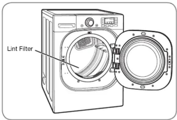
text_image
Lint FilterAlways clean the lint filter after every cycle.
To clean, open the dryer door and pull the lint filter straight up. Then:
1 Roll any lint off the filter with your fingers, or
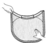
② Vacuum the lint filter, or
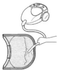
natural_image
Illustration of a handheld device connected to a shield, with a hand holding the shield (no text or symbols present)3 Wash the lint filter in warm, soapy water and allow to dry thoroughly before reinstalling.
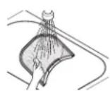
NOTE: NEVER operate the dryer without the lint filter in place.
BEFORE CALLING FOR SERVICE
Your dryer is equipped with an automatic error-monitoring system to detect and diagnose problems at an early stage. If your dryer does not function properly or does not function at all, check the following before you call for service.
| Problem Possible Causes Solutions | ||
| Dryer will not turn on | Power cord is not properly plugged in.House fuse is blown, circuit breaker has tripped, or power outage has occurred. | Make sure that the plug is plugged securely into a grounded outlet matching the dryer's rating plate.Reset circuit breaker or replace fuse. Do not increase fuse capacity. If the problem is a circuit overload, have it corrected by a qualified electrician. |
| Dryer does not heat | House fuse is blown, circuit breaker has tripped, or power outage has occurred.Gas supply or service turned off (gas models only). | Reset circuit breaker or replace fuse. Do not increase fuse capacity. If the problem is a circuit overload, have it corrected by a qualified electrician.Confirm that the house gas shutoff and the dryer gas shutoff are both fully open. |
| Greasy or dirty spots on clothes | Fabric softener used incorrectly.Clean and dirty clothes being dried together.Clean and dirty clothes being dried together. | Confirm and follow the instructions provided with your fabric softener.Make sure to use your dryer to dry only clean items, because dirty items can soil clean clothes placed in the same or subsequent loads.Stains on dried clothes are actually stains that weren't removed during the washing process. Make sure that clothes are being completely cleaned according to the instructions for your washer and detergent. |
| Display shows error code tE1 or tE2 | Thermistor is malfunctioning. | Turn off the dryer and call for service. |
| Lint on clothes | Lint filter not cleaned properly.Laundry not sorted properly.Excess static in clothes.Dryer is overloaded.Tissue, paper, etc., left in pockets. | Make sure the lint filter is cleaned before every load. With some loads that produce high amounts of lint, it may be necessary to clean the filter during the cycle.Some fabrics are lint producers (i.e., a fuzzy white cotton towel) and should be dried separately from clothes that are lint trappers (i.e., a pair of black linen pants).See the Excess static in clothes after drying section below.Divide larger loads into smaller loads for drying.Check pockets thoroughly before washing and drying clothes. |
| Excess static in clothes after drying | Fabric softener not used or used incorrectly.Clothes dried too long (overdried).Drying synthetics, permanent press, or synthetic blends. | Use a fabric softener to reduce static electricity correctly. Do not use fabric softeners or products to eliminate static unless recommended by the manufacturer of the fabric softener or product.Overdrying a load of laundry can cause a buildup of static electricity. Adjust settings and use a shorter drying time, or use SENSOR DRY cycles.These materials can cause static buildup. Try using a fabric softener. |
| Display shows error code PS | Power cord connection is incorrect. | Check the connection of power cord to the terminal block. Refer to 21-24 pages on this manual. |
BEFORE CALLING FOR SERVICE (cont.)
| Problem Possible Causes Solutions | ||
| Drying time is not consistent | Heat settings, load size, or dampness of clothing is not consistent. | The drying time for a load will vary depending on the heat setting, the type of heat used (electric, natural, or LP gas), the size of the load, the type of fabrics, the wetness of the clothes, and the condition of the exhaust ducts and lint filter. |
| Clothes take too long to dry | Load is not properly sorted.Large load of heavy fabrics.Dryer controls are not set properly.Lint filter needs to be cleaned.Exhaust ducts blocked, dirty, or duct run is too long.House fuse is blown, circuit breaker has tripped, or power outage has occurred.Dryer is overloaded.Dryer is underloaded. | Separate heavy items from lightweight items. Larger and heavier items take longer to dry.Heavy fabrics take longer to dry because they tend to retain more moisture. To help reduce and maintain more consistent drying times for large and heavy fabrics, separate these items into smaller loads of a consistent size.Use the appropriate control settings for the type of load you are drying.Make sure the lint filter is cleaned before every load. With some loads that produce high amounts of lint, it may be necessary to clean the filter during the cycle.Confirm that the exhaust ductwork is properly configured and free of debris, lint, and obstructions. Make sure that outside wall dampers can open properly and are not blocked, jammed, or damaged.Reset circuit breaker or replace fuse. Do not increase fuse capacity. If the problem is a circuit overload, have it corrected by a qualified electrician.Divide larger loads into smaller loads for drying.If you are drying a very small load, add a few extra items to ensure proper tumbling action. |
| Clothes are wrinkled | Clothes dried too long (overdried).Clothes left in dryer too long after cycle ends. | Overdrying a load of laundry can lead to wrinkled clothes. Try a shorter drying time, and remove items while they still retain a slight amount of moisture.Remove items from the dryer immediately at the end of the cycle. Use the WRINKLE CARE option to continue tumbling clothes at the end of the cycle, for up to 3 hours. |
| Clothes are shrinking | Garment care instructions are not being followed. | To avoid shrinkage, please carefully follow the fabric care instructions for your garment, because some fabrics will naturally shrink when washed. Other fabrics can be washed but will shrink when dried in a dryer. Use a low or no heat setting and/or the RACK DRY option. |
| The display shows:E3 ERRORAUSTOKEAR, S. B. W. T. M. E. A. C. P. N. O. T. A. G. H. I. J. K. L. K. M. N. A. G. A. H. I. J. K. L. K. M. A. G. A. H. I. J. K. L. K. M. A. G. A. H. I. J. K. L. K. M. A. G. A. H. I. J. K. L. K. M. A. G. A. H. I. J. K. L. K. M. A. G. A. H. I. J. K. L. K. L. M. A. G. A. H. I. J. K. L. K. M. A. G. A. H. I. J. K. L. K. M. A. G. A. H. I. J. K. L. K. M. A. G. A. H. I. J. K. L. K. M. A. G. A. H. I. J. K. L. M. A. G. A. H. I. J. K. L. K. M. A. G. A. H. I. J. K. L. K. M. A. G. A. H. I. J. K. L. K. M. A. G. A. H. I. J. K. L. K. M. A. G. A. H. I. J. M. L. K. M. A. G. A. H. I. J. K. L. K. M. A. G. A. H. I. J. K. L. K. M. A. G. A. H. I. J. K. L. K. M. A. G. A. H. I. J. K. L. K. M. A. G. A. H. I. J. M. L. M. A. G. A. H. I. J. K. L. K. M. A. G. A. H. I. J. K. L. K. M. A. G. A. H. I. J. K. L. K. M. A. G. A. H. I. J. K. L. K. M. A. G. A. H. I. J. K. M. A. G. A. H. I. J. K. L. K. M. A. G. A. H. I. J. K. L. K. M. A. G. A. H. I. J. K. L. K. M. A. G. A. H. I. J. K. L. K. M. A. G. A. H. I. J. K. M. B. C. A. H. I. J. K. L. K. M. A. G. A. H. I. J. K. L. K. M. A. G. A. H. I. J. K. L. K. M. A. G. A. H. I. J. K. L. K. M. A. G. A. H. I. J. K. L. K. M. A. C. A. H. I. J. K. L. K. M. A. G. A. H. I. J. K. L. K. M. A. G. A. H. I. J. K. L. K. M. A. G. A. H. I. J. K. L. K. M. A. G. A. H. I. J. K. L. K. M. B. C. A. H. I. J. K. L. K. M. A. G. A. H. I. J. K. L. K. M. A. G. A. H. I. J. K. L. K. M. A. G. A. H. I. J. K. L. K. M. A. G. A. H. I. J. K. M. B. C. A. F. C. A. H. I. J. K. L. K. M. A. G. A. H. I. J. K. L. K. M. A. G. A. H. I. J. K. L. K. M. A. G. A. H. I. J. K. L. K. M. A. G. A. H. I. J. K. L. K. M. C. A. F. C. A. H. I. J. K. L. K. M. A. G. A. H. I. J. K. L. K. M. A. G. A. H. I. J. K. L. K. M. A. G. A. H. I. J. K. L. K. M. A. G. A. H. I. J. K. M. B. C. B. A. H. I. J. K. L. K. M. A. G. A. H. I. J. K. L. K. M. A. G. A. H. I. J. K. L. K. M. A. G. A. H. I. J. K. L. K. M. A. G. A. H. I. J. K. L. K. M. A. B. C. A. H. I. J. K. L. K. M. A. G. A. H. I. J. K. L. K. M. A. G. A. H. I. J. K. L. K. M. A. G. A. H. I. J. K. L. K. M. A. G. A. H. I. J. K. L. K. N. C. A. F. C. A. H. I. J. K. L. K. M. A. G. A. H. I. J. K. L. K. M. A. G. A. H. I. J. K. L. K. M. A. G. A. H. I. J. K. L. K. M. A. G. A. H. I. J. K. K. L. M. A. G. A. H. I. J. K. L. K. M. A. G. A. H. I. J. K. L. K. M. A. G. A. H. I. J. K. L. K. M. A. G. A. H. I. J. K. L. K. M. A. G. A. H. I. J. L. K. L. K. M. A. G. A. H. I. J. K. L. K. M. A. G. A. H. I. J. K. L. K. M. A. G. A. H. I. J. K. L. K. M. A. G. A. H. I. J. K. L. K. M. A. G. A. H. I. K. L. K. M. A. G. A. H. I. J. K. L. K. M. A. G. A. H. I. J. K. L. K. M. A. G. A. H. I. J. K. L. K. M. A. G. A. H. I. J. K. L. K. M. A. G. A. H. I. L. K. L. K. M. A. G. A. H. I. J. K. L. K. M. A. G. A. H. I. J. K. L. K. M. A. G. A. H. I. J. K. L. K. M. A. G. A. H. I. J. K. L. K. M. A. G. A. H.I. J. K. L. K. M. A. G. A. H. I. J. K. L. K. M. A. G. A. H. I. J. K. L. K. M. A. G. A. H. I. J. K. L. K. M. A. G. A. H. I. J. K. L. K. M. A. G. A. H.10000000000000000000000000000000000000000000000000000000000000000000000000000000000000000000000000000 | ||
| Water drips from nozzle when Steam Cycle starts. | This is normal. | This is steam condensation. The dripping water will stop after a short time. |
BEFORE CALLING FOR SERVICE (cont.)
| Problem Possible | Causes Solutions | |
| Steam doesn't generate but no error code is shown. | Water level error. | Unplug dryer and call for service. |
| Garments still wrinkled after STEAMFRESH^TM . | Too many or too different types of garments in dryer. | Small loads of 1 to 5 items work best.Load fewer garments. Load similar-type garments. |
| There are no creases left on garment after STEAMFRESH^TM . | The function of this cycle is to remove wrinkles from fabric. | Use an iron to make creases. |
| Garments have static after REDUCE STATIC. | This is normal. | Depends on individual moisture level in skin. |
| Garments are too damp or too dry after REDUCE STATIC. | Correct drying options not selected. | Select load weight manually before starting REDUCE STATIC option. |
| Garments are not uniformly damp after EASY IRON. | This is normal. | Depends on the amount or type of garments. |
| Water drips from door during Steam Cycle. | This is normal. | This is steam condensation on door surface. |
| Steam is not visible during Steam Cycle. | This is normal. | Steam vapor is difficult to see when the door is closed. |
| Drum does not turn during Steam Cycle. | This is normal. | The drum is turned off so that the steam vapor remains in the drum. |
| Cannot see steam vapor at the beginning of cycle. | This is normal. | Steam is released at different stages of the cycle for each option. |
| The display shows BULKY LOAD. | MORE TIME button pressed. | Pressing the MORE TIME button several times will set the cycle for a large load such as a comforter. |
| Odors remain in clothing after STEAMFRESH^TM . | STEAMFRESH did not remove odor completely. | Fabrics containing strong odors should be washed in a normal cycle. |
| CHECK FILTER light is on during the drying cycle | Lint filter is almost clogged or full. | Pause the drying cycle and clean the lint filter. |
2 bars are displayed In the LCD screen.  | Ductwork is slightly too long or has too many turns/restrictions.Partial blockage of the ductwork due to lint buildup. | Install a shorter or straighter duct run. See the Installation Instructions.Ductwork should be checked/cleaned soon. Dryer can be used in this condition, but drying times may be longer.If “END OF CYCLE” is displayed after the end of cycle, it will be off in 4 minutes. If POWER button is pressed or the door is opened, power will be off immediately. |
4 bars are displayed In the LCD screen. 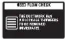 | Ductwork is too long or has too many turns/restrictions.Significant blockage of the ductwork due to lint buildup or debris. | Install a shorter or straighter duct run. See the Installation Instructions.Ductwork should be checked/cleaned soon. Dryer can be used in this condition, but drying times may be longer.If “NEED FLOW CHECK” is displayed after the end of cycle, it will be off in 2 hours. If POWER button is pressed or the door is opened, power will be off immediately. |
USING SMARTDIAGNOSISTM
- Only use this feature when instructed to do so by the call center. The transmission sounds similar to a fax machine, and so has no meaning except to the call center.
- SmartDiagnosis™ cannot be activated if the dryer does not power up. If this happens, then troubleshooting must be done without SmartDiagnosis™.
If you experience problems with your dryer, call 1-800-243-0000 (1-888-542-2623 in Canada). Follow the call center agent's instructions, and do the following steps when requested:
1 Press the POWER button to turn on the dryer.
Do not press any other buttons or turn the cycle selector knob.
② When instructed to do so by the call center, place the mouthpiece of your phone very close to the POWER button.

text_image
SMART DIAGNOSIS™3 Press and hold the TEMP. CONTROL button for three seconds, while holding the phone mouthpiece to the icon or POWER button.
4 Keep the phone in place until the tone transmission has finished. This takes about 15 seconds, and the display will count down the time.
- For best results, do not move the phone while the tones are being transmitted.
- If the call center agent is not able to get an accurate recording of the data, you may be asked to try again.
- Pressing the POWER button during the transmission will shut off the SmartDiagnosis™.
5 Once the countdown is over and the tones have stopped, resume your conversation with the call center agent, who will then be able to assist you using the information transmitted for analysis at the call center.
OPTIONAL ACCESSORIES
For these and other LG products, contact your local LG dealer, or visit our Web site at www.lg.com
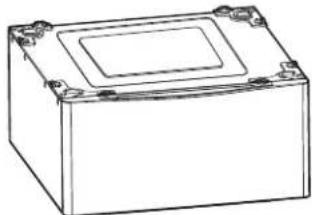
natural_image
Line drawing of a rectangular electronic component with mounting holes and a central square top (no text or symbols)Pedestal
Give your LG washer and dryer a boost with matching 14-inch high pedestals. They feature a storage drawer for added convenience.
14" Pedestal Color
WDP4C Chardonnay steel
WDP4V Graphite steel
WDP4W White
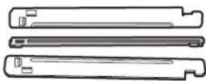
Stacking Kit
If space is at a premium, use this kit to securely stack your LG front-load washer and dryer.
Stacking Kit Color
CSTK1 Chardonnay
SSTK1 Titanium
WSTK1 White
PEDESTAL INSTALLATION
The pedestal accessory includes:
- Drawer divider (1) • Wrench (1)
- Screws (18) †
- Retainers (4) ††

text_image
† Dryer installation only uses 8 screws †† For dryer onlyTools Needed for Installation:
• Phillips-head screwdriver
- Wrench (supplied)
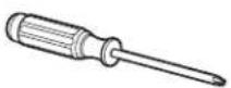
To ensure safe and secure installation, please thoroughly follow the instructions below.
WARNING
- Incorrect installation can cause serious accidents.
- The appliances are heavy. Two or more people are required when installing the pedestal. There is a risk of serious back injury or other injuries.
- Do not allow children to play in or on the drawer. There is a risk of suffocation or injury.
- Do not step on the handle. There is a risk of serious injury.
- If appliances are already installed, disconnect them from all power, water, or gas lines and from draining or venting connections. Failure to do so can result in electrical shock, fire, explosion, or death.
- When installing, gloves must be put on.
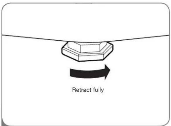
text_image
Retract fully1 Make sure the leveling feet of the dryer are fully retracted.
NOTE: The appliance and pedestal assembly must be placed on a solid, sturdy, level floor for proper operation.
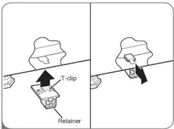
text_image
T-clip Retainer2 Insert the T-clip of the 4 retainers into the dryer base as shown. Press up on the back of the clip and pull outward to lock into place.
OPTIONAL ACCESSORIES
PEDESTAL INSTALLATION (cont.)
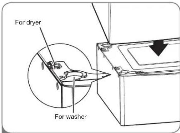
text_image
For dryer For washer3 Place the dryer on the pedestal. Make sure the front and back feet are in the correct positions. The dryer feet will fit into the innermost positions as shown.
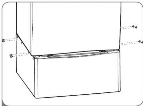
natural_image
Technical line drawing of a 3D rectangular box with internal components and mounting holes (no text or symbols)4 Make sure the screws on the pedestal align with the holes in the retainers, then install 4 screws on each side to securely attach the appliance to the pedestal.
NOTE: If the screws are not installed properly, noise and vibration may result.
Move the appliance to the desired location.
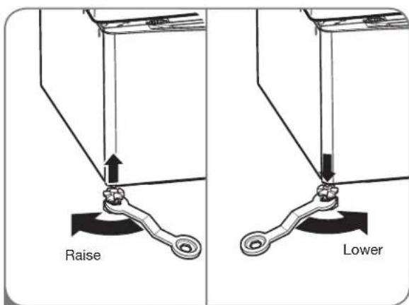
text_image
Raise Lower5 Loosen the locknuts on all 4 leveling feet of the pedestal until you can turn them with the wrench. Turn clockwise to raise or counterclockwise to lower until the pedestal is level and all 4 feet are solidly against the floor.
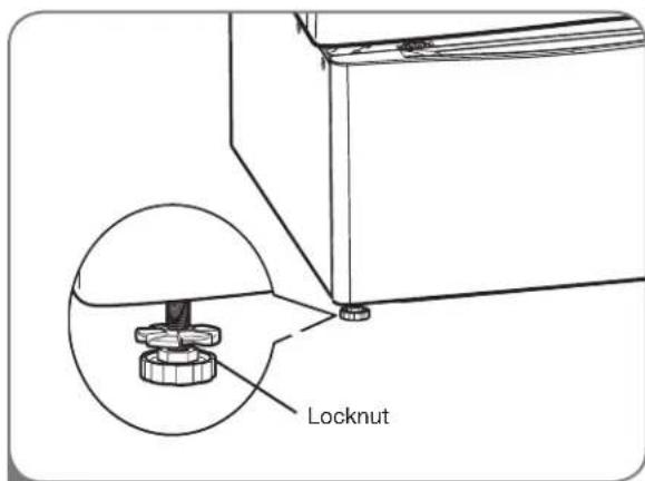
text_image
Locknut6 Securely tighten all locknuts by hand.
NOTE: Noise and vibration may result if locknuts are not tightened.
Be sure to connect the appliances to all water, power, or gas lines and draining or venting connections before operation.
If there is excessive vibration during the first operation after installation, slightly adjust the leveling feet.
STACKING KIT INSTALLATION
This stacking kit includes:
- Two (2) side rails
- One (1) front rail
- Four (4) screws
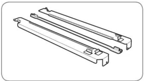
natural_image
Technical line drawing of three parallel metal bracket components (no text or symbols)Tools Needed for Installation:
• Phillips-head screwdriver
To ensure safe and secure installation, please observe the following instructions.
WARNING
- Incorrect installation can cause serious accidents.
- The weight of the dryer and the height of installation make this stacking procedure too risky for one person. Two or more people are required when installing the stacking kit. There is a risk of serious back injury or other injuries.
- Do not use the stacking kit with a gas dryer in potentially unstable conditions such as a mobile home. Failure to follow this warning can result in serious injury.
- Place the washer on a solid, stable, level floor capable of supporting the weight of both appliances. Failure to follow this warning can result in serious injury.
- Do NOT stack the washer on top of the dryer. Failure to follow this warning can result in serious injury.
- If appliances are already installed, disconnect them from all power, water, or gas lines and from draining or venting connections. Failure to do so can result in electrical shock, fire, explosion, or death.
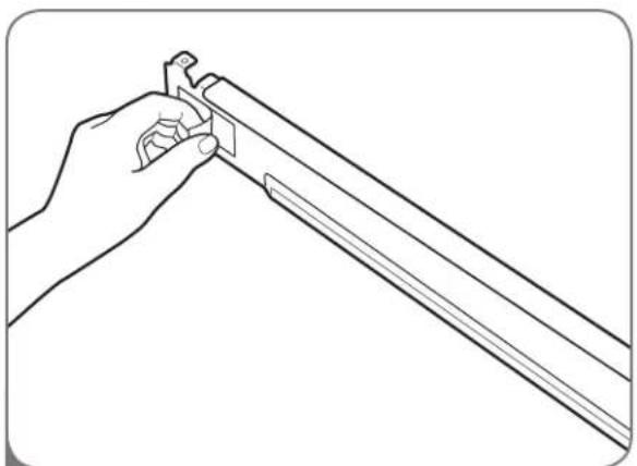
natural_image
Line drawing of a hand holding a tool, no text or symbols present1 Make sure the surface of the washer is clean and dry. Remove paper backing from the tape on one of the stacking kit side brackets.
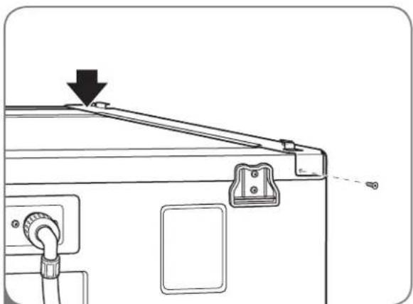
natural_image
Technical line drawing of a mechanical device with a downward arrow indicating a component (no text or symbols present)2 Fit the side bracket to the side of the washer top as shown in the above illustration. Firmly press the adhesive area of the bracket to the washer surface. Secure the side bracket to the washer with a screw on the back side of the bracket. Repeat steps 1 and 2 to attach the other side bracket.
STACKING KIT INSTALLATION (cont.)
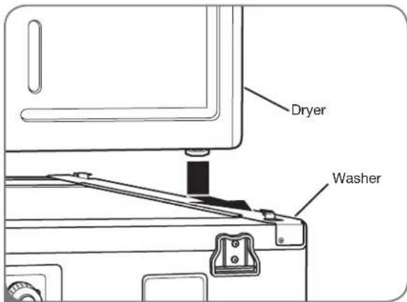
text_image
Dryer Washer3
Place the dryer on top of the washer by fitting the dryer feet into the side brackets as illustrated. Avoid finger injuries; do not allow fingers to be pinched between the washer and dryer. Slowly slide the dryer toward the back of the washer until the side bracket stoppers catch the dryer feet.
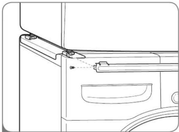
natural_image
Technical line drawing of a mechanical component with no visible text or symbols4
Insert the front rail between the bottom of the dryer and the top of the washer. Push the front rail toward the back of the washer until it comes in contact with the side rail stoppers. Install the two remaining screws to secure the front rail to the side rails.
SPECIFICATIONS
KEY DIMENSIONS AND SPECIFICATIONS
The appearance and specifications listed in this guide may vary due to constant product improvements.
| Steam DryerTM Models LSDE388VS LSDG389VS | |
| Description Steam Dryer | |
| Electrical Requirements* | Please refer to the rating label regarding detailed information. |
| Gas Requirements* NG: 4-10.5 inches WCLP: 8-13 inches WC (Gas Models only) | |
| Dimensions 27" (W) X 30" (D) X 38 ^11/16 " (H), 51" (D with door open)68.6 cm (W) X 76.1 cm (D) X 98.3 cm (H), 129.7 cm (D with door open) | |
| Net Weight 147.7 lb (67 kg) | |
| Drying Capacity- Normal Cycle IEC 7.4 cu.ft. (22.5 lb/10.2 kg)- Steam Cycle IEC 7.4 cu.ft. (8 lb/3.6 kg) | |
*Refer to the rating plate on your dryer.
LG ELECTRONICS, INC. LG DRYER LIMITED WARRANTY - USA

Your LG Dryer will be will repaired or replaced, at LG's option, if it proves to be defective in material or workmanship under normal use, during the warranty period ("Warranty Period") set forth below, effective from the date ("Date of Purchase") of original consumer purchase of the product. This warranty is good only to the original purchaser of the product and effective only when used in the United States, including Alaska, Hawaii, and U.S. Territories.
WARRANTY PERIOD:
LABOR: Two Years from the Date of Purchase.
PARTS: Two Years from the Date of Purchase.
Replacement Units and Repair Parts may be new or remanufactured.
Replacement Units and Repair Parts are warranted for the remaining portion of the original unit's warranty period.
Dryer drum 10 years limited warranty
Parts only. Customer will be responsible for any labor or in-home service to replace defective parts.
HOW SERVICE IS HANDLED:
In-Home Service:
Please retain dealer's dated bill of sale or delivery ticket as evidence of the Date of Purchase for proof of warranty, and submit a copy of the bill of sale to the service person at the time warranty service is provided.
Please call 1-800-243-0000 and choose the appropriate option to locate your nearest LG Authorized Service Center.
Or visit our Web site at: http://www.lgservice.com.
THIS WARRANTY IS IN LIEU OF ANY OTHER WARRANTY, EXPRESS OR IMPLIED, INCLUDING WITHOUT LIMITATION, ANY WARRANTY OF MERCHANTABILITY OR FITNESS FOR A PARTICULAR PURPOSE. TO THE EXTENT ANY IMPLIED WARRANTY IS REQUIRED BY LAW, IT IS LIMITED IN DURATION TO THE EXPRESS WARRANTY PERIOD ABOVE. NEITHER THE MANUFACTURER NOR ITS U.S. DISTRIBUTOR SHALL BE LIABLE FOR ANY INCIDENTAL, CONSEQUENTIAL, INDIRECT, SPECIAL, OR PUNITIVE DAMAGES OF ANY NATURE, INCLUDING WITHOUT LIMITATION, LOST REVENUES OR PROFITS, OR ANY OTHER DAMAGE WHETHER BASED IN CONTRACT, TORT, OR OTHERWISE. Some states do not allow the exclusion or limitation of incidental or consequential damages or limitations on how long an implied warranty lasts, so the above exclusion or limitation may not apply to you. This warranty gives you specific legal rights and you may also have other rights that vary from state to state.
THIS LIMITED WARRANTY DOES NOT APPLY TO:
- Service trips to your home to deliver, pick up, and/or install the product, instruct, or replace house fuses or correct wiring, or correction of unauthorized repairs.
- Damages or operating problems that result from misuse, abuse, operation outside environmental specifications or contrary to the requirements of precautions in the Operating Guide, accident, vermin, fire, flood, improper installation, acts of God, unauthorized modification or alteration, incorrect electrical current or voltage, or commercial use, or use for other than intended purpose.
The cost of repair or replacement under these excluded circumstances shall be borne by the consumer.
CUSTOMER INFORMATION CENTER NUMBERS
To obtain Customer Assistance, Product Information, or Dealer or Authorized Service Center location:
Call 1-800-243-0000 (24 hours a day, 365 days per year), and select the appropriate option from the menu. Or visit our Web site at: http://www.lgservice.com.
TO CONTACT LG ELECTRONICS BY MAIL:
LG Customer Information Center
P. O. Box 240007
201 James Record Road
Huntsville, Alabama 35824
ATTN: CIC
Product Registration Information
Model:
Serial Number:
Date of Purchase:
The model and serial number can be located on the rating plate inside the front door.
LG ELECTRONICS CANADA, INC. LG DRYER LIMITED WARRANTY - Canada
WARRANTY: Should your LG Dryer (“Product”) fail due to a defect in material or workmanship under normal home use during the warranty period set forth below, LG Canada will at its option repair or replace the Product upon receipt of proof of original retail purchase. This warranty is valid only to the original retail purchaser of the product and applies only to a Product distributed in Canada by LG Canada or an authorized Canadian distributor thereof. The warranty only applies to Products located and used within Canada.
| WARRANTY PERIOD: (Note: If the original date of purchase can not be verified, the warranty will begin sixty (60) days from the date of manufacture). |
| Dryer |
| One (1) year from the date of original retail purchase |
| Parts and Labor (internal/functional parts only) |
| Dryer drum 10 years limited warranty |
| Parts only. Customer will be responsible for any labor or in-home service to replace defective parts. |
- Replacement products and parts are warranted for the remaining portion of the original warranty period or ninety (90) days, whichever is greater.
- Replacement products and parts may be new or remanufactured.
• LG Authorized Service Center warranties their repair work for thirty (30) days.
LG CANADA'S SOLE LIABILITY IS LIMITED TO THE WARRANTY SET OUT ABOVE. EXCEPT AS EXPRESSLY PROVIDED ABOVE, LG CANADA MAKES NO AND HEREBY DISCLAIMS ALL OTHER WARRANTIES AND CONDITIONS RESPECTING THE PRODUCT, WHETHER EXPRESS OR IMPLIED, INCLUDING, BUT NOT LIMITED TO, ANY IMPLIED WARRANTY OR CONDITION OF MERCHANTABILITY OR FITNESS FOR A PARTICULAR PURPOSE, AND NO REPRESENTATIONS SHALL BE BINDING ON LG CANADA. LG CANADA DOES NOT AUTHORIZE ANY PERSON TO CREATE OR ASSUME FOR IT ANY OTHER WARRANTY OBLIGATION OR LIABILITY IN CONNECTION WITH THE PRODUCT. TO THE EXTENT THAT ANY WARRANTY OR CONDITION IS IMPLIED BY LAW, IT IS LIMITED TO THE EXPRESS WARRANTY PERIOD ABOVE. LG CANADA, THE MANUFACTURER OR DISTRIBUTOR SHALL NOT BE LIABLE FOR ANY INCIDENTAL, CONSEQUENTIAL, SPECIAL, DIRECT OR INDIRECT DAMAGES, LOSS OF GOODWILL, LOST PROFITS, PUNITIVE OR EXEMPLARY DAMAGES OR ANY OTHER DAMAGE, WHETHER ARISING DIRECTLY OR INDIRECTLY FROM ANY CONTRACTUAL BREACH, FUNDAMENTAL OR OTHERWISE, OR FROM ANY ACTS OR OMISSIONS, TORT, OR OTHERWISE.
This warranty gives you specific legal rights. You may have other rights which may vary from province to province depending on applicable provincial laws. Any term of this warranty that negates or varies any implied condition or warranty under provincial law is severable where it conflicts with provincial law without affecting the remainder of this warranty's terms.
THIS LIMITED WARRANTY DOES NOT COVER:
- Service trips to deliver, pick up, or install the product; instructing a customer on operation of the product; repair or replacement of fuses or correction of wiring, or correction of unauthorized repairs/installation.
- Failure of the product to perform during power failures and interruptions or inadequate electrical service.
- Damage caused by leaky or broken water pipes, frozen water pipes, restricted drain lines, inadequate or interrupted water supply or inadequate supply of air.
- Damage resulting from operating the Product in a corrosive atmosphere or contrary to the instructions outlined in the Product owner's manual.
- Damage to the Product caused by accidents, pests and vermin, lightning, wind, fire, floods, or acts of God.
- Damage resulting from the misuse, abuse, improper installation, repair, or maintenance of the Product. Improper repair includes use of parts not approved or specified by LG Canada.
- Damage or product failure caused by unauthorized modification or alteration, or use for other than its intended purpose, or resulting from any water leakage due to improper installation.
- Damage or Product failure caused by incorrect electrical current, voltage, commercial or industrial use, or use of accessories, components, or cleaning products that are not approved by LG Canada.
- Damage caused by transportation and handling, including scratches, dents, chips, and/or other damage to the finish of your product, unless such damage results from defects in materials or workmanship and is reported within one (1) week of delivery.
- Damage or missing items to any display, open box, discounted, or refurbished Product.
- Products with original serial numbers that have been removed, altered, or cannot be readily determined. Model and Serial numbers, along with original retail sales receipt, are required for warranty validation.
- Increases in utility costs and additional utility expenses. Replacement of light bulbs, filters, or any consumable parts. Repairs when your Product is used in other than normal and usual household use (including, without limitation, commercial use, in offices or recreational facilities) or contrary to the instructions outlined in the Product owner's manual.
- Costs associated with removal of the Product from your home for repairs.
- The removal and reinstallation of the Product if it is installed in an inaccessible location or is not installed in accordance with published installation instructions, including the Product owner's and installation manuals.
- Accessories to the Product such as door bins, drawers, handles, shelves, etc.. Also excluded are parts besides those that were originally included with the Product.
All costs associated with the above excluded circumstances shall be borne by the consumer.
For complete warranty details and customer assistance, please call or visit our website:
Call 1-888-542-2623 (24 hours a day, 365 days a year) and select the appropriate option from the menu, or visit our website at http://www.lg.ca
Write your warranty information below:
Product Registration Information:
Model:
Serial Number:
Date of Purchase:
NOTES
MANUAL DE PROPIETARIO
SECADORA
natural_image
Silhouette of a hanger holding a garment and a spray bottle, both without any text or symbols.LEA TODAS LA INSTRUCCIONES ANTES DE USAR
ADVERTENCIA
text_image
Diagram of a washing machine with labeled parts including front panel, door, and side panelsH DIAGNÓSTICOINTELIGENTE™
text_image
Diagram of a front-loading washing machine with labeled parts A and B, showing internal components and door opening.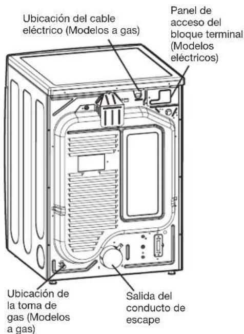
natural_image
Line drawing of a rectangular electronic component with mounting holes and a central square top (no text or symbols)natural_image
Diagram showing two mechanical components with wrenches and a central fastener, no text or symbols presentnatural_image
Technical line drawing of a washing machine interior with mounting holes and control panel (no text or symbols)natural_image
Technical line drawing of a mechanical component with circular and rectangular parts, no visible text or symbolsnatural_image
Illustration of a hand holding a plug inserted into an electrical outlet (no text or symbols)natural_image
Line drawing of a vertical industrial machine with ductwork and control panel (no text or symbols)natural_image
Two schematic diagrams of industrial equipment with no visible text, numbers, or symbols.text_image
Diagram showing a device with a 'X' symbol crossed out, alongside three circular insets illustrating mechanical components.natural_image
Diagram of a mechanical device with a cross mark and a magnified inset showing internal components (no text or symbols)CARACTERÍSTICAS DEL PANEL DE CONTROL
natural_image
Line drawing of a washing machine with internal components and ventilation slots (no text or symbols)natural_image
Line drawing of a washing machine with open door and side panel (no text or symbols)natural_image
Line drawing of a printer with an arrow indicating upward motion (no text or symbols)natural_image
Diagram of a device with a handle and arrow indicating direction (no text or symbols)natural_image
Illustration of a hand holding a handheld device above a curved panel (no text or symbols visible)natural_image
Line drawing of a rectangular electronic component with mounting holes and a central square lid (no text or symbols)Pedestal
natural_image
Technical line drawing of a 3D rectangular box with internal structure and dimension lines (no text or symbols)text_image
Raise Bajarnatural_image
Technical line drawing of three parallel metal bracket components (no text or symbols)natural_image
Line drawing of a hand holding a tool, no text or symbols presentnatural_image
Technical line drawing of a mechanical device with no visible text or symbolsnatural_image
Technical line drawing of a door handle assembly with mounting bracket and door (no text or symbols)4
201 James Record Road
Huntsville, Alabama 35824
ATTN: CIC
text_image
Diagram of a washing machine with labeled parts including front panel, door, and side panelH SMARTDIAGNOSIS ^MC
CONDITIONS REQUISES POUR L'EMPLACEMENT D'INSTALLATION
natural_image
Line drawing of a rectangular electronic component with mounting holes and a central screen (no text or symbols)natural_image
Diagram showing two mechanical setups with arrows indicating force or movement, no text or symbols presentnatural_image
Technical line drawing of a washing machine interior with mounting brackets and control panel (no text or symbols)natural_image
Technical line drawing showing mechanical assembly with no visible text or symbolsnatural_image
Illustration of a hand inserting a plug into an electrical outlet (no text or symbols)natural_image
Two schematic diagrams of industrial equipment with no visible text, numbers, or symbols.text_image
Diagram showing a device with a black X mark and two inset cross-sections illustrating internal structure or components.natural_image
Cross-sectional diagram of a mechanical device showing internal components and a central component (no text or symbols)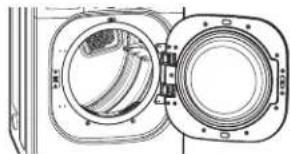
natural_image
Cross-sectional diagram of a mechanical component with two circular housing and internal components (no text or symbols)
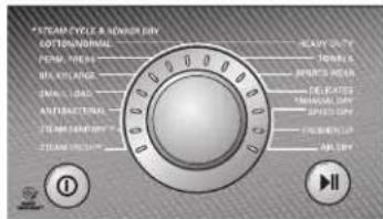
text_image
STEAM CYCLE R. SENSOR DAY COTTON/DRAWN PEWM MEAS MIL KONANGE SPIN' LAGS ANUFACTURING STREAM SANTINY STREAM SANTINY BEAUTY OUT PENNS SPRING MEAS DELICATED TRAVELIC/day SPRING/day LPG/EBIT/LLP MINI/day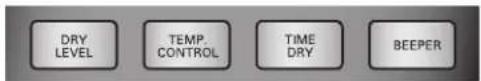
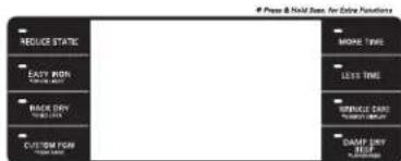
text_image
Press & Hold Base for Extra Patterns REDUCE STATE EASY RIN CORNATE BACK DRY LEFT DRY CUSTOMER FOR SHORT DRY WRITE TIME MORE TIME LESS TIME SPINNICE DRY SHORT TIME DRAFT DRY LEFT DRY

1 NETTOYER LE FILTRE A PELUCHES
natural_image
Line drawing of a washing machine interior showing internal components and airflow direction (no text or symbols)natural_image
Line drawing of an open washing machine with internal compartments and ventilation slots (no text or symbols)FONCTIONS SPÉCIALES
PROGRAMME SPÉCIAL (CUSTOM PROGRAM)

natural_image
Line drawing of a printer with an arrow indicating the process (no text or symbols present)natural_image
Line drawing of a mechanical device with an arrow indicating direction (no text or symbols)IMPORTANTES REMARQUES SUR LES CYCLES VAPEUR :
natural_image
Three technical illustrations showing a mesh device, a vacuum cleaner, and a shield-like object with a tool (no text or symbols)text_image
SMART DIAGNOSIST™ Inatural_image
Line drawing of a rectangular electronic device with mounting holes and a central screen (no text or symbols)Piédestal
natural_image
Technical line drawing of a 3D rectangular frame with internal supports and dimension lines (no text or symbols)natural_image
Technical line drawing of three parallel metal bracket components (no text or symbols)natural_image
Line drawing of a hand holding a tool, no text or symbols presentnatural_image
Technical line drawing of a mechanical component with a downward arrow indicating a feature (no text or symbols present)natural_image
Technical line drawing of a mechanical component with mounting brackets and a handle (no text or symbols)4
Register your product Online!
www.lg.com