BMV712 Smart - Electrical measuring device VICTRON ENERGY - Free user manual and instructions
Find the device manual for free BMV712 Smart VICTRON ENERGY in PDF.
| Product Type | Battery Monitor with Built-in Bluetooth |
| Brand | Victron Energy |
| Model | BMV-712 Smart |
| Dimensions (front face) | 69 x 69 mm |
| Body diameter | 52 mm |
| Total depth | 31 mm |
| Net weight (BMV) | 70 g |
| Net weight (shunt) | 315 g |
| Supply voltage | 6.5 to 70 VDC |
| Power consumption (12 V) | 1 mA (backlight and alarm off) |
| Fuse on positive cable | 1 A, 20 x 5 mm |
| Operating temperature range | -20 to +50 °C |
| Storage temperature | -40 to +60 °C |
| Main functions | State of charge monitoring (%), voltage, current, power, ampere-hours consumed, remaining autonomy, battery temperature, midpoint voltage, auxiliary battery, data history, configurable alarms, bistable relay, Peukert compensation, charge efficiency |
| Connectivity | Built-in Smart Bluetooth, VE.Direct port for USB cable or Color Control GX |
| Auxiliary input (configurable) | Starter battery, midpoint voltage or temperature probe |
| Shunt supplied | 500 A / 50 mV |
| Display | LCD with backlight, adjustable intensity |
| Maintenance and cleaning | No specific maintenance; store in a dry place; clean with a soft, dry cloth |
| Safety | Observe precautions for lead-acid batteries (explosive gases); wear safety goggles and gloves; avoid short circuits; do not expose to water |
| Spare parts and repairability | Replaceable shunt (reference supplied); optional temperature probe (ASS000100000); standard 1 A fuse; no user-serviceable parts inside |
| Warranty | Consult the Victron Energy warranty document |
Frequently Asked Questions - BMV712 Smart VICTRON ENERGY
User questions about BMV712 Smart VICTRON ENERGY
0 question about this device. Answer the ones you know or ask your own.
Ask a new question about this device
Download the instructions for your Electrical measuring device in PDF format for free! Find your manual BMV712 Smart - VICTRON ENERGY and take your electronic device back in hand. On this page are published all the documents necessary for the use of your device. BMV712 Smart by VICTRON ENERGY.
USER MANUAL BMV712 Smart VICTRON ENERGY
1.1 Battery capacity
1.2 Auxiliary input (BMV-702 and BMV-712 Smart only)
1.3 Important combined button functions
2 NORMAL OPERATING MODE
2.1 Read-out overview
2.2 Synchronising the BMV
2.3 Common problems
3 FEATURES AND FUNCTIONALITY
3.1 Features of the three BMV models
3.2 Why should I monitor my battery?
3.3 How does the BMV work?
3.3.1 About battery capacity and the rate of discharge
3.3.2 About charge efficiency (CEF)
3.4 Several battery state of charge display options
3.5 History data
3.6 Use of alternative shunts
3.7 Automatic detection of nominal system voltage
3.8 Alarm, buzzer and relay
3.9 Interface options
3.9.1 PC Software
3.9.2 Large display and remote monitoring
3.9.3 Custom integration (programming required)
3.10 Additional functionality of the BMV-702 and BMV-712 Smart
3.10.1 Auxiliary battery monitoring
3.10.2 Battery temperature monitoring
3.10.3 Midpoint voltage monitoring
3.11 Additional functionality of the BMV-712 Smart
3.11.1 Automatic cycling through status-items
3.11.2 Turning Bluetooth On/Off
4 FULL SETUP DETAILS
4.1 Using the menus
4.2 Function overview
4.2.1 Battery settings
4.2.2 Relay settings
4.2.3 Alarm-Buzzer settings
4.2.4 Display settings
4.2.5 Miscellaneous
4.3 History data
5 MORE ABOUT PEUKERT'S FORMULA AND MIDPOINT MONITORING
6 LITHIUM IRON PHOSPHATE BATTERIES (LiFePO4)
7 DISPLAY
8 TECHNICAL DATA
Safety Precautions

- Working in the vicinity of a lead acid battery is dangerous. Batteries can generate explosive gases during operation. Never smoke or allow a spark or flame in the vicinity of a battery. Provide sufficient ventilation around the battery.
- Wear eye and clothing protection. Avoid touching eyes while working near batteries. Wash your hands when done.
- If battery acid contacts skin or clothing, wash them immediately with soap and water. If acid enters an eye, immediately flood the eye with running cold water for at least 15 minutes and get medical attention immediately.
- Be careful when using metal tools in the vicinity of batteries. Dropping a metal tool onto a battery might cause a short circuit and possibly an explosion.
- Remove personal metal items such as rings, bracelets, necklaces, and watches when working with a battery. A battery can produce a short circuit current high enough to melt objects such as rings, causing severe burns.
Transport and storage
• Store the product in a dry environment.
• Storage temperature: -40^ to +60^
1 QUICK START GUIDE
This quick start guide assumes that the BMV is being installed for the first time, or that factory settings have been restored.
Please see the appendix at the end of this manual for wiring suggestions.
The factory settings are suitable for the average lead acid battery: flooded, GEL or AGM.
The BMV will automatically detect the nominal voltage of the battery system immediately after completion of the setup wizard (for details and limitations of automatic nominal voltage detection, see section 3.8).
Therefore the only settings which need to be made are the battery capacity (BMV-700 and BMV-700H), and the functionality of the auxiliary input (BMV-702 and BMV-712).
Please install the BMV in accordance with the quick installation guide. After inserting the fuse in the positive supply cable to the main battery, the BMV will automatically start the setup wizard.
The setup wizard below must be completed before other settings can be made. Alternatively, use the VictronConnect app and a smart phone.
Remarks:
a) In case of solar applications or Li-ion batteries several settings may have to be changed. Please refer to section 2.3 resp. section 6. The setup wizard below must be completed before other settings can be made.
b) When using a shunt other than the one supplied with the BMV, please refer to section 3.6. The setup wizard below must be completed before other settings can be made.
c) Bluetooth
Use a Bluetooth Smart enabled device (smart phone or tablet) for easy and fast initial setup, for changing settings and for real time monitoring.
BMV-700 or -702: VE.Direct Bluetooth Smart dongle needed.
BMV-712 Smart: Bluetooth enabled, no dongle needed. Ultra low current draw.
Bluetooth:
VE.Direct Bluetooth Smart dongle: see the manual on our website https://www.victronenergy.com/live/ve.direct:ve.direct_to_bluetooth_smart_dongle
BMV-712 Smart:
Download the VictronConnect app (see Downloads on our website) https://www.victronenergy.com/live/victronconnect:start
Pairing procedure: the default PIN code is 000000
After connecting, the PIN code can be changed by pressing the (i) button in the top right of the app.
If the dongle PIN code is lost, reset it to 000000 by pressing and holding the clear PIN button until the solid blue colored Bluetooth light flashes off and on momentarily.
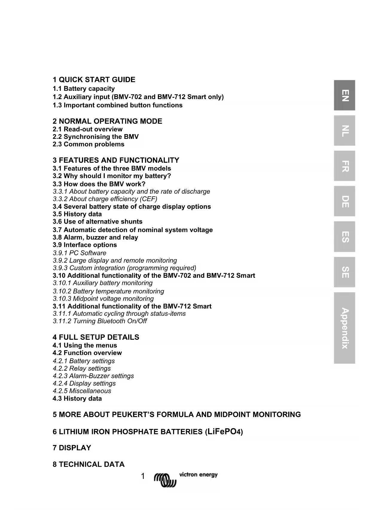
text_image
BMV-702 STATUS HISTORY State of charge 85% Output Voltage 25.46V Current -7.5A Consumed Ah 25Ah Time remaining 5h 0m Input Starter battery 12.80V ResetSetup wizard (alternatively, use the VictronConnect app and smart phone):
1.1 Battery capacity (preferably use the 20 hour capacity rating ( C_20 ))
a) After inserting the fuse the display will show the scrolling text
01 battery capacity
If this text is not shown, press SETUP and SELECT simultaneously during 3 seconds to restore factory settings or go to section 4 for full setup details (setting 64, Lock setup, must be OFF to restore factory settings, see section 4.2.5).
b) Press any button to stop scrolling and the factory default value 0200 Ah will appear in edit mode: the first digit will blink.
Enter the desired value with the + and - buttons.
c) Press SELECT to set the next digit in the same manner.
Repeat this procedure until the required battery capacity is displayed.
The capacity is automatically stored in non-volatile memory when the last digit has been set by pressing SELECT. This is indicated with a short beep.
If a correction has to be made, press SELECT again and repeat the procedure.
d) BMV-700 and 700H: press SETUP or + or – to end the setup wizard and switch to normal operating mode.
BMV-702: press SETUP or + or – to proceed to auxiliary input setting.
1.2 Auxiliary input (BMV-702 and -712 only)
a) The display will show AUHI LI ARY InPUE scrolling.
b) Press SELECT to stop scrolling and the LCD will show: SETA
Use the + or - key to select the required function of the auxiliary input:
S_tR_t for monitoring the starter battery voltage.
if d for monitoring the midpoint voltage of a battery bank.
EEP for using the optional temperature sensor
Press SELECT to confirm. Confirmation is indicated with a short beep.
c) Press SETUP or + or – to end the setup wizard and switch to normal operating mode.
The BMV is now ready for use.
When powered up for the first time, the BMV will by default display 100% state of charge. See section 4.2.1, setting 70 to change this this behaviour.
When in normal mode the backlight of the BMV switches off after no key has been pressed for 60 seconds. Press any key to restore backlight.
The cable with integrated temperature sensor has to be purchased separately (part no: ASS000100000). This temperature sensor is not interchangeable with other Victron temperature sensors, as used with Multis/Quattros or battery chargers.
1.3 Important combined button functions
(see also section 4.1: using the menus)
a) Restore factory settings
Press and hold SETUP and SELECT simultaneously for 3 seconds
b) Manual synchronisation
Press and hold the up and down buttons simultaneously for 3 seconds
c) Silence audible alarm
An alarm is acknowledged when any button is pressed. However, the alarm icon is displayed as long as the alarm condition remains.
1.4 Realtime data displayed on a smartphone
With the VE.Direct Bluetooth Smart dongle realtime data and alarms can be displayed on Apple and Android smartphones, tablets and other devices.
Note:
A VE.Direct Bluetooth Smart dongle is not required for BMV-712, since it has Bluetooth built-in.
2 NORMAL OPERATING MODE
2.1 Readout overview
In normal operating mode the BMV displays an overview of important parameters.
The + and – selection buttons give access to various readouts:
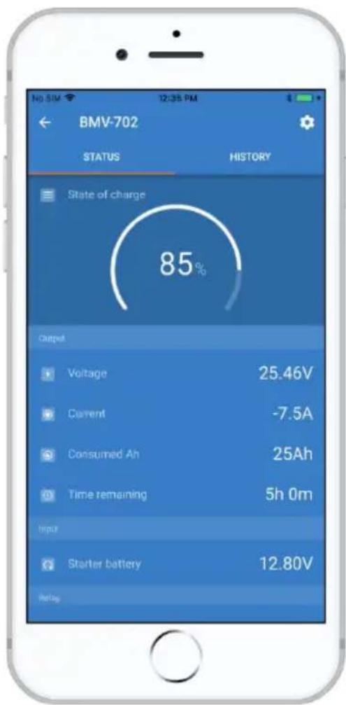
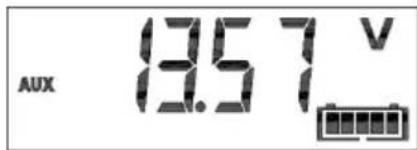
Battery voltage
text_image
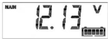
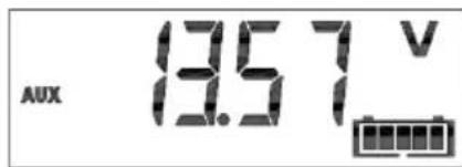
MAIN 12.13 VAuxiliary battery voltage
text_image
AUX 13.57 V BBMV-702 and -712 only, when the auxiliary input is set to START.
Current
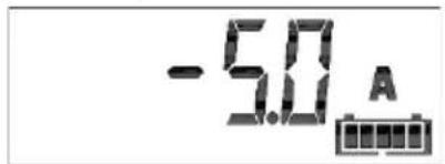
text_image
-5.0 AThe actual current flowing out of the battery (negative sign) or into the battery (no sign).
Power
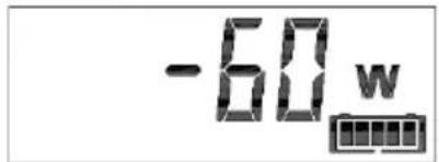
text_image
-60 wThe power drawn from the battery (negative sign) or flowing into the battery (no sign).
Consumed Amp-hours
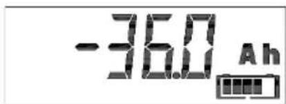
text_image
-36.0 AhThe amount of Ah consumed from the battery
Example:
If a current of 12A is drawn from a fully charged battery for a period of 3 hours, this readout will show -36.0Ah.
$$ (- 1 2 \times 3 = - 3 6) $$
Note:
Three dashes ‘---’ will be shown when the BMV is started in unsynchronised state. See section 4.2.1, setting number 70.
State of charge
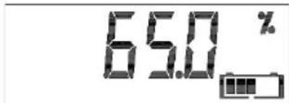
text_image
65.0 %A fully charged battery will be indicated by a value of 100.0%. A fully discharged battery will be indicated by a value of 0.0%.
Note:
Three dashes ‘---’ will be shown when the BMV is started in unsynchronised state. See section 4.2.1, setting number 70.
Time-to-go
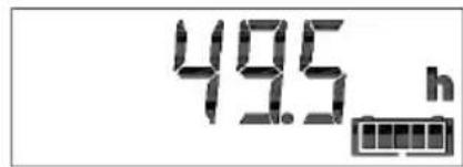
text_image
49.5 hAn estimation of how long the battery can support the present load until it needs recharging.
The time-to-go displayed is the time to reach the discharge floor. See 4.2.2, setting number 16.
Note:
Three dashes ‘---’ will be shown when the BMV is started in unsynchronised state. See section 4.2.1, setting number 70.
Battery temperature
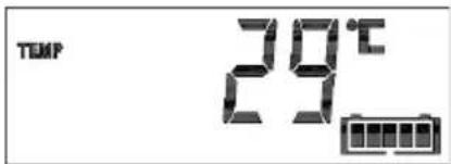
text_image
TEMP 29°CBMV-702 and -712 only, when the auxiliary input is set to TEMP.
The value can be displayed in degrees Celsius or degrees Fahrenheit. See section 4.2.5.
Battery bank top section voltage
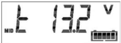
text_image
MID 上 13.2 VBMV-702 and -712 only, when the auxiliary input set to MID.
Compare with the bottom section voltage to check battery balancing. For more about battery midpoint monitoring, see section 5.2.
Battery bank bottom section voltage
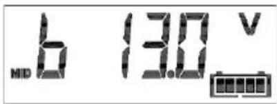
text_image
b 13.0 V NIDBMV-702 and -712 only, when the auxiliary input is set to MID.
Compare with the top section voltage to check battery balancing.
Battery bank midpoint deviation
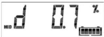
text_image
d 0.7 %BMV-702 and -712 only, when the auxiliary input is set to MID.
Deviation in percent of the measured midpoint voltage.
Battery bank midpoint deviation voltage
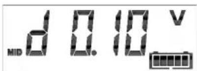
text_image
MID d 0.10 VBMV-702 and -712 only, when the auxiliary input is set to MID.
Deviation in Volts of the midpoint voltage.
2.2 Synchronising the BMV
For a reliable readout, the state of charge as displayed by the battery monitor has to be synchronised regularly with the true state of charge of the battery. This is accomplished by fully charging the battery.
In case of a 12V battery, the BMV resets to ‘fully charged’ when the following ‘charged parameters’ are met: the voltage exceeds 13.2V and simultaneously the (tail-) charge current is less than 4.0% of the total battery capacity (e.g. 8A for a 200Ah battery) during 3 minutes.
The BMV can also be synchronised (i.e. set to 'battery fully charged') manually if required. This can be achieved in normal operating mode by holding the + and – buttons simultaneously for 3 seconds, or in setup mode by using the SYNC option (see section 4.2.1, setting number 10).
By default, the BMV is configured to start-up in a synchronised state and will indicate a state of charge of 100%. This behaviour can be changed: see section 4.2.1, setting number 70.
If the BMV does not synchronise automatically, the charged voltage, tail current, and/or charged time may need adjustment. When the voltage supply to the BMV has been interrupted, the battery monitor must be resynchronised before it can operate correctly.
After having synchronised for the first time (automatically or manually), the BMV keeps track of the number of automatic synchronisations: see section 4.3, history item SYNCHRONISATIONS.
2.3 Common problems
No signs of life on the display
Probably the BMV is not properly wired. The UTP cable should be properly inserted at both ends, the shunt must be connected to the minus pole of the battery, and the positive supply cable should be connected to the plus pole of the battery with the fuse inserted.
The temperature sensor (when used) must be connected to the positive pole of the battery bank (one of the two wires of the sensor doubles as the power supply wire).
Charge and discharge current are inverted
Charge current should be shown as a positive value.
For example: 1.45A.
Discharge current should be shown as a negative value.
For example: -1.45A.
If charge and discharge current are inverted, the power cables on the shunt must be swapped: see the quick installation guide.
The BMV does not synchronise automatically
One possibility is that the battery never reaches the fully charged state. The other possibility is that the charged voltage setting should be lowered and/or the tail current setting should be increased.
See section 4.2.1.
The BMV synchronises too early
In solar systems or other applications with fluctuating charge currents, the following measures can be taken to reduce the probability for the BMV to reset prematurely to 100% state of charge:
a) Increase the “charged” voltage to only slightly below the absorption charge voltage (for example: 14.2V in case of 14.4V absorption voltage).
b) Increase the “charged” detection time and/or decrease the tail current to prevent an early reset due to passing clouds.
See section 4.2.1 for set up instructions.
Sync and battery icon are blinking
This means the battery is not synchronised. Charge the batteries and the BMV should sync automatically. If that doesn't work, review the sync settings. Or, if you know the battery is fully charged but don't want to wait until the BMV synchronises: press and hold the up and down button simultaneously, until you hear a beep.
See section 4.2.1.
3 FEATURES AND FUNCTIONALITY
3.1 Features of the four BMV models
The BMV is available in 4 models, each of which addresses a different set of requirements.
| BMV-700 | BMV-700H | BMV-702 and 712 | ||
| 1 | Comprehensive monitoring of a single battery | ● | ● | ● |
| 2 | Basic monitoring of an auxiliary battery | ● | ||
| 3 | Battery temperature monitoring | ● | ||
| 4 | Monitoring of the midpoint voltage of a battery bank | ● | ||
| 5 Use of alternate shunts | ● | ● | ● | |
| 6 | Automatic detection of nominal system voltage | ● | ● | ● |
| 7 | Suitable for high voltage systems | ● | ||
| 8 Several interface options | ● | ● | ● | |
Remark 1:
Features 2, 3 and 4 are mutually exclusive.
Remark 2:
The cable with integrated temperature sensor has to be purchased separately (part no: ASS000100000). This temperature sensor is not interchangeable with other Victron temperature sensors, as used with Multis or battery chargers.
3.2 Why should I monitor my battery?
Batteries are used in a wide variety of applications, mostly to store energy for later use. But how much energy is stored in the battery? No one can tell by just looking at it.
The service life of batteries depends on many factors. Battery life may be shortened by undercharging, overcharging, excessively deep discharges, excessive charge or discharge current, and high ambient temperature. By monitoring the battery with an advanced battery monitor, important feedback is given to the user so that remedial measures can be taken when necessary. Doing this, which extends battery life, the BMV will quickly pay for itself.
3.3 How does the BMV work?
The main function of the BMV is to follow and indicate the state of charge of a battery, in particular to prevent unexpected total discharge.
The BMV continuously measures the current flow in and out of the battery. Integration of this current over time (which, if the current is a fixed amount of Amps, boils down to multiplying current and time) gives the net amount of Ah added or removed.
For example: a discharge current of 10A during 2 hours will take 10 × 2 = 20Ah from the battery.
To complicate matters, the effective capacity of a battery depends on the rate of discharge and, to a lesser extent, on temperature.
And to make things even more complicated: when charging a battery more Ah has to be ‘pumped’ into the battery than can be retrieved during the next discharge. In other words: the charge efficiency is less than 100%.
3.3.1 About battery capacity and the rate of discharge
The capacity of a battery is rated in ampere-hours (Ah). For example, a lead acid battery that can deliver a current of 5A during 20 hours is rated at C_20 = 100Ah (5 x 20 = 100).
When the same 100Ah battery is discharged completely in two hours, it may only give C_2 = 56Ah (because of the higher rate of discharge).
The BMV takes this phenomenon into account with Peukert's formula: see section 5.1.
3.3.2 About charge efficiency (CEF)
The charge efficiency of a lead acid battery is almost 100% as long as no gas generation takes place. Gassing means that part of the charge current is not transformed into chemical energy, which is stored in the plates of the battery, but is used to decompose water into oxygen and hydrogen gas (highly explosive!). The ‘Amp-hours’ stored in the plates can be retrieved during the next discharge, whereas the ‘Amp-hours’ used to decompose water are lost.
Gassing can easily be observed in flooded batteries. Please note that the 'oxygen only' end of charge phase of sealed (VRLA) gel and AGM batteries also results in a reduced charge efficiency.
A charge efficiency of 95% means that 10Ah must be transferred to the battery to get 9.5Ah actually stored in the battery. The charge efficiency of a battery depends on battery type, age and usage.
The BMV takes this phenomenon into account with the charge efficiency factor: see section 4.2.2, setting number 06.
3.4 Several battery state of charge display options
The BMV can display both the Amp-hours removed ('consumed Amp-hours' readout, compensated for charge efficiency only) and the actual state of charge in percent ('state of charge' readout, compensated for charge efficiency and Peukert efficiency). Reading the state of charge is the best way to monitor the battery.
The BMV also estimates how long the battery can support the present load: the ‘time-to-go’ readout. This is the actual time left until the battery is discharged to the discharge floor. The factory discharge floor setting is 50% (see 4.2.2, setting number 16).
If the load is fluctuating heavily it is best not to rely on this reading too much since it is a momentary readout and must be used as a guideline only. We always encourage the use of the state of charge readout for accurate battery monitoring. The battery state of charge indicator (see chapter 7 “Display”) scales between the configured discharge floor and 100% state of charge and reflects the effective state of charge.
3.5 History data
The BMV stores events which can be used at a later date to evaluate usage patterns and battery health.
Select the history data menu by pressing ENTER when in normal mode (see section 4.3).
3.6 Use of alternative shunts
The BMV is supplied with a 500A / 50mV shunt. For most applications, this should be suitable; however the BMV can be configured to work with a wide range of different shunts. Shunts of up to 9999A, and/or 75mV can be used.
When using a shunt other than the one supplied with the BMV, please proceed as follows:
- Unscrew the PCB from the supplied shunt.
- Mount the PCB on the new shunt, ensuring that there is good electrical contact between the PCB and the shunt.
- Connect the shunt and BMV as shown in the quick installation guide.
- Follow the Setup wizard (section 1.1 and 1.2).
- After completion of the Setup wizard, set the proper shunt current and shunt voltage according to section 4.2.5, setting number 65 and 66.
- If the BMV reads a non-zero current even when there is no load and the battery is not being charged: calibrate the zero current reading (see section 4.2.1, setting number 09).
3.7 Automatic detection of nominal system voltage
The BMV will automatically adjust itself to the nominal voltage of the battery bank, immediately after completion of the setup wizard. The following table shows how the nominal voltage is determined, and how the charged voltage parameter (see section 2.2) is adjusted as a result.
| Measured voltage (V) | Assumed nominal voltage (V) | Charged voltage (V) | |
| BMV-700 & 702 & 712 | < 18 | 12 | 13.2 |
| 18 – 36 | 24 | 26.4 | |
| > 36 | 48 | 52.8 | |
| BMV-700H | Default nominal voltage: 144V | Default: 158.4V | |
In case of another nominal battery bank voltage (32V for example), the charged voltage must be set manually: see section 4.2.1, setting 02.
Recommended settings:
| Nominal battery voltage | Recommended Charged Voltage setting | |
| 12V | 13.2V | |
| 24V | 26.4V | |
| 36V | 39.6V | |
| 48V | 52.8V | |
| 60V | 66V | |
| 120V | 132V | |
| 144V | 158.4V | |
| 288V | 316.8V | |
3.8 Alarm, buzzer and relay:
On most of the BMV's readings an alarm can be triggered when the value reaches a set threshold. When the alarm becomes active the buzzer starts to beep, the backlight flashes and the alarm icon is visible in the display along with the current value.
The corresponding segment will also flash. AUX when a starter alarm occurs. MAIN, MID or TEMP for the corresponding alarm.
(When in the setup menu and an alarm occurs, the value causing the alarm will not be visible.)
An alarm is acknowledged when a button is pressed. However, the alarm icon is displayed as long as the alarm condition remains.
It is also possible to trigger the relay when an alarm condition occurs.
BMV-700 and -702
The relay contact is open when the coil is de-energised (NO contact), and will close when the relay is energised.
Factory default setting: the relay is controlled by the state of charge of the battery bank. The relay will be energised when the state of charge decreases to less than 50% (the ‘discharge floor’), and will be de-energised when the battery has been recharged to 90% state of charge.
See section 4.2.2.
The relay function can be inverted: de-energised becomes energised and vice versa. See section 4.2.2.
When the relay is energised, the current drawn by the BMV will increase slightly: see technical data.
BMV-712 Smart
The BMV-712 has been designed to minimize power consumption.
The alarm relay therefore is a bistable relay, and the current draw remains low whatever the position of the relay.
3.9 Interface options
3.9.1 PC Software
Connect the BMV to the computer with the VE.Direct to USB interface cable (ASS030530000) and download the appropriate software.
https://www.victronenergy.com/live/victronconnect:start
3.9.2 Large display and remote monitoring
The Color Control GX, a display featuring a 4.3" colour display, provides intuitive control and monitoring for all products connected to it. The list of Victron products that can be connected is endless: Inverters, Multis, Quattros, MPPT solar chargers, BMV, Skylla-i, Lynx Ion and more. The BMV can be connected to the Color Control GX with a VE.Direct cable. It is also possible to connect it with the VE.Direct to USB interface. Besides monitoring and controlling locally with the Color Control GX, the information is also forwarded to our free remote monitoring website: the VRM Online Portal. For more information, see the Color Control GX documentation on our website.
3.9.3 Custom integration (programming required)
The VE.Direct communications port can be used to read data and change settings. The VE.Direct protocol is extremely simple to implement.
Transmitting data to the BMV is not necessary for simple applications: the BMV automatically sends all readings every second. All the details are explained in this document:
https://www.victronenergy.com/upload/documents/Whitepaper-Data-communication-with-Victron-Energy-products_EN.pdf
3.10 Additional functionality of the BMV-702 and -712
In addition to the comprehensive monitoring of the main battery system, the BMV-702 and -712 have a second monitoring input. This secondary input has three configurable options, described below.
3.10.1 Auxiliary battery monitoring
Wiring diagram: see the quick installation guide. Fig 3
This configuration provides basic monitoring of a second battery, displaying its voltage. This is useful for systems with a separate starter battery.
3.10.2 Battery temperature monitoring
Wiring diagram: see the quick installation guide. Fig 4
The cable with integrated temperature sensor has to be purchased separately (part no: ASS000100000). This temperature sensor is not interchangeable with other Victron temperature sensors, as provided with Multis or battery chargers. The temperature sensor must be connected to the positive pole of the battery bank (one of the two wires of the sensor doubles as the power supply wire).
The temperature can be displayed in degrees Celsius or degrees Fahrenheit, see section 4.2.5, setting number 67.
The temperature measurement can also be used to adjust battery capacity to temperature, see section 4.2.5, setting number 68.
The available battery capacity decreases with temperature.
Typically, the reduction, compared to the capacity at 20^ C, is 18% at 0^ C and 40% at -20^ C.
3.10.3 Midpoint voltage monitoring
Wiring diagram: see the quick installation guide. Fig 5 - 12
One bad cell or one bad battery can destroy a large, expensive battery bank.
A short circuit or high internal leakage current in one cell for example will result in under charge of that cell and over charge of the other cells.
Similarly, one bad battery in a 24V or 48V bank of several series/parallel connected 12V batteries can destroy the whole bank.
Moreover, when cells or batteries are connected in series, they should all have the same initial state of charge. Small differences will be ironed out during absorption or equalise charging, but large differences will result in damage during charging due to excessive gassing of the cells or batteries with the highest initial state of charge.
A timely alarm can be generated by monitoring the midpoint of the battery bank. For more information, see section 5.1.
3.11 Additional functionality of the BMV-712 Smart
3.11.1 Automatic cycling through status items
The BMV-712 can be instructed to automatically cycle through the status items by keeping the minus button pressed for 3 seconds. This enables one to keep an eye on their system's status without the need to operate the BMV-712. Automatic cycling through status items is disabled again by pressing any of the buttons.
3.11.2 Turning Bluetooth On/Off
The BMV-712's on-board Bluetooth module can be turned on or off through the settings menu. See section 4.2.1, setting 71.
4 FULL SETUP DETAILS
4.1 Using the menus
(alternatively, use the VictronConnect app and smart phone)
Four buttons control the BMV. The function of the buttons depends on which mode the BMV is in.
| Button | Function | |
| When in normal mode | When in setup mode | |
| If backlight is off, press any button to restore backlight | ||
| SETUP | Press and hold for two seconds to switch to setup mode.The display will scroll the number and description of the selected parameter. | Press SETUP at any time to return to the scrolling text, and press again to return to normal mode.When pressing SETUP while a parameter is out of range, the display blinks 5 times and the nearest valid value is displayed. |
| SELECT | Press to switch to history menu.Press to stop scrolling and show the value. Press again to switch back to normal mode. | - Press to stop scrolling after entering the setup mode with the SETUP button.- After editing the last digit, press to end editing. The value is stored automatically.Confirmation is indicated by a short beep.- If required, press again to restart editing. |
| SETUP/ SELECT | Press and hold both SETUP and SELECT buttons simultaneously for three seconds to restore factory settings (disabled when setting 64, lock setup, is on, see section 4.2.5) | |
| + Move upwards | When not editing, press to move up to the previous parameter. | |
| When editing, this button will increment the value of the selected digit. | ||
| - | Move downwards | When not editing, press to move down to the next parameter. |
| When editing, this button will decrement the value of the selected digit. | ||
| BMV-712 only:Press and hold for three seconds (until the confirmation beep) to start automatic cycling through status items. | ||
| +/- | Press and hold both buttons simultaneously for three seconds to manually synchronise the BMV | |
When power is applied for the first time or when factory settings have been restored, the BMV will start the quick setup wizard: see section 1. Thereafter, if power is applied, the BMV will start in normal mode: see section 2.
4.2 Functions overview
The following summary describes all the parameters of the BMV.
- Press SETUP for two seconds to access these functions and use the + and - buttons to browse them.
- Press SELECT to access the desired parameter.
- Use SELECT and the + and – buttons to customize. A short beep confirms the setting.
- Press SETUP at any time to return to the scrolling text, and press again to return to normal mode.
4.2.1 Battery settings
- Battery capacity
Battery capacity in amp hours
| Default | Range | Step size |
| 200Ah | 1 – 9999Ah | 1Ah |
- Charged voltage
| The battery voltage must be above this voltage level to consider the battery as fully charged.The charged-voltage-parameter should always be slightly below the end of charge voltage of the charger (usually 0.2V or 0.3V below the ‘float’ voltage of the charger).See section 3.7 for recommended settings. |
BMV-700 / BMV-702 / BMV-712 Smart
| Default | Range | Step size |
| See table, sect 3.7 | 0 – 95V | 0.1V |
BMV-700H
| Default | Range | Step size |
| 158.4V | 0 – 384V | 0.1V |
03. Tail current
Once the charge current has dropped to less than the set tail current (expressed as percentage of the battery capacity), the battery is considered as fully charged.
Remark:
Some battery chargers stop charging when the current drops below a set threshold. The tail current must be set higher than this threshold.
| Default | Range | Step size |
| 4% | 0.5 – 10% | 0.1% |
04. Charged detection time
This is the time the charged-parameters (Charged voltage and Tail current) must be met in order to consider the battery fully charged.
| Default | Range | Step size |
| 3 minutes | 1 – 50 minutes | 1 minute |
05. Peukert exponent
When unknown it is recommended to keep this value at 1.25 (default) for lead acid batteries and change to 1.05 for Li-ion batteries. A value of 1.00 disables the Peukert compensation.
| Default | Range | Step size |
| 1.25 | 1 – 1.5 | 0.01 |
06. Charge Efficiency Factor
The Charge Efficiency Factor compensates for the Ah losses during charging.
100% means no loss.
| Default | Range | Step size |
| 95% | 50 – 100% | 1% |
07. Current threshold
When the current measured falls below this value it will be considered zero.
The current threshold is used to cancel out very small currents that can negatively affect the long term state of charge readout in noisy environments. For example if the actual long term current is 0.0A and due to injected noise or small offsets the battery monitor measures -0.05A, and in the long term the BMV can incorrectly indicate that the battery needs recharging. When the current threshold in this example is set to 0.1A, the BMV calculates with 0.0A so that errors are eliminated.
A value of 0.0A disables this function.
| Default | Range | Step size |
| 0.1A | 0 – 2A | 0.01A |
08. Time-to-go averaging period
Specifies the time window (in minutes) that the moving averaging filter works.
A value of 0 disables the filter and gives an instantaneous (real-time) readout; however the displayed value may fluctuate heavily. Selecting the longest time (12 minutes) ensures that only long term load fluctuations are included in the time-to-go calculations.
| Default | Range | Step size |
| 3 minutes | 0 – 12 minutes | 1 minute |
09. Zero current calibration
If the BMV reads a non-zero current even when there is no load and the battery is not being charged, this option can be used to calibrate the zero reading.
Ensure that there really is no current flowing into or out of the battery (disconnect the cable between the load and the shunt), then press SELECT.
10. Synchronise
This option can be used to manually synchronise the BMV.
Press SELECT to synchronise.
The BMV can also be synchronised when in normal operating mode by holding the + and - buttons simultaneously for 3 seconds.
4.2.2 Relay settings
Remark: thresholds are disabled when set at 0
11. Relay mode
DFLT Default mode. The relay thresholds Nos. 16 up to 31 can be used to control the relay.
CHRG Charger mode. The relay will close when the state of charge falls below setting 16 (discharge floor) or when the battery voltage falls below setting 18 (low voltage relay).
The relay will be open when the state of charge is higher than setting 17 (clear state of charge relay) and the battery voltage is higher than setting 19 (clear low voltage relay).
Application example: start and stop control of a generator, together with settings 14 and 15.
REM Remote mode. The relay can be controlled via the VE.Direct interface. Relay settings 12 and 14 up to 31 are ignored as the relay is under the full control of the device connected via the VE.Direct interface.
12. Invert relay
This function enables selection between a normally de-energised (contact open) or a normally energised (contact closed) relay. When inverted, the open and closed conditions as described in setting 11 (DFLT and CHRG), and settings 14 up to 31 are inverted.
The normally energised setting will slightly increase supply current in the normal operating mode.
Default Range
OFF: Normally de-energised OFF: Normally de-energised / ON: normally energised
13. Relay state (read only)
Displays whether the relay is open or closed (de-energised or energised).
Range
OPEN/CLSD
14. Relay minimum closed time
Sets the minimum amount of time that the CLOSED condition will remain present after the relay has been energised. (changes to OPEN and de-energised if the relay function has been inverted) Application example: set a minimum generator run time (relay in CHRG mode).
15. Relay-off delay
Sets the amount of time the ‘de-energise relay’ condition must be present before the relay opens.
Application example: keep a generator running for a while to better charge the battery (relay in CHRG mode).
| Default | Range | Step size |
| 0 minutes | 0 – 500 minutes | 1 minute |
16. SOC relay (Discharge floor)
When the state of charge percentage has fallen below this value, the relay will close.
The time-to-go displayed is the time to reach the discharge floor.
| Default | Range | Step size |
| 50% | 0 – 99% | 1% |
17. Clear SOC relay
When the state of charge percentage has risen above this value, the relay will open (after a delay, depending on setting 14 and/or 15). This value needs to be greater than the previous parameter setting. When the value is equal to the previous parameter the state of charge percentage will not close the relay.
| Default | Range | Step size |
| 90% | 0 – 99% | 1% |
18. Low voltage relay
When the battery voltage falls below this value for more than 10 seconds the relay will close.
19. Clear low voltage relay
When the battery voltage rises above this value, the relay will open (after a delay, depending on setting 14 and/or 15). This value needs to be greater than or equal to the previous parameter.
20. High voltage relay
When the battery voltage rises above this value for more than 10 seconds the relay will close.
21. Clear high voltage relay
When the battery voltage falls below this value, the relay will open (after a delay, depending on setting 14 and/or 15). This value needs to be less than or equal to the previous parameter.
| BMV-700 / BMV-702 / BMV 712 Smart | |||
| Default | Range | Step size | |
| 0V | 0 – 95V | 0.1V | |
| BMV-700H | |||
| Default | Range | Step size | |
| 0V | 0 – 384V | 0.1V | |
22. Low starter voltage relay -702 and -712 only
When the auxiliary (e.g. starter battery) voltage falls below this value for more than 10 seconds the relay will be activated.
23. Clear low starter voltage relay -702 and -712 only
When the auxiliary voltage rises above this value, the relay will open (after a delay, depending on setting 14 and/or 15). This value needs to be greater than or equal to the previous parameter.
24. High starter voltage relay -702 and -712 only
When the auxiliary (e.g. starter battery) voltage rises above this value for more than 10 seconds, the relay will be activated.
25. Clear high starter voltage relay -702 and -712 only
When the auxiliary voltage falls below this value, the relay will open (after a delay, depending on setting 14 and/or 15). This value needs to be less than or equal to the previous parameter.
Default
Range
Step size
0V 0 - 95V 0.1V
26. High temperature relay -702 and -712 only
When the battery temperature rises above this value for more than 10 seconds, the relay will be activated.
27. Clear high temperature relay -702 and -712 only
When the temperature falls below this value, the relay will open (after a delay, depending on setting 14 and/or 15). This value needs to be less than or equal to the previous parameter.
28. Low temperature relay -702 and -712 only
When the temperature falls below this value for more than 10 seconds, the relay will be activated.
29. Clear low temperature relay -702 and -712 only
When the temperature rises above this value, the relay will open (after a delay, depending on setting 14 and/or 15). This value needs to be greater than or equal to the previous parameter. See setting 67 for choosing between °C and °F.
Default
Range
Step size
0^ C -99- 99^ C 1^ C
0^ -146-210°F 1^
30. Mid voltage relay -702 and -712 only
When the midpoint voltage deviation rises above this value for more than 10 seconds, the relay will be activated. See section 5.2 for more information about the midpoint voltage.
31. Clear mid voltage relay -702 and -712 only
When the midpoint voltage deviation falls below this value, the relay will open (after a delay, depending on setting 14 and/or 15). This value needs to be less than or equal to the previous parameter.
Default
Range
Step size
0% 0 - 99%
0.1%
4.2.3 Alarm-Buzzer settings
Remark: thresholds are disabled when set at 0
32. Alarm buzzer
When set, the buzzer will sound an alarm. After a button is pressed the buzzer will stop sounding. When disabled the buzzer will not sound an alarm.
Default Range
ON ON/OFF
33. Low SOC alarm
When the state of charge falls below this value for more than 10 seconds the low SOC alarm is turned on. This is a visual and audible alarm. It does not energise the relay.
34. Clear low SOC alarm
When the state of charge rises above this value, the alarm is turned off. This value needs to be greater than or equal to the previous parameter.
| Default | Range | Step size |
| 0% | 0 – 99% | 1% |
35. Low voltage alarm
When the battery voltage falls below this value for more than 10 seconds the low voltage alarm is turned on. This is a visual and audible alarm. It does not energise the relay.
36. Clear low voltage alarm
When the battery voltage rises above this value, the alarm is turned off. This value needs to be greater than or equal to the previous parameter.
-
High voltage alarm - When the battery voltage rises above this value for more than 10 seconds the high voltage alarm is turned on. This is a visual and audible alarm. It does not energise the relay.
-
Clear high voltage alarm - When the battery voltage falls below this value, the alarm is turned off. This value needs to be less than or equal to the previous parameter.
BMV-700 / BMV-702 / BMV-712 Smart
| Default | Range | Step size |
| 0V | 0 – 95V | 0.1V |
BMV-700H
| Default | Range | Step size |
| 0V | 0 – 384V | 0.1V |
39. Low starter voltage alarm -702 and -712 only
When the auxiliary (e.g. starter battery) voltage falls below this value for more than 10 seconds the alarm will be activated. This is a visual and audible alarm. It does not energise the relay.
40. Clear low starter voltage alarm -702 and -712 only
When the auxiliary voltage rises above this value, the alarm is switched off. This value needs to be greater than or equal to the previous parameter.
41. High starter voltage alarm -702 and -712 only
When the auxiliary (e.g. starter battery) voltage rises above this value for more than 10 seconds, the alarm will be activated. This is a visual and audible alarm. It does not energise the relay.
42. Clear high starter voltage alarm -702 and -712 only
When the auxiliary voltage falls below this value, the alarm is switched off. This value needs to be less than or equal to the previous parameter.
| Default | ||
| 0V | 0 – 95V | 0.1V |
Range
Step size
43. High temperature alarm -702 and -712 only
When the battery temperature rises above this value for more than 10 seconds, the alarm will be activated. This is a visual and audible alarm. It does not energise the relay.
44. Clear high temperature alarm -702 and -712 only
When the temperature falls below this value, the alarm is switched off. This value needs to be less than or equal to the previous parameter.
45. Low temperature alarm -702 and -712 only
When the temperature falls below this value for more than 10 seconds, the alarm will be activated. This is a visual and audible alarm. It does not energise the relay.
46. Clear low temperature alarm -702 and -712 only
When the temperature rises above this value, the alarm is switched off. This value needs to be greater than or equal to the previous parameter.
See parameter 67 for choosing between °C and °F.
| Default | ||
| 0°C | -99 – 99°C | 1°C |
| 0°F | -146 – 210°F | 1°F |
Range
Step size
47. Mid voltage alarm -702 and -712 only
When the midpoint voltage deviation rises above this value for more than 10 seconds, the alarm will be activated. This is a visual and audible alarm. It does not energise the relay.
See section 5.2 for more information about midpoint voltage.
| Default | Range | Step size |
| 2% | 0 – 99% | 0.1% |
48. Clear mid voltage alarm -702 and -712 only
When the midpoint voltage deviation falls below this value, the alarm is switched off. This value needs to be less than or equal to the previous parameter.
| Default | Range | Step size |
| 1.5% | 0 – 99% | 0.1% |
4.2.4 Display settings
49. Backlight intensity
The intensity of the backlight, ranging from 0 (always off) to 9 (maximum intensity
| Default | Range | Step size | ||
| 5 | 0 – 9 | 1 | ||
50. Backlight always on
When set the backlight will not automatically turn off after 60 seconds of inactivity.
Default Range
OFF OFF/ON
51. Scroll speed
The scroll speed of the display, ranging from 1 (very slow) to 5 (very fast).
| Default | Range | Step size | ||
| 2 | 1-5 | 1 | ||
52. Main voltage display
Must be ON to display the voltage of the main battery in the monitoring menu.
53. Current display
Must be ON to display current in the monitoring menu.
54. Power display
Must be ON to display power in the monitoring menu.
55. Consumed Ah display
Must be ON to display consumed Ah in the monitoring menu.
56. State of charge display
Must be ON to display state of charge in the monitoring menu.
57. Time-to-go display
Must be ON to display time-to-go in the monitoring menu.
58 Starter voltage display -702 and -712 only
Must be ON to display the auxiliary voltage in the monitoring menu.
59. Temperature display -702 and -712 only
Must be ON to display the temperature in the monitoring menu.
60. Mid-voltage display -702 and -712 only
Must be ON to display the midpoint voltage in the monitoring menu.
Default Range
ON ON/OFF
4.2.5 Miscellaneous
61. Software version (read only)
The software version of the BMV
Resets all settings to factory default by pressing SELECT.
When in normal operating mode, factory settings can be restored by pressing SETUP and SELECT simultaneously for 3 seconds (only if setting 64, Lock setup, is off).
63. Clear history
Clears all history data by pressing SELECT.
64. Lock setup
When on, all settings (except this one) are locked and cannot be altered.
Default Range
OFF OFF/ON
65. Shunt current
When using a shunt other than the one supplied with the BMV, set to the rated current of the shunt.
Default Range Step size
500A 1 - 9999A 1A
66. Shunt voltage
When using a shunt other than the one supplied with the BMV, set to the rated voltage of the shunt.
Default Range Step size
50mV 1mV–75mV 1mV
67. Temperature unit
CELC Displays the temperature in °C.
FAHR Displays the temperature in °F.
Default Range
CELC CELC/FAHR
68. Temperature coefficient
This is the percentage the battery capacity changes with temperature, when temperature decreases to less than 20^ C (above 20^ C the influence of temperature on capacity is relatively low and is not taken into account). The unit of this value is “%cap/°C” or percent capacity per degree Celsius. The typical value (below 20^ C) is 1%cap/°C for lead acid batteries, and 0.5%cap/°C for Lithium Iron Phosphate batteries.
| Default | Range | Step size |
| 0%cap/°C | 0 – 2%cap/°C | 0.1%cap/°C |
69. Aux input
Sets the function of the auxiliary input:
START Auxiliary voltage, e.g. a starter battery.
MID Midpoint voltage.
TEMP Battery temperature.
The cable with integrated temperature sensor has to be purchased separately (part no: ASS000100000). This temperature sensor is not interchangeable with other Victron temperature sensors, as provided with Multis or battery chargers.
70. Start synchronised
When ON, the BMV will consider itself synchronised when powered-up, resulting in a state of charge of 100%. If set to OFF, the BMV will consider it unsynchronised when powered-up, resulting in a state of charge that is unknown until the first actual synchronisation.
Default Range
ON OFF/ON
71. Bluetooth mode (BMV-712 only)
Determines whether to enable Bluetooth. If turned OFF using the VictronConnect app, the Bluetooth functionality is not disabled until disconnected from the BMV. Note that this setting is only available when the firmware of the on-board Bluetooth module supports this functionality.
Default Range
ON OFF/ON
4.3 History data
The BMV tracks several parameters regarding the state of the battery which can be used to evaluate usage patterns and battery health.
Enter history data by pressing the SELECT button when in normal mode.
Press + or – to browse the various parameters.
Press SELECT again to stop scrolling and show the value.
Press + or – to browse the various values.
Press SELECT again to leave the historical menu and go back to normal operation mode.
The history data is stored in non-volatile memory, and will not be lost when the power supply to the BMV is interrupted.
| Parameter | Description |
| A dEEPEST di SCHR-9E | The deepest discharge in Ah. |
| b LAST di SCHR-9E | The largest value recorded for Ah consumed since the last synchronisation. |
| C RuErAGE di SCHR-9E | Average discharge depth |
| d CYCLES | The number of charge cycles. A charge cycle is counted every time the state of charge drops below 65%, then rises above 90% |
| E di SCHR-9ES | The number of full discharges. A full discharge is counted when the state of charge reaches 0%. |
| F CUI'ULATI uE AH | The cumulative number of Amp hours drawn from the battery. |
| G LO'EST uOLTAGE | The lowest battery voltage. |
| H HI GHEST uOLTAGE | The highest battery voltage. |
| I DAYS SINCE LAST CHARGE | The number of days since the last full charge. |
| J SYNCHRONI 2ATI OnS | The number of automatic synchronisations. A synchronisation is counted every time the state of charge drops below 90% before a synchronisation occurs. |
| L LO' uOLTAGE ALARIS | The number of low voltage alarms. |
| ii HIGH uOLTAGE ALARIS | The number of high voltage alarms. |
| P LO'EST AUH uOLTAGE | The lowest auxiliary battery voltage. |
| q HIGHEST AUH uOLTAGE | The highest auxiliary battery voltage. |
| r di SCHR-9ED EnEr9Y | The total amount of energy drawn from the battery in (k)Wh |
| S CHARGED EnEr9Y | The total amount of energy absorbed by the batteryin (k)Wh |
* BMV-702 and 712 only
5 MORE ABOUT PEUKERT'S FORMULA AND MIDPOINT MONITORING
5.1 Peukert's formula: battery capacity and discharge rate
The value which can be adjusted in Peukert's formula is the exponent n : see the formula below.
In the BMV Peukert's exponent can be adjusted from 1.00 to 1.50. The higher the Peukert exponent the faster the effective capacity ‘shrinks’ with increasing discharge rate. An ideal (theoretical) battery has a Peukert Exponent of 1.00 and has a fixed capacity; regardless of the size of the discharge current. The default setting for the Peukert exponent is 1.25. This is an acceptable average value for most lead acid batteries. Peukert's equation is stated below:
$$ C p = I ^ {n} \cdot t \quad \text { where Peukert's exponent } n = \frac {t _ {2} - \log \log_ {2}}{I _ {1} - \log \log_ {2}} $$
The battery specifications needed for calculation of the Peukert exponent are the rated battery capacity (usually the 20 h discharge rate ^1 ) and for example a 5h discharge rate ^2 . See below for an example of how to calculate the Peukert exponent using these two specifications.
5h rating
$$ _ {5 h} = 7 5 A h C $$
$$ t _ {1} = 5 h $$
$$ I _ {1} = \frac {7 5 A h}{5 h} = 1 5 A $$
20h rating
$$ _ {2 0 h} = A h C \quad \text { capacity }) $$
$$ \mathbf {t} _ {2} = 2 0 h $$
$$ I _ {2} = \frac {1 0 0 A h}{2 0 h} = 5 A $$
$$ \text { Peukert exponent }, n = \frac {\log 2 0 - \log 5}{\log 1 5 - \log 5} = \underline {{1 . 2 6}} $$
A Peukert calculator is available at
http://www.victronenergy.com/support-and-downloads/software/
Please note that Peukert's formula is no more than a rough approximation of reality, and that at very high currents, batteries will give even less capacity than predicted from a fixed exponent.
We recommend not to change the default value in the BMV, except in case of Li-ion batteries: See section 6.
5.2 Midpoint voltage monitoring
Wiring diagram: see the quick installation sheet. Fig 5-12
One bad cell or one bad battery can destroy a large, expensive battery bank.
A short circuit or high internal leakage current in one cell for example will result in under charge of that cell and over charge of the other cells.
Similarly, one bad battery in a 24V or 48V bank of several series/parallel connected 12V batteries can destroy the whole bank.
Moreover, when new cells or batteries are connected in series, they should all have the same initial state of charge. Small differences will be ironed out during absorption or equalise charging, but large differences will result in damage during charging due to excessive gassing of the cells or batteries with the highest initial state of charge.
A timely alarm can be generated by monitoring the midpoint of the battery bank (i. e. by splitting the string voltage in half and comparing the two string voltage halves).
Please note that the midpoint deviation will be small when the battery bank is at rest, and will increase:
a) at the end of the bulk phase during charging (the voltage of well charged cells will increase rapidly while lagging cells still need more charging),
b) when discharging the battery bank until the voltage of the weakest cells starts to decrease rapidly, and
c) at high charge and discharge rates.
5.2.1 How the % midpoint deviation is calculated
$$ \mathrm{d} (\%) = 100 ^ {*} (\mathrm{Vt} - \mathrm{Vb}) / \mathrm{V} $$
where:
d is the deviation in %
Vt is the top string voltage
Vb is the bottom string voltage
V is the voltage of the battery (V = Vt + Vb)
5.2.2 Setting the alarm level:
In case of VRLA (gel or AGM) batteries, gassing due to overcharging will dry out the electrolyte, increasing internal resistance and ultimately resulting in irreversible damage. Flat plate VRLA batteries start to lose water when the charge voltage approaches 15V (12V battery).
Including a safety margin, the midpoint deviation should therefore remain below 2% during charging.
When, for example, charging a 24V battery bank at 28.8V absorption voltage, a midpoint deviation of 2% would result in:
$$ \mathrm{Vt} = \mathrm{V} ^ {} \mathrm{d} / 1 0 0 ^ {} + \mathrm{Vb} = \mathrm{V} ^ {*} \mathrm{d} / 1 0 0 + \mathrm{V} - \mathrm{Vt} $$
Therefore:
$$ \mathrm{Vt} = \left(\mathrm{V} ^ {} (1 + \mathrm{d} / 1 0 0) / 2 = 2 8. 8 ^ {} 1. 0 2 / 2 \approx 1 4. 7 \mathrm{V} \right. $$
And:
$$ \mathrm{Vb} = \left(\mathrm{V} ^ {} (1 - \mathrm{d} / 1 0 0) / 2 = 2 8. 8 ^ {} 0. 9 8 / 2 \approx 1 4. 1 \mathrm{V} \right. $$
Obviously, a midpoint deviation of more than 2% will result in overcharging the top battery and undercharging the bottom battery.
Two good reasons to set the midpoint alarm level at not more than d = 2%.
This same percentage can be applied to a 12V battery bank with a 6V midpoint.
In case of a 48V battery bank consisting of 12V series connected batteries, the \% influence of one battery on the midpoint is reduced by half. The midpoint alarm level can therefore be set at a lower level.
5.2.3 Alarm delay
In order to prevent the occurrence of alarms due to short term deviations that will not damage a battery, the deviation must exceed the set value during 5 minutes before the alarm is triggered.
A deviation exceeding the set value by a factor of two or more will trigger the alarm after 10 seconds.
5.2.4 What to do in case of an alarm during charging
In case of a new battery bank the alarm is probably due to differences in initial state of charge. If d increases to more than 3%: stop charging and charge the individual batteries or cells separately first, or reduce charge current substantially and allow the batteries to equalize over time.
If the problem persists after several charge-discharge cycles:
a) In case of series-parallel connection disconnect the midpoint parallel connection wiring and measure the individual midpoint voltages during absorption charging to isolate batteries or cells which need additional charging.
b) Charge and then test all batteries or cells individually.
In case of an older battery bank which has performed well in the past, the problem may be due to:
a) Systematic under charge, more frequent charging or equalization charge needed (flooded deep cycle flat plate or OPzS batteries). Better and regular charging will solve the problem.
b) One or more faulty cells: proceed as suggested under a) or b).
5.2.5 What to do in case of an alarm during discharging
The individual batteries or cells of a battery bank are not identical, and when fully discharging a battery bank the voltage of some cells will start dropping earlier than others. The midpoint alarm will therefore nearly always trip at the end of a deep discharge.
If the midpoint alarm trips much earlier (and does not trip during charging), some batteries or cells may have lost capacity or may have developed a higher internal resistance than others. The battery bank may have reached the end of service life, or one of more cells or batteries have developed a fault:
a) In case of series-parallel connection, disconnect the midpoint parallel connection wiring and measure the individual midpoint voltages during discharging to isolate faulty batteries or cells.
b) Charge and then test all batteries or cells individually.
5.2.6 The Battery Balancer (see datasheet on our website)
The Battery Balancer equalizes the state of charge of two series connected 12V batteries, or of several parallel strings of series connected batteries. When the charge voltage of a 24V battery system increases to more than 27.3V, the Battery Balancer will turn on and compare the voltage over the two series connected batteries. The Battery Balancer will draw a current of up to 0.7A from the battery (or parallel connected batteries) with the highest voltage. The resulting charge current differential will ensure that all batteries will converge to the same state of charge.
If needed, several balancers can be paralleled.
A 48V battery bank can be balanced with three Battery Balancers.
6 LITHIUM IRON PHOSPHATE BATTERIES (LiFePO4)
LiFePO4 is the most commonly used Li-ion battery chemistry.
The factory default ‘charged parameters’ are in general also applicable to LiFePO_4 batteries.
Some battery chargers stop charging when the current drops below a set threshold. The tail current must be set higher than this threshold.
The charge efficiency of Li-ion batteries is much higher than of lead acid batteries: We recommend to set the charge efficiency at 99%.
When subjected to high discharge rates, LiFePO _4 batteries perform much better than lead-acid batteries. Unless the battery supplier advizes otherwise, we recommend setting Peukert's exponent at 1.05.
Important warning
Li-ion batteries are expensive and can be irreparably damaged due to over discharge or over charge.
Damage due to over discharge can occur if small loads (such as: alarm systems, relays, standby current of certain loads, back current drain of battery chargers or charge regulators) slowly discharge the battery when the system is not in use.
In case of any doubt about possible residual current draw, isolate the battery by opening the battery switch, pulling the battery fuse(s) or disconnecting the battery positive when the system is not in use.
A residual discharge current is especially dangerous if the system has been discharged completely and a low cell voltage shut down has occurred. After shutdown due to low cell voltage, a capacity reserve of approximately 1Ah per 100Ah battery capacity is left in a Li-ion battery. The battery will be damaged if the remaining capacity reserve is drawn from the battery. A residual current of 4mA for example may damage a 100Ah battery if the system is left in discharged state during more than 10 days (4mA x 24h x 10 days = 0.96Ah).
A BMV 700 or 702 draws 4mA from a 12V battery (which increases to 15mA if the alarm relay is energised). The positive supply must therefore be interrupted if a system with Li-ion batteries is left unattended during a period long enough for the current draw by the BMV to completely discharge the battery.
We strongly recommend to use the BMV-712 Smart, with a current draw of only 1mA (12V battery), irrespective of the position of the alarm relay.
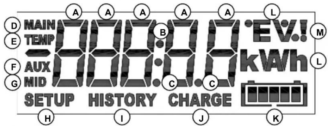
7 DISPLAY
Overview of the BMV's display.
text_image
MAIN TEMP A B C D E F G E AUX MID SETUP HISTORY CHARGE H I J K EV! kWh L MA The value of the selected item is displayed with these digits
(B) Colon
(c) Decimal separator
(D) Main battery voltage icon
E Battery temperature icon
(F) Auxiliary voltage icon
(G) Midpoint voltage icon
(H) Setup menu active
(I) History menu active
Battery needs to be recharged (solid), or BMV is not synchronised (blinking, together with K)
K Battery state of charge indicator (blinks when not synchronised)
(L) Unit of the selected item. e.g. W, kW, kWh, h, V, %, A, Ah, °C, °F
M Alarm indicator
Scrolling
The BMV features a scrolling mechanism for long texts. The scroll speed can be changed by modifying the setting scroll speed in the settings menu. See section 4.2.4. parameter 51
8 TECHNICAL DATA
| Supply voltage range (BMV-700 / BMV-702) | 6.5 ... 95 VDC |
| Supply voltage range (BMV-712) | 6.5 ... 70 VDC |
| Supply voltage range (BMV-700H) | 60... 385 VDC |
Supply current (no alarm condition, backlight off)
BMV-700/BMV-702
@Vin = 12 VDC 3mA
With relay energised 15mA
@Vin = 24 VDC 2mA
With relay energised 8mA
BMV-712 Smart
@Vin = 12 VDC 1mA
With relay energised
@Vin = 24 VDC 0.8mA
With relay energised
Fuse size on positive wire 1A, 20 x 5mm
BMV-700H
@Vin = 144 VDC 3mA
@Vin = 288 VDC 3mA
Input voltage range auxiliary battery (BMV-702) 0 ... 95 VDC
Input current range (with supplied shunt)
Operating temperature range
Readout resolution:
Voltage (0 ... 100V)
Voltage (100 ... 385V)
Current (0 ... 10A)
Current (10 ... 500A)
Current (500 ... 9999A) ±1A
Amp hours (0 ... 100Ah) ±0.1Ah
Amp hours (100 ... 9999Ah)
State of charge (0 ... 100%)
Time-to-go (0 ... 1h)
Time-to-go (1 ... 240h)
Temperature ±1°C/°F
Power (-100 ... 1kW)
Power (-100 ... 1kW)
Voltage measurement accuracy
Current measurement accuracy
Potential free contact
Mode Configurable
Default mode
Rating 1A up to 30VDC
0,2A up to 70VDC
1A up to max 50VAC
Dimensions:
Front panel
Body diameter 52mm
Overall depth 31mm
Net weight:
BMV 70g
Shunt 315g
Material
Body ABS
Sticker Polyester
1 SNELSTARTGIDS
6 LITHIUM-IJZERFOSFAATACCU'S (LiFePO4)
7 DISPLAY
Pairing-procedure: de standaard-pincode is 000000
text_image
BMV-702 STATUS HISTORY State of charge 85% Output Voltage 25.46V Current -7.5A Consumed Ah 25Ah Time remaining 5h 0m Input Starter battery 12.80V Delaytext_image
MAIN 12.13 VHulpaccuspanning
text_image
AUX 13.57 V Batteryhttps://www.victronenergy.com/live/victronconnect:start
https://www.victronenergy.com/upload/documents/Whitepaper-Data-communication-with-Victron-Energy-products_EN.pdf
04. Charged detection time
06. Charge Efficiency Factor
07. Current threshold
08. Time-to-go averaging period
14. Relay minimum closed time
18. Low voltage relay
20. High voltage relay
21. Clear high voltage relay
65. Shunt current (shunt stroom)
66. Shunt voltage (shuntspanning)
$$ t _ {2} = 2 0 h $$
$$ I _ {2} = \frac {1 0 0 A h}{2 0 h} = 5 A $$
$$ \text { Peukert exponent, } n = \frac {\log 2 0 - \log 5}{\log 1 5 - \log 5} = \underline {{1 . 2 6}} $$
http://www.victronenergy.com/support-and-downloads/software/
6 LITHIUM-IJZERFOSFAATACCU'S (LiFePO4)
text_image
MAIN TEMP A B C E E AUX M G MID SETUP HISTORY CHARGE H I J K EV! kWh M LStroom (0 ... 10A) ±0.01A
Stroom (10 ... 500A) ±0.1A
Stroom (500 ... 9999A) ±1A
Ampère-uren (0 ... 100Ah) ±0.1Ah
Ampère-uren (100 ... 9999Ah) ±1Ah
Laadstatus (0 ... 100%) ±0.1%
text_image
No 5M 12:35 PM BMV-702 STATUS HISTORY State of charge 85% Output Voltage 25.46V Current -7.5A Consumed Ah 25Ah Time remaining 5h 0m Input Starter battery 12.80V DelayAssistant de configuration (sinon, utilisez l'application VictronConnect et un Smartphone) :
text_image
MAIN 12.13 Vhttps://www.victronenergy.com/live/victronconnect:start
https://www.victronenergy.com/upload/documents/Whitepaper-Data-communication-with-Victron-Energy-products_EN.pdf
0^ -146-210°F 1^
Plage
Écart
30. Mid voltage relay -702 and -712 only (Relais de tension médiane -702 et -712 uniquement)
0^ -146-210°F 1^
Plage
Écart
71. Mode Bluetooth (BMV-712 uniquement)
Courant (10 ... 500A) ±0.1 A
Courant (500 ... 9999A) ±1 A
Ampères-heures (0 ... 100Ah) ±0.1 Ah
Ampères-heures (100 ... 9999Ah) ±1 Ah
https://www.victronenergy.com/live/ve.direct:ve.direct_to_bluetooth_smart_dongle
BMV-712 Smart:
https://www.victronenergy.com/live/victronconnect:start
text_image
BMW-702 STATUS HISTORY State of charge 85% Power Voltage 25.46V Current -7.5A Consumed Ah 25Ah Time remaining 5h 0m Power Starter battery 12.80V Batterytext_image
MAIN 12.13 Vhttps://www.victronenergy.com/live/victronconnect:start
https://www.victronenergy.com/upload/documents/Whitepaper-Data-communication-with-Victron-Energy-products_EN.pdf
text_image
MAIN TEMP A B E A A A L MAIN TEMP AUX MID SETUP HISTORY CHARGE EV! kWh L H I J KStrom (500 ... 9999A) ±1A
Amperestunden (0 ... 100Ah)
Amperestunden (100 ... 9999Ah)
Ladezustand (0 ... 100%)
text_image
BMV-702 STATUS HISTORY State of charge 85% Output Voltage 25.46V Current -7.5A Consumed Ah 25Ah Time remaining 5h 0m Input Starter battery 12.80V Relaytext_image
MAIN 12.13 VOFF: Norm. desenerg. / ON: Norm. energ.
http://www.victronenergy.com/support-and-downloads/software/
Corriente (10 ... 500 A) ±0.1 A
Corriente (500 ... 9.999 A) ±1 A
Amperios hora (0 ... 100 Ah) ±0.1 Ah
Amperios hora (100 ... 9.999 Ah) ±1 Ah
Estado de la carga (0 ... 100%) ±0.1%
Autonomia restante (0 ... 1 h)
Autonomia restante (1 ... 240 h) ±1 h
Temperatura ±1°C/°F
Potencia (-100 ... 1 kW) ±1 W
Potencia (-100 ... 1 kW) ±1 kW
https://www.victronenergy.com/live/ve.direct:ve.direct_to_bluetooth_smart_dongle
BMV-712 Smart:
Ladda ner appen VictronConnect (se "downloads" på vår hemsida) https://www.victronenergy.com/live/victronconnect:start
text_image
BMV-702 STATUS HISTORY State of charge 85% Output: Voltage 25.46V Current -7.5A Consumed Ah 25Ah Time remaining 5h 0m Input Starter battery 12.80V Recoverytext_image
MAIN 12.13 Vhttps://www.victronenergy.com/upload/documents/Whitepaper-Data-communication-with-Victron-Energy-products_EN.pdf
32. Alarm buzzer (Larmsummer)
68. Temperature coefficient (Temperaturkoefficient)
http://www.victronenergy.com/support-and-downloads/software/
text_image
MAIN TEMP A B E A A A L MAIN TEMP AUX MID SETUP HISTORY CHARGE EV! kWh L F C G H I J KStröm (500 ... 9999A) ±1A
Amperetimmar (0 ... 100Ah) ±0.1Ah
Amperetimmar (100 ... 9999Ah) ±1Ah
Laddningstillständ (0 ...100%) ±0.1%
Äterstående tid (0 ... 1h) ±0.1h
Äterstäende tid (1 ... 240h) ±1h
Temperatur ±1°C/°F
Effekt (-100 ... 1kW) ±1W
Effekt (-100 ... 1kW) ±1kW
EN: BMV connection for midpoint voltage
EN: BMV with temperature sensor (fuses not shown, BMV-702 and 712 only)
EN: BMV connection for midpoint voltage
EN: Midpoint voltage monitoring (fuses not shown, BMV-702 and 712 only)
PO Box 50016 | 1305 AA Almere | The Netherlands
General phone
: +31 (0)36 535 97 00
: sales@victronenergy.com
www.victronenergy.com