
BlueSolar Pro Remote Panel - Solar panel VICTRON ENERGY - Free user manual and instructions
Find the device manual for free BlueSolar Pro Remote Panel VICTRON ENERGY in PDF.


| Type | Remote panel for BlueSolar PWM-Pro charge controllers |
| Compatible controllers | BlueSolar PWM-Pro 12/24V 5A, 10A, 20A, 30A |
| Article number | SCC900300000 |
| Faceplate dimensions | 98 × 98 mm (3.86 × 3.86 inches) |
| Frame dimensions | 114 × 114 mm (4.49 × 4.49 inches) |
| Weight | 0.2 kg |
| Connector type | RJ45 |
| Maximum cable length | 20 m |
| Power consumption (backlight and alarm on) | Max. 65 mA |
| Power consumption (backlight on) | Max. 23 mA |
| Power consumption (backlight off) | Max. 15 mA |
| Ambient temperature range | -20°C to +70°C (-4°F to 158°F) |
| Display | LCD with monitoring data (battery voltage, PV power, load status, etc.) |
| Buttons | ESC, UP, DOWN, LEFT, RIGHT, OK |
| Communication | RS485 via RJ45 |
| Alarm | Audible alarm and warning LED for controller faults |
| Password protection | Yes (default password 000000) |
| Load control modes | Manual, Light On/Off, Light On+Timer, Time Control |
| Battery monitoring | State of charge, voltage, current, temperature, SOC |
| Installation | Panel mount, 4 screws; connection via standard RJ45 UTP cable |
Frequently Asked Questions - BlueSolar Pro Remote Panel VICTRON ENERGY
User questions about BlueSolar Pro Remote Panel VICTRON ENERGY
0 question about this device. Answer the ones you know or ask your own.
Ask a new question about this device
Download the instructions for your Solar panel in PDF format for free! Find your manual BlueSolar Pro Remote Panel - VICTRON ENERGY and take your electronic device back in hand. On this page are published all the documents necessary for the use of your device. BlueSolar Pro Remote Panel by VICTRON ENERGY.
USER MANUAL BlueSolar Pro Remote Panel VICTRON ENERGY
BlueSolar Pro Remote Panel
For BlueSolar PWM-Pro charge controllers 12/24V 5, 10, 20, 30A
Article number SCC900300000
Contents
- Important safety instructions .... 2
- Installation 2
3.Product features.... 3
3.1 General 3
3.2 Display 5
3.3 Buttons 6
- Monitoring 6
- Full setup details 8
5.1 Main menu 8
5.2 Device Information 8
5.3 Test Operation 8
5.4 Control Parameters ...... 9
5.5 Load Settings 10
5.6 Device Parameters ...... 12
5.7 Device Password 12
5.8 Charge mode 12
5.9 Factory reset.... 12
5.10 Failure Information .... 13
5.11 Meter parameters ...... 13
- Technical Specifications .... 13
- RS485 connector pinout 13
- Dimensions ...... 14
1. Important safety instructions
Read all instructions before starting the installation.
Keep the controller away from rain, exposure, severe dust, vibration, corrosive gas and intense electromagnetic interference.
2. Installation
Please see section 8 for mounting dimensions
Connection to the BlueSolar PWM-Pro charge controller:
The panel must be connected to the controller with a standard RJ45 UTP cable.

3. Product features
3.1. General

RS485 communication and power interface

Warning LED
The warning indicator LED flashes in case of failure of the connected charge controller.
Audible alarm
The audible failure alarm can be activated or deactivated.
Communication LED
Indicates communication status when the display is connected with the charge controller.
3.2. Display
After connecting the remote panel, the default monitoring display will be shown:
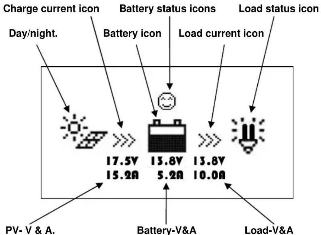
Day and night icons
Night, day. If the voltage of the solar array is above 1V, the daytime icon is shown.
Battery icon
The battery icon shows the state of charge of the battery. For this function the correct battery capacity must be set (see section 5.4) and all loads must connected to the load output (i.e. not directly to the battery).
Note: When the battery is fully discharged, the icon displayed is

Battery status icons

Normal voltage.

der voltage

Over discharge
Load status icon

- Load output "on"

ad output "off"
3.3. Buttons
![graph LR A["ESC"] --> B["Triangle"] B --> C["Triangle"] C --> D["Right Triangle"] D --> E["OK"]](/content/2026/05/1080767/images/d2d75ec7e4aebc42b4ebfaef31c279d3f3aa9f575fe2244b537968c9f7ea67cc.jpg)
Operation is visualized in the schematic diagram below:
![graph TD A["Main menu"] -->|OK| B["Browse subpages"] B -->|OK| C["Edit parameters"] C -->|ESC| A B -->|ESC| A](/content/2026/05/1080767/images/caf15dda0f680730282fda0cd719f0dec8e902fc72bb5191975c2d999d47a5fb.jpg)
4. Monitoring
The default monitoring display and monitoring subpages can be accessed with the UP/DOWN and LEFT/RIGHT buttons. See the diagram on the next page.
![graph TD A["BSC12/24 xxA<br>Month-Day-year<br>H.M.S"] --> B["Char. Energy<br>Day: 0000.00 kWh<br>Mon: 00000.00 kWh<br>Total: 00000.00 kWh"] B --> C["DisCh. Energy<br>Day: 0000.00 kWh<br>Mon: 00000.00 kWh<br>Total: 00000.00 kWh"] C --> D["Battery<br>Vol: 000.0V<br>Cur: -000.0A<br>SOC: XX%"] D --> E["…](/content/2026/05/1080767/images/cacf3167411c3d8e40017c5c5d019d86698d73640bb7ff5194979b7f0aa895ab.jpg)
5. Full setup details
5.1. Main menu
When in monitoring mode, the main menu is accessed by pressing the ESC button.
The UP and DOWN buttons are used to browse through the main menu:
1 Monitoring
2 Device information
3 Test operation
4 Control parameters
5 Load set
6 Device parameters
7 Device password
8 Charge mode
9 Factory reset
10 Failure information
11 Meter parameters
The OK and ESC buttons are respectively used to enter or exit the corresponding pages of the menu items.
A password must be entered to change settings.
When on a settings page, press OK to access the password page and fill in the password to enable changing of settings.
The default password is 000000
5.2 Device information
The charge controller model, ratings and serial number are displayed (press the DOWN button to display the serial number).
5.3 Test Operation
When the load output is set on manual control (default setting, see section 5,5), the output can be switched ON or OFF with the orange switch button on the Charge Controller. The low voltage cut-off is also operational.
The manual control function is disabled when other load output settings are chosen (see section 5.5).
However, when other load output settings have been chosen, the load output can be tested (i.e. switched ON and OFF) after switching back to Manual Control.
5.4 Control Parameters
The table below shows the list of battery related parameters that can be modified.
(press the DOWN or UP button to scroll through the parameters)
| Parameter | Default setting | |||
| Battery type Gel Sealed | (AGM) | Flooded | User defined | |
| Battery capacity (Ah) 200Ah 1~9999 | ||||
| Temperature compensation coefficient | -3mV/°C per 2V cell 0~9 | |||
| Rated voltage (system voltage) Auto 1 | 2V/24V | |||
| Over voltage load disconnect 16.0V 9~ | 17V | |||
| Charge limit (highest charge voltage including temp. compensation) | 15.0V 9~17V | |||
| Over voltage load reconnect 15.0V 9~ | 17V | |||
| Equalize charge —— 14.6V 14.8V | 9~17V | |||
| Boost charge (absorption charge) | 14.2V | 14.4V | 14.6V | 9~17V |
| Float charge | 13.8V | 13.8V | 13.8V | 9~17V |
| Boost trigger voltage (starts new charge cycle) | 13.2V 9~17V | |||
| Low voltage load reconnect | 12.6V 9~17V | |||
| Under voltage warning reset 12.2V 9~ | 17V | |||
| Under voltage warning | 12.0V 9~17V | |||
| Low voltage load disconnect (nominal value at 25°C) | 11.1V 9~17V | |||
| Discharge limit (lowest low voltage load disconnect including temp. compensation) | 10.6V 9~17V | |||
| Equalize duration | —— | 2 hrs. | 2 hrs. | 0~3 hrs. |
| Boost/absorption duration | 2 hrs. | 2 hrs. | 2 hrs. | 0~3 hrs. |
Multiply voltages by 2 for a 24V system
5.5 Load output setting
The load output setting options are shown below:
![graph TD A["Manual Control\n◎Light On/Off\n◎Light On+Timer\n◎Time Control"] <--> B["Manual Control\nDefault: ON"] C["Manual Control\n◎Light On/Off\n◎Light On+Timer\n◎Time Control"] <--> D["Light On/Off\nOn: 0.5V DeT: 10M\nOff: 0.4V DeT: 10M"] E["Manual Control\n◎Light On/Off\n◎Light On+Timer\n◎Time…](/content/2026/05/1080767/images/324a3ef91650a49068944a84e6fafd1f1ccba34318c9ace51bbf0c9850e7b192.jpg)
Option 1: Manual Control
When the load output is set on Manual Control (default setting), the output can be switched ON or OFF with the orange switch button on the Charge Controller. The low voltage cut-off is also operational.
Option 2: Light On/Off
This is a simple load output On/Off option, based on the solar input voltage of the Controller (= output voltage of the solar panel).
- When, at dusk, the input voltage of the Controller becomes lower than the light On voltage (default 0.50V), the load output is switched on.
- When, at dawn, the input voltage of the Controller becomes higher than the light Off voltage (default 0.40V), the load output is switched off.
- In order to prevent unwanted switching a confirmation time (DeT) can be set: default 10 minutes, range 0 – 99 minutes.
Option 3: Light On+Timer
This option allows for a pre-set On-time after dusk and a pre-set Off-time before dawn.
The dusk and dawn switching moments and confirmation time are set as under option 2.
The remaining parameters are set as follows:
- NightTime: initial setting of the night duration, the controller will subsequently adjust NightTime to the actual duration of the night.
- On Time 1: On period after dusk.
- On Time 2: On period before dawn.

Option 4: Time control
This option uses the internal clock (see section 5.6) to set one (Time1 only) or two on-time periods.
5.6 Device Parameters
The first screen displays the software version and communication ID number of the Charge Controller.
The second screen allows setting of the backlight timer, and local date & time (use the DOWN button to go to the second screen).
The above data are stored in the Charge Controller.
Device Parameter
Ver: VX.XX
ID : XXX
Device Parameter
Bklight: 60S
Month-Day-Year
H:M:S
5.7 Device Password
The password is needed to change settings of the charge controller. The default password is "000000". The password is stored in the Charge Controller
5.8 Charge mode
This page is intended for future applications. Please do not change.
5.9 Factory reset
Allows reset of the charge controller to the default settings.
5.10 Failure Information
Displays failures such as Over Voltage, Over Load or Short Circuit. (automatic reset when the fault is corrected).
E
5.11 Parameters
The first screen displays the type, software version and serial number of the remote meter.
The second screen allows modification of
- Switch-Pages (refresh time interval of the monitoring pages, default 0 seconds)
- Backlight duration (default 20 seconds).
- Audible alarm ON/OFF (default OFF).
6 Technical Specifications
| Self-consumption | backlight and acoustic alarm on max. 65mA |
| Backlight on max. 23mA | |
| Backlight off max. 15mA | |
| Faceplate dimensions | 98 × 98 mm / 3.86 × 3.86 inch |
| Frame dimensions | 114 × 114 mm / 4.49 × 4.49 inch |
| Connector type | RJ45 |
| Cable length | Max. 20 m |
| Weight | 0.2 Kg |
| Ambient Temperature | -20°C~+7°C / -4°F~158°F |
7 RS-485 connector pinout:
| Pin No. | |
| 1 | Power: +12V |
| 2 | RS485 B |
| 3 | RS485 A |
| 4 | GND |
| 5 | GND |
| 6 | RS485 A |
| 7 | RS485 B |
| 8 | Power: +12V |

8 Dimensions:

Victron Energy Blue Power
Distributor:
Serial number:
Version : 02
Date : 01 September 2014
Victron Energy B.V.
De Paal 35 | 1351 JG Almere
PO Box 50016 | 1305 AA Almere | The Netherlands
General phone : +31 (0)36 535 97 00
Customer support desk : +31 (0)36 535 97 03
Fax : +31 (0)36 535 97 40
E-mail : sales@victronenergy.com
www.victronenergy.com


- BLUESOLAR PRO REMOTE PANEL
- CONTENTS
- IMPORTANT SAFETY INSTRUCTIONS
- INSTALLATION
- CONNECTION TO THE BLUESOLAR PWM-PRO CHARGE CONTROLLER
- PRODUCT FEATURES
- GENERAL
- WARNING LED
- AUDIBLE ALARM
- COMMUNICATION LED
- DISPLAY
- DAY AND NIGHT ICONS
- BATTERY ICON
- BATTERY STATUS ICONS
- LOAD STATUS ICON
- BUTTONS
- MONITORING
- FULL SETUP DETAILS
- MAIN MENU
- 5.2 DEVICE INFORMATION
- 5.3 TEST OPERATION
- 5.4 CONTROL PARAMETERS
- 5.5 LOAD OUTPUT SETTING
- OPTION 1: MANUAL CONTROL
- OPTION 2: LIGHT ON/OFF
- OPTION 3: LIGHT ON+TIMER
- OPTION 4: TIME CONTROL
- 5.6 DEVICE PARAMETERS
- 5.7 DEVICE PASSWORD
- 5.8 CHARGE MODE
- 5.9 FACTORY RESET
- 5.10 FAILURE INFORMATION
- 5.11 PARAMETERS
- 6 TECHNICAL SPECIFICATIONS
- 7 RS-485 CONNECTOR PINOUT
- 8 DIMENSIONS
- VICTRON ENERGY BLUE POWER
Brand : VICTRON ENERGY
Model : BlueSolar Pro Remote Panel
Category : Solar panel