
VE.Bus Smart Dongle - Uncategorized VICTRON ENERGY - Free user manual and instructions
Find the device manual for free VE.Bus Smart Dongle VICTRON ENERGY in PDF.


| Product Type | VE.Bus Smart Dongle (Bluetooth accessory for inverter/chargers) |
| Brand | Victron Energy |
| Model | VE.Bus Smart Dongle |
| Input Voltage Range | 8 – 70 Vdc |
| Current Draw (Standby) | <6 mA (BLE not connected, VE.Bus connected, no VE.Smart network) |
| Current Draw (Active) | <9 mA (BLE connected, VE.Bus connected, joining VE.Smart network) |
| Operating Temperature | -20 to +50°C / 0 to 120°F |
| Humidity | Max. 95% (non-condensing) |
| Protection Grade | IP20 |
| Material | ABS, matt black |
| Dimensions (L x W x H) | 106 x 81 x 42.5 mm |
| Connectivity | Bluetooth (BLE) and RJ45 (VE.Bus port) |
| Compatible Inverter/Chargers | All with VE.Bus port (single, parallel, 3-phase) |
| Battery Voltage Sensing | Yes (8-70 Vdc range) |
| Battery Temperature Sensing | Yes (internal sensor or optional external sensor) |
| VE.Smart Networking | Yes (transmits battery voltage and temperature data) |
| Remote Control (via VictronConnect) | On/Off/Charger-only, AC input current limit |
| Remote Monitoring (via VictronConnect) | AC and DC parameters, device status, warnings/alarms |
| Firmware Update | Via VictronConnect app |
| LED Indicators | Blue and red LEDs for status and connection |
| Mounting | Adhesive pad or screw holes |
| Included Accessories | Terminal block, red (+) and black (-) wire with eye terminals and inline fuse |
| Optional Accessories | RJ45 UTP cable, external temperature sensor (BMV-712/702) |
Frequently Asked Questions - VE.Bus Smart Dongle VICTRON ENERGY
User questions about VE.Bus Smart Dongle VICTRON ENERGY
0 question about this device. Answer the ones you know or ask your own.
Ask a new question about this device
Download the instructions for your Uncategorized in PDF format for free! Find your manual VE.Bus Smart Dongle - VICTRON ENERGY and take your electronic device back in hand. On this page are published all the documents necessary for the use of your device. VE.Bus Smart Dongle by VICTRON ENERGY.
USER MANUAL VE.Bus Smart Dongle VICTRON ENERGY
This manual is also available in HTML5.
Table of Contents
- Introduction ...... 1
- Installation 2
2.1. What's in the box 2
2.2. Installation without external battery sensor 2
2.3. Installation with an external battery sensor 3
2.4. Updating firmware 4
2.5. VE.Smart Networking 5
- Operation 6
3.1. LED Status codes 6
3.2. Inverter/charger control and monitoring 6
3.3. Usage as a battery sensor 7
3.4. Usage with a GX device 7
- Specifications 9
- Troubleshooting 10
- Appendix ...... 11
6.1. Dimensions ...... 11
6.2. Firmware overview 11
1. Introduction
The VE.Bus Smart dongle is a Bluetooth accessory for inverter/chargers and inverters* with a VE.Bus port.
The dongle has the following features and functionalities:
- The dongle can remotely control the inverter/charger via Bluetooth and the VictronConnect app. The inverter/charger can be switched to on, off or charger-only and the AC input current limit can be adjusted.
- The dongle can remotely monitor the inverter/charger via Bluetooth and the VictronConnect app. The AC and DC parameters, device status, warnings or alarms can be monitored.
- The dongle can be connected to a single inverter/charger or multiple inverter/chargers set up in parallel and/or 3-phase.
- The dongle measures the battery temperature and voltage.
- The dongle can act as a battery temperature and voltage sensor for an inverter/charger and/or for VE.Smart Networking.
- The dongle can be connected to an external temperature sensor, rather than using its own (default) temperature sensor.

Note that the dongle cannot be used to configure an inverter/charger. Read the VictronConnect VE.Bus manual for more specific information on configuring an inverter/charger.
*) In the remainder of this document, we will refer to inverter/chargers instead of both inverter/chargers and inverters. If the dongle is used with an inverter, the charger-related features will not be available, such as monitoring AC parameters, switching a unit to "charger only" mode or adjusting the AC input current limit.
2. Installation
2.1. What's in the box
A. VE.Bus Smart Dongle.
B. Removable terminal block with screw terminals.
C. Black battery (-) connection wire with 10mm eye terminal.
D. Red battery (+) connection wire with 10mm eye terminal and inline fuse.


What's not in the box
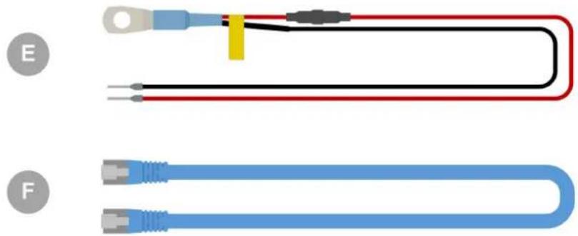
E. Temperature sensor for BMV-712 Smart and BMV-702. This temperature sensor can be used as an optional external temperature sensor. Note that the temperature sensor is shipped with the label "CAUTION: BMV702 only!". This caution can be ignored for use with the VE.Bus Smart dongle.
F. UTP RJ45 cable. This cable is required to connect the VE.Bus Smart Dongle to the inverter/charger or inverter. This cable needs to be purchased separately.
2.2. Installation without external battery sensor
This is the default installation method, whereby the dongle's internal temperature sensor is used.
-
Remove the connection terminal block from the dongle.
-
Connect the red power wire to the B+ terminal of the terminal block.
- Connect the black power wire to the B-terminal of the terminal block.
-
Connect the eye terminal of the black power wire to the negative terminal of the battery.
-
Connect the eye terminal of the red power wire to the positive terminal of the battery.
-
For battery temperature sensing, mount the dongle on top or on the side of the battery, using the dongle's adhesive mounting. If battery temperature sensing is not required, the dongle can be mounted near the battery using adhesive mounting or screws.
-
Plug the terminal block into the dongle.
-
Connect the dongle RJ45 terminal to the inverter/charger RJ45 terminal using an RJ45 UTP cable.
![graph TD A["Multi-Plan 8"] -->|A| B["U-2 Bus Smart Ducts"] A -->|B| C["Mobile Device"] A -->|C| D["Device"] A -->|D| E["Bluetooth"] A -->|E| F["Smart Phone"]](/content/2026/05/850506/images/c13ec80c093f737615b650002e6c95e8a909a9559562e3d4dbe50ba5a175fed5.jpg)
ID Description
| A Inverter/charger or inverter with VE.Bus port. | |
| B Fuse. | |
| C Battery. | |
| D VE.Bus Smart dongle affixed to the battery housing. | |
| E RJ45 UTP cable. | |
| F | Smartphone communicating via the VictronConnect app and Bluetooth with the VE.Bus Smart dongle. |
2.3. Installation with an external battery sensor
This is an optional installation method, whereby an external temperature sensor is used instead of the dongle's internal temperature sensor.
This installation requires the Temperature sensor for BMV-712 Smart and BMV-702. Note that this temperature sensor is a different temperature sensor than the one that is included with the inverter/charger. It needs to be purchased separately.
Note that the red power wire included with the dongle is not used in this installation. The red power wire will be replaced by the red wire of the temperature sensor.
- Remove the connection terminal block from the dongle.
- Connect the temperature sensor red wire to the B+ terminal of the terminal block.
- Connect the temperature sensor black wire to the T-terminal of the terminal block.
- Connect the black power wire to the B-terminal of the terminal block.
- Connect the eye terminal of the black power wire to the negative terminal of the battery.
-
Connect the temperature sensor eye terminal to the positive terminal of the battery.
-
Mount the dongle on the battery using the dongle's adhesive mounting, or mount it near the battery using screws or the adhesive mounting.
-
Plug the terminal block into the dongle.
-
Connect the dongle RJ45 terminal to the inverter/charger RJ45 terminal using an RJ45 UTP cable.
![graph TD A["Device 1"] --> B["Battery"] B --> C["Mobile Phone"] C --> D["Wireless Signal Generator"] D --> E["E Battery"] E --> F["F Bluetooth"] F --> G["Mobile Phone"] style A fill:#333,stroke:#fff,color:#fff style B fill:#999,stroke:#000,color:#fff style C fill:#ff9,stroke:#000,color:#fff style D…](/content/2026/05/850506/images/95634cb3bc97cf3cccb6c657ad58df660d8417c85ed4c0d2a175b750645c697d.jpg)
| ID Description | |
| A Inverter/charger or inverter with VE.Bus port. | |
| B Temperature sensor for BMV-712 Smart and BMV-702 | |
| C Fuse. | |
| D Battery. | |
| E VE.Bus Smart dongle affixed to the battery housing. | |
| F RJ45 UTP cable. | |
| G | Smartphone communicating via the VictronConnect app and Bluetooth with the VE.Bus Smart dongle. |
2.4. Updating firmware
Before using the dongle, ensure that its firmware, the inverter/charger firmware and the VictronConnect app version are all up to date.
- Update the inverter/charger to the most recent firmware version. Note that this needs to be at least firmware version xxxx415 or higher (or version xxxx419 or higher for full functionality).
- Make sure you are using the most recent version of the VictronConnect app.
- Update the firmware version of the dongle. Do this by connecting to it using the VictronConnect app. On the first connection, the VictronConnect app will likely indicate that the firmware needs to be updated. To update the dongle, follow the prompts by the VictronConnect app.
- To perform a manual firmware update or to check if the dongle has the most up-to-date firmware, go to the product settings page via the cog symbol in the top right-hand corner and then click on the 3-dot symbol in the top right-hand corner of the setting page and select "product info".

Be aware that the functionality and features of the dongle are related to its firmware version. For more information on the different firmware versions, see chapter Firmware overview [11].

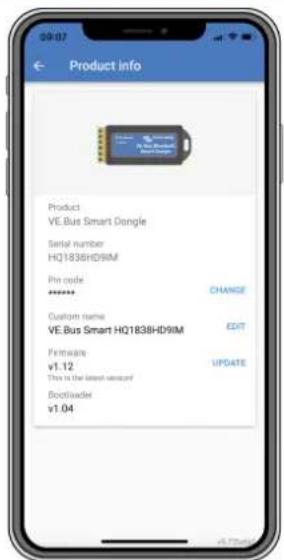
VictronConnect firmware update and product info screens.
2.5. VE.Smart Networking
The dongle supports VE.Smart Networking. When the dongle is part of VE.Smart Networking it can transmit battery temperature and battery voltage data to the network.
To add or set up VE.Smart Networking, navigate to the VictronConnect dongle settings page by clicking the cog symbol ✪ in the top right-hand corner. On the settings page select "VE.Smart Networking". You have two choices: create a new network or join an existing one.
When the dongle is part of VE.Smart Networking, this is indicated by a ⬆ symbol on the dongle VictronConnect overview page. See the orange circle in the image below on the right. When clicking on the symbol, you can check if the dongle is transmitting to the network and what type of data it is transmitting.

VictronConnect VE. Smart networking screens.

For more information on VE.Smart Networking also see the VE.Smart Networking manual.
3. Operation
When the dongle is connected to an inverter/charger and the inverter/charger has been switched on via its main power switch, it takes a bit of time before the dongle detects the inverter/charger. It is initially listed in the VictronConnect device list as a VE.Bus Smart dongle. Once the detection is complete, it will be listed as an inverter/charger. Note that it might be necessary to refresh the device list before the dongle is listed as an inverter/charger.
When the dongle is not connected to an inverter/charger, it is listed as a VE.Bus Smart Dongle. The dongle can be used without being connected to an inverter/charger. In this scenario, it operates as a voltage and temperature sensor and can be used for battery monitoring in VE.Smart Networking.

VictronConnect screens without and with inverter/charger connected.
The dongle can operate as a primary and as a background information source. It will assume either role automatically depending on whether a GX device is connected to the inverter/charger.
3.1. LED Status codes
| Blue LED Red LED Bluetooth | connection State | Dongle state | |
| Slow blinking Off Not connected The dongle is operational and ready to connect to the VictronConnect app. | |||
| On Off Connected The dongle is operational and is connected to the | VictronConnect app. | ||
| Off Off Not connected The dongle is not operational. Probably because it is | not powered, check the fuse or the wires between the dongle and the battery connection. | ||
| Fast blinking(alternating) | Fast blinking(alternating) | Not connected Firmware update. | |
| On Slow blinking Connected Firmware update. | |||
| On Fast blinking Uploading Firmware update. | |||
| Fast blinking Off Programming Firmware update. | |||
| On On Disabled The dongle is not functional (hardware error). The | dongle is not visible in the VictronConnect app and will not transmit battery temperature and voltage to the inverter/charger. | ||
3.2. Inverter/charger control and monitoring
The dongle can control and monitor the inverter/charger via the VictronConnect app.
The "overview" page contains the following:
- The inverter/charger can be turned on, off or set to charger-only mode via the switch symbol as indicated in the below image.
- The AC input limit of the inverter/charger can be adjusted via the dial symbol as indicated in the below image.
- Battery voltage, current and temperature are shown.
- The device status is shown.
More detailed inverter/charger information can be seen on the "detailed" page.

VictronConnect app "overview" and "detailed" screens.

Note that if a Digital Multi Contol panel (DMC) is connected to the same system as the dongle, the DMC will override the on/off/charger-only and current limit control features of the dongle. The dongle can only monitor the battery and inverter/charger parameters and act as a temperature and voltage sensor but cannot control the inverter/charger.
3.3. Usage as a battery sensor
The dongle measures the battery temperature and voltage:
- The battery temperature measurement allows the inverter/charger, or charge sources that are connected to VE.Smart Networking, to adjust the charge voltage to compensate for battery temperature.
- The battery voltage measurement allows the inverter/charger, or charge sources that are connected to VE.Smart Networking, to adjust the charge voltage to compensate for cable voltage losses that can occur during charging.
For more information about temperature and voltage compensation, see the inverter/charger manual.

Note that the inverter/charger does not use the dongle temperature and voltage measurements if the inverter/charger is connected to a GX device and a CANbus battery (smart battery). The data from the smart battery will override the data from the dongle.
3.4. Usage with a GX device
In systems with an inverter/charger and GX device but no other source of temperature and voltage, the data from the dongle will be used by the inverter/charger and the GX device.
In systems with a GX device, where another source of temperature and voltage data, e.g. from a CANbus battery (smart battery), the data from the smart battery will override the data from the dongle. In this scenario, the data from the smart battery is used by the inverter/charger and GX device. The dongle will still provide live information via its VictronConnect interface, but the system will use the data provided by the smart battery.
A GX device has priority over the dongle and should always be able to access all data. When power is applied to the dongle, or after a firmware update, the dongle will start up in background mode. The VE.Bus communication ports will be monitored for 30 seconds. If no GX device is detected, the dongle will switch to primary mode, and all supported data will be available. While switching modes, VictronConnect will temporarily indicate an "unknown" VE.Bus state. The dongle continuously monitors the VE.Bus for GX device activity. It will switch itself to background mode as soon as a GX device is detected or changes to primary mode when a GX is not detected.
The dongle monitors the VE.Bus to check if a GX device is supplying the inverter/charger with battery voltage and temperature data. It takes around 4 minutes after power-on or a reset before the dongle decides whether or not to transmit the battery voltage and temperature.
Due to restrictions in the VE.Bus communication protocol, only one device can access inverter/charger data at a time. When connecting with the VictronConnect app to the dongle while a GX device is connected, only the battery temperature and voltage and inverter/charger state are displayed, and the AC voltage, current, and power readings are missing.

VictronConnect screens when the dongle is connected to a GX device.
4. Specifications
| VE.Bus Smart Dongle Specifications | |
| Operating Input voltage range (Vbat) 8 – 70Vdc | |
| Current draw (@12V) - BLE not connected to VictronConnect, VE.Bus connected | Not joining a VE.Smart network <6mA Joining a VE.Smart network <9mA |
| Current draw (@12V) BLE connected to VictronConnect, VE.Bus connected | Not joining a VE.Smart network <7mA Joining a VE.Smart network <9mA |
| Operating temperature -20 to +50°C / 0 to 120°F | |
| Humidity Max. 95% (non-condensing) | |
| Protection grade IP20 | |
| Material and colour ABS, matt black |
5. Troubleshooting
Q: I only see a battery page screen in the VictronConnect app, but I do not see inverter/charger pages.
A: The dongle is not communicating with the inverter/charger. Check if it is plugged into the inverter/charger via an RJ45 UTP cable. Or, if it is plugged in, check the integrity of the RJ45 cable.
Q: I cannot see the inverter/charger data; only the battery data is displayed in the VictronConnect app.
A: Check if the inverter/charger has been turned on via its main switch, and check if the dongle is plugged into the inverter/charger via an RJ45 UTP cable. Or, if it is plugged in, check the integrity of the RJ45 cable.
Q: Can the dongle be used together with the Digital Multi Control panel (DMC)?
A: Yes, but in this scenario, the dongle cannot switch the inverter/charger to on, off or to charger-only, only the DMC can.
Q: Can the dongle be used together with a VE.Bus BMS?
A: Yes, but in this scenario, the dongle cannot switch the inverter/charger to on, off or to charger-only, only the VE.Bus BMS can. If full functionality of the dongle is required, use a VE.Bus BMS V2 instead.
Q: It is not possible to change the AC current limit.
A: Update the inverter/charger firmware to version xxxx419 or higher.
Q: What are the terminal connections marked "CD" and "Relay" used for?
A: These connections have no function and are not used.
Q: The dongle is measuring a too low battery voltage and an external battery sensor is used. The inverter/charger is overcharging the batteries as a result of this.
A: Check that the B- wire is connected to the battery minus. If this wire is not connected the dongle measures a too low battery voltage. See chapter Installation with an external battery sensor [3].
Q: The dongle battery voltage reading is approximately 0.6V too high in a 12V system, 1.2V in a 24V and 2.4V in a 48V system. The inverter/charger is undercharging the batteries as a result of this.
A: The dongle is faulty.

See also the VictronConnect manual and the VE.Smart Networking manual.
6. Appendix
6.1. Dimensions

6.2. Firmware overview
The VictronConnect app version, the dongle firmware version and the inverter/charger firmware version all will dictate the functionality and features of the dongle.
| VE.BusSmart dongle firmware version | Victron Connect version | Minimal VE.Bus firmware version | Feature added |
| 4.80 415 | Battery voltage sense.Temperature sense. | ||
| 1.08 5.36 419 | AC input current limit control.On/off/charger-only control.VE.Smart Networking. | ||
| 1.09 5.36 419 | Overview page.Hide the input current limit button when the inverter/charger is off. | ||
| 1.10 5.42 419 Support for the MultiPlus-II 2x120V split phase models. | |||
| 1.11 5.45 419 Bug fixes. | |||
| 1.12 5.70 419 Support for the VE.Bus BMS V2. | |||


- TABLE OF CONTENTS
- INTRODUCTION
- THE DONGLE HAS THE FOLLOWING FEATURES AND FUNCTIONALITIES
- INSTALLATION
- WHAT'S IN THE BOX
- WHAT'S NOT IN THE BOX
- INSTALLATION WITHOUT EXTERNAL BATTERY SENSOR
- INSTALLATION WITH AN EXTERNAL BATTERY SENSOR
- UPDATING FIRMWARE
- VE.SMART NETWORKING
- OPERATION
- LED STATUS CODES
- INVERTER/CHARGER CONTROL AND MONITORING
- USAGE AS A BATTERY SENSOR
- USAGE WITH A GX DEVICE
- SPECIFICATIONS
- TROUBLESHOOTING
- APPENDIX
- FIRMWARE OVERVIEW
Brand : VICTRON ENERGY
Model : VE.Bus Smart Dongle
Category : Uncategorized