
CT20TDR - Measuring equipment VOLTCRAFT - Free user manual and instructions
Find the device manual for free CT20TDR VOLTCRAFT in PDF.
| Product type | Cable tester |
| Brand | Voltcraft |
| Model | CT20TDR |
| Dimensions (L x W x H) | 195 x 90 x 40 mm |
| Weight | approx. 585 g |
| Power supply | 9 V battery (monoblock) |
| Connections | RJ-45, RJ-11, F |
| Tested cable types | Shielded, unshielded CAT3, CAT4, CAT5, CAT5E, CAT6, CAT7, coaxial |
| Length measurement range | 1 – 350 m (via TDR) |
| Length measurement accuracy | ±5 % |
| Test modes | LAN, TEL (telephone), COAX, TONE (localization), LENGTH |
| Display | LCD screen with adjustable backlight |
| Memory | Up to 8 results (LAN/TEL), 4 results (COAX/LENGTH) |
| Protection | Against overvoltages and transient sound signals |
| Operating conditions | 0 to +50 °C, 10 – 90 % RH |
| Storage conditions | -10 to +60 °C, 10 – 90 % RH |
| Included accessories | Remote measurement terminal, 2 F/BNC adapters, 2 Western RJ-45/RJ-11 reducers, TAE adapter (RJ-11-TAE), belt clip, carrying case, tripod mount, 9 V battery, instruction manual |
| Maintenance and cleaning | Soft, antistatic, lint-free cloth |
| Safety | Do not use on live installations; indoor use only |
| Repairability | Repair by a professional or specialized workshop |
Frequently Asked Questions - CT20TDR VOLTCRAFT
User questions about CT20TDR VOLTCRAFT
0 question about this device. Answer the ones you know or ask your own.
Ask a new question about this device
Download the instructions for your Measuring equipment in PDF format for free! Find your manual CT20TDR - VOLTCRAFT and take your electronic device back in hand. On this page are published all the documents necessary for the use of your device. CT20TDR by VOLTCRAFT.
USER MANUAL CT20TDR VOLTCRAFT
These Operating Instructions accompany this product. They contain important information on setting up and using the device. You should refer to these instructions, even if you are buying this product for someone else.
Please retain these Operating Instructions for future use! A list of the contents can be found in the Table of contents, with the corresponding page number, on page 23.

Abb. 1
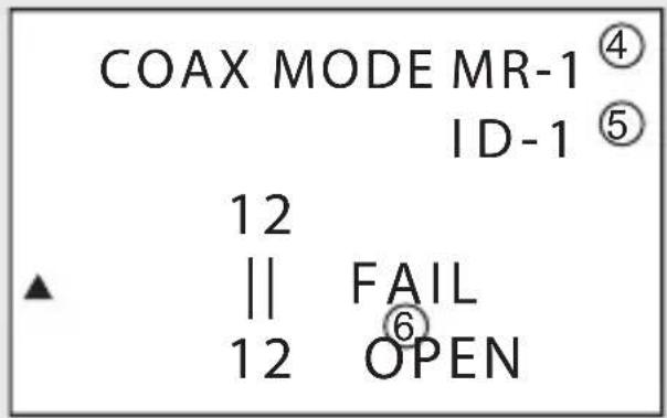
Abb. 3
1 Modus, Kabeltyp
2 Adern
natural_image
Simple line drawing of a rocket with motion lines and a labeled section (no text or symbols)Abb. 4
Abb. 5
Anschlüsse ....RJ-45, RJ-11, F
Kabeltypen......geschirmt, ungeschirmt
CAT3, CAT4, CAT5, CAT5E, CAT6, CAT7, Coax
- Introduction......24
- Intended use....25
- Controls....26
- Signs and symbols 28
- Safety instructions 28
- Scope of delivery....30
- Inserting/replacing batteries 31
- Belt clip....31
- Tripod holder 31
- General use....32
- Device settings 34
- LAN mode (LAN cable) 35
- TEL mode (telephone cable) 36
- COAX mode (coaxial cable) 38
- TONE mode (locate mode)....39
- LENGTH mode....40
- Cleaning and care 41
- Disposal....41
- Technical data 42
1. INTRODUCTION
Dear Customer,
In purchasing this Voltcraft® product, you have made a very good decision for which we would like to thank you.
Voltcraft® - In the field of measuring, charging and network technology, this name stands for high-quality products which perform superbly and which are created by experts whose concern is continuous innovation.
From the ambitious hobby electronics enthusiast to the professional user, products from the Voltcraft® brand family provide the optimum solution even for the most demanding tasks. And the remarkable feature is: we offer you the mature technology and reliable quality of our Voltcraft® products at an almost unbeatable price-performance ratio. In this way, we aim to establish a long, fruitful and successful co-operation with our customers.
We wish you a great deal of enjoyment with your new Voltcraft® product!
All company names and product names are trademarks of their respective owners. All rights reserved.
2. INTENDED USE
Use this cable tester to test 2- to 8-pin cables and connector shielding with the following connections: RJ45, RJ11 and F connectors.
The device has 5 test modes: LAN cable mode, telephone cable mode, coax cable mode, locate mode and length mode.
Length and fault location is possible with cable lengths of 1 - 350 m.
The display shows the test results.
Only conduct measurements on voltage-free systems.
The cable tester is designed for battery operation only.
The device is intended exclusively for indoor use, do not use outdoors. Avoid contact with moisture – such as via use in bathrooms, etc. – at all costs.
This product complies with the statutory national and European requirements.
For safety and approval purposes (CE), you must not rebuild and/or modify this product. If you use the product for purposes other than those described above, the product may be damaged. In addition, improper use can cause hazards such as short circuiting, fire, electric shock etc. Read the instructions carefully and keep them. Make this product available to third parties only together with its operating instructions.

Heed all safety instructions and information in this manual.
3. CONTROLS
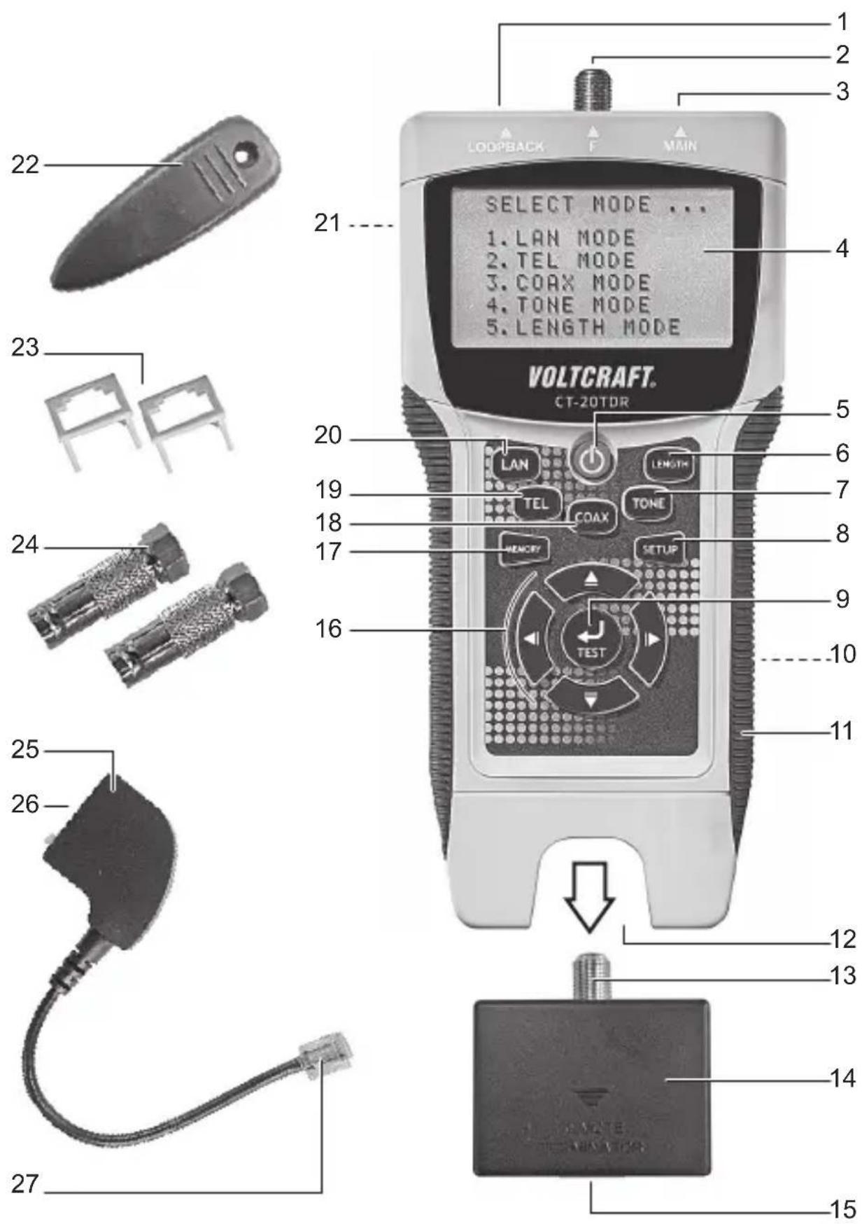
1 RJ-45 jack LOOPBACK
2 F connector F
3 RJ-45 jack MAIN
4 Display
5 On/off button
6 LENGTH button
7 TONE button
8 SETUP button
9 TEST button
10 Battery compartment (on the back)
11 Grip surface (on both sides)
12 Remote test port jack
13 F connector
14 Remote test port
15 RJ-45 jack
16 Navigation buttons (left, up, right, down)
17 MEMORY button
18 COAX button
19 TEL button
20 LAN button
21 Clip fastener
22 Belt clip
23 Western reduction insert RJ-45/RJ-11
24 Adaptor F/BNC
25 TAE adaptor (RJ-11-TAE)
26 TAE jack
27 RJ-11 connector
Not depicted:
- Tripod holder
- Belt clip screw
4. SIGNS AND SYMBOLS

An exclamation mark in a triangle indicates important instructions in this operating manual which absolutely have to be observed.
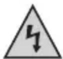
The triangle containing a lightning symbol warns of danger of an electric shock or of the impairment of the electrical safety of the device.

The symbol can be found when you are to be given tips and information on operation.
This device is CE-compliant and meets the necessary European directives.
5. SAFETY INSTRUCTIONS
Read the user manual thoroughly and pay special attention to the safety instructions. We accept no liability for personal injury or property damage resulting from failure to heed the safety instructions and/or improper use as described in this user manual. In such cases, the warranty is also made void.

a) Persons / Product
- Do not use with live power equipment! Connect the battery before operation.
- The cable tester may be used only to test voltage-free cables. Before measuring, always verify that there is no voltage present (risk of fatal injury)!
- This product is a precision instrument. Do not drop it or subject it to any blows.
- For installations in industrial facilities, follow the accident prevention regulations for electrical systems and equipment of the government safety organization or the corresponding authority for your country.
- Do not operate the device immediately after transferring it from a cold to a warm room. This can cause condensation which may, under adverse circumstances, destroy the device. Leave the device turned off until it has reached room temperature.
- This product is not a toy. Keep it out of the reach of children and pets.
- Do not leave packaging materials unattended. Packaging materials may prove a fatal toy in the hands of children.
- Shield the product from extreme temperatures, direct sunlight, strong shocks, high moisture, wetness, flammable gases, fumes and solvents.
- Do not subject the product to mechanical stress.
-
Cease use of the product immediately and protect it from inadvertent use if safe operation is no longer possible. Safe operation is no longer guaranteed if the product:
-
is visibly damaged,
- no longer functions properly,
- was stored for an extended period under unfavorable conditions or
-
was exposed to excessive transport stress.
-
Handle the product with care. The product can be damaged by blows of any kind and by being dropped, even from a low height.
- Heed all safety instructions and user manuals of third-party devices that the product is connected to.
b) Batteries / rechargeable batteries
- Heed correct polarity when inserting batteries / rechargeable batteries.
- Remove all batteries / rechargeable batteries from the device for periods of disuse to prevent damage to the device due to battery leakage. Leaking or damaged batteries / rechargeable batteries may cause acid burns in case of contact with skin. Wear protective gloves when handling damaged batteries / rechargeable batteries.
- Store batteries / rechargeable batteries out of the reach of children. Do not leave batteries / rechargeable batteries unattended, as children or pets may swallow them.
- Do not dismantle, short-circuit or throw batteries / rechargeable batteries into fire. Never attempt to charge non-rechargeable batteries. Risk of explosion!
c) Miscellaneous
- Consult a professional if you require assistance with product operation, safety or connection.
- Maintenance work, adjustments and repairs may be carried out only by a professional or at a specialist workshop.
Should you have questions concerning correct product connection or operation, or should other questions arise that this user manual does not address, please do not hesitate to contact our technical support or a third-party professional.
Voltcraft ^® , Lindenweg 15, D-92242 Hirschau, Tel. +49 96 04 / 40 87 80.
6. SCOPE OF DELIVERY
- Cable tester
- Remote test port
- 2 x F/BNC adaptor
• 2 x Western reduction insert RJ-45/RJ-11
• TAE adaptor (RJ-11-TAE) - Belt clip
- Bag
- Tripod holder
- 9V block battery
- User manual
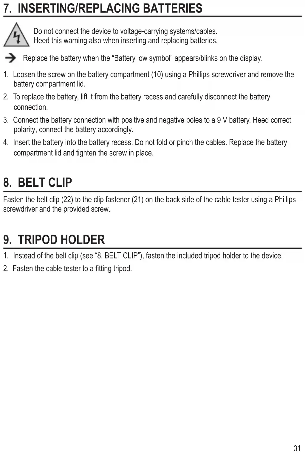
7. INSERTING/REPLACING BATTERIES
Do not connect the device to voltage-carrying systems/cables.
Heed this warning also when inserting and replacing batteries.
→ Replace the battery when the “Battery low symbol” appears/blinks on the display.
- Loosen the screw on the battery compartment (10) using a Phillips screwdriver and remove the battery compartment lid.
- To replace the battery, lift it from the battery recess and carefully disconnect the battery connection.
- Connect the battery connection with positive and negative poles to a 9 V battery. Heed correct polarity, connect the battery accordingly.
- Insert the battery into the battery recess. Do not fold or pinch the cables. Replace the battery compartment lid and tighten the screw in place.
8. BELT CLIP
Fasten the belt clip (22) to the clip fastener (21) on the back side of the cable tester using a Phillips screwdriver and the provided screw.
9. TRIPOD HOLDER
- Instead of the belt clip (see "8. BELT CLIP"), fasten the included tripod holder to the device.
- Fasten the cable tester to a fitting tripod.
a) Turning on/off
-
Push the on/off button (5) to turn on the cable tester. An audible signal sounds, provided audible signals have not been deactivated under settings (see "11. DEVICE SETTINGS"). After the welcome message, "SELECT MODE..." appears on the display.
-
Push the on/off button again to turn off the cable tester. The display goes out.
→ After 5 minutes without any input, the cable tester turns off automatically. In locate mode ("TONE MODE") after 30 minutes.
b) Navigating the menu
Use the navigation buttons (16) to navigate the menu when the device is turned on:
- ▲ (up), ▶(right), (down), (left)
c) Selecting a test mode
The following test modes are available:
- LAN MODE: LAN cable test
- TEL MODE: telephone cable test
- COAX MODE: coax cable test
- TONE MODE: locate mode
- LENGTH MODE: check/measure cable lengths
Select a test mode using the buttons LAN (20), TEL (19), COAX (18), TONE (7) and LENGTH (6). All test modes are described in the corresponding chapters.
d) Memory function
The cable tester can save test and measuring readings:
- LAN MODE, TEL MODE: max. 8 memory slots
- COAX MODE, LENGTH MODE: max. 4 memory slots
Saving test / measuring readings:
While the reading you wish to save is shown on the display, push and hold the MEMORY button (17) for ca. 2 seconds. After the button is released, the display will briefly show "MR-X". Here, "X" stands for the memory slot (for example, MR-5, memory slot 5).

Once all memory slots are filled, the last memory slot will be filled by each new saved reading.
Viewing test / measuring readings:
- Select the desired test mode.
- Push and hold the MEMORY button for ca. 4 seconds. Use the navigation buttons (up, down) to select the number of conductors:
Deleting entries:
- Select the desired test mode.
- Push and hold the MEMORY button for ca. 4 seconds.
- Push the TEST button (9) and confirm the confirmation prompt "ALL CLEAR?" with "YES" or "NO" with the navigation buttons (left, right). Once the data is deleted, the display shows "MR-0".
e) Remote test port
The remote test port can be used in combination with the test modes. Remove the remote test port connector (14) from the remote test port jack (12). After use and disconnecting the cable, reinsert the remote test port connector into the jack.

Additional remote test port connectors for this product are available as equipment under the order number 409235.
f) Adaptors/inserts
The cable tester includes various adaptors/inserts:
- Western reduction insert RJ-45/RJ-11 (23) : Reduction from RJ-45 to RJ-11
- F/BNC adaptor (24) : F connector to BNC
- TAE adaptor (RJ-11-TAE) (25) : RJ-11 to TAE
11. DEVICE SETTINGS
Turn on the cable tester. Access the setup menu by pushing the SETUP button (8). Navigate the menu using the navigation buttons (16). Settings are saved after selection until the cable tester is turned off (exception: reset to default settings).

To permanently save settings, push and hold the MEMORY button for ca. 1 second after selection. After the button is released, the display will briefly show "MR-SET".
Review the following menu overview for device settings:
Menu item Setting procedure
| 1. UNIT Set display unitM (meter), FT (feet) | |
| 2. LAN Length Adj Calibrate LAN cable length for known cable lengthUse the length setting when you know the cable length.Connect the cable to the RJ-45 jack MAIN (3).– Measure the length using the TEST button (9) and access submenu.– Calibrate length using "+" and "-" . "+" increases the value, "-" decreases the value. Push and hold navigation buttons to increase setting speed.– Push and hold the MEMORY button for ca. 2 seconds to save the value.The display shows “MR-SET”. | |
| 3. COAX Length Adj Calibrate coax cable length for known cable lengthUse the length setting when you know the cable length.Connect the cable only to the F connector F (2).– Measure the length using the TEST button (9) and access submenu.– Calibrate length using "+" and "-" . "+" increases the value, "-" decreases the value. Push and hold navigation buttons to increase setting speed.– Push and hold the MEMORY button for ca. 2 seconds to save the value.The display shows “MR-SET”. | |
| 4. Buzzer Turn key tone on/off“ON” (key tone on), “OFF” (key tone off) | |
| 5. Backlight Turnbacklight on/off“ON” (display backlight on), “OFF” (display backlight off) | |
| 6. Restore Default Reset cable tester to default– Push TEST button and use the navigation buttons to confirm (“YES”) or cancel (“NO”). |
LAN mode: Test/measure LAN cables.
Review the following display overview for LAN mode before beginning testing:
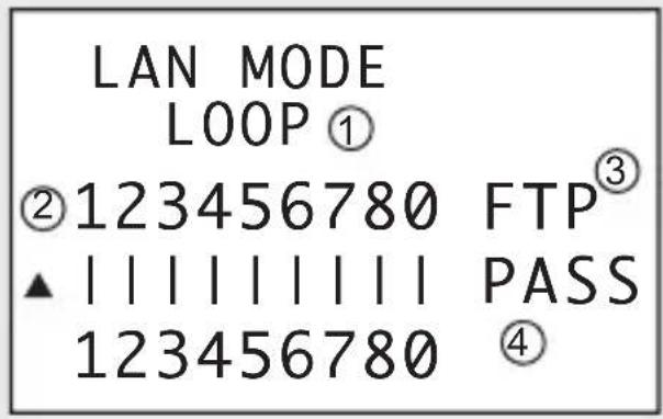
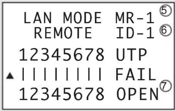
III. 1
1 Mode: "LOOP" or "REMOTE" (with remote test port)
2 Conductors
3 Cable type: FTP + 0 (shielded) or UTP (not shielded)
4 Result: "PASS" (positive result), "FAIL" (negative result)
5 Memory slot
6 ID display for remote test port
7 In case of "FAIL" (negative) reading: "OPEN" (open circuit), "SHORT" (short-circuited), "CROSS" (incorrect connection), "SPLIT" (split, not for remote test port! Min. length: 1 m)
a) Connection – LOOPBACK
Connect one cable end to the RJ-45 jack MAIN and the other to the RJ45 jack LOOPBACK (1).
b) Connection – Remote test port
For installed cables.
Connect one cable end to the RJ-45 jack MAIN and the other to the RJ-45 jack (15) on the remote test port (14).
c) Conducting a test
- Turn on the cable tester and push the LAN button. Or select "1. LAN MODE" using the navigation buttons and confirm with the TEST button.
- Push the LAN or TEST button to begin testing. The test result can be read on the display. See III. 1.
- By negative reading "FAIL": the conductors in question blink on the display.
- In case of "FAIL" with "OPEN": The distance (from the cable end) to the interrupted point.
- In case of "FAIL" with "CROSS": the conductors in question are shown blinking in their current position.
- In case of "FAIL" with "SPLIT" or "SHORT": the conductors in question blink.
- Remote test port: In case of "PASS", the remote test port's ID is displayed (i.e. 1) and the remote test port beeps. For a negative result, the ID is shown as "ID-?".
13. TEL MODE (TELEPHONE CABLE)
TEL mode: Test telephone cables.
Review the following display overview for telephone mode before beginning testing:
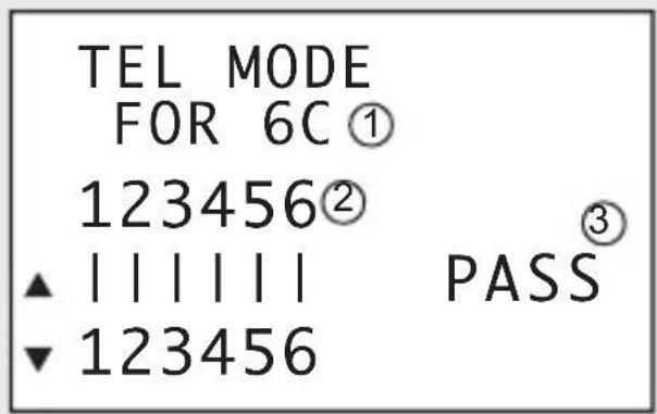
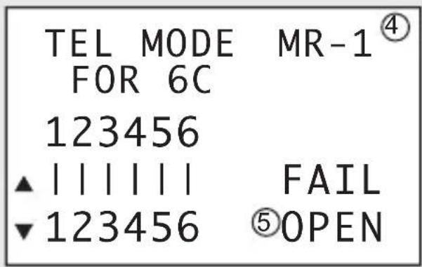
III. 2
1 Mode, number of conductors
2 Conductors
3 Result: "PASS" (positive result), "FAIL" (negative result)
4 Memory slot
5 In case of "FAIL" (negative) reading: "OPEN" (open circuit), "SHORT" (short-circuited), "CROSS" (incorrect connection, "FAIL" is not displayed)
a) Connection – LOOPBACK
- To connect, you will need the Western reduction insert RJ-45/R-J11 (23) and the TAE adaptor (RJ-11-TAE).
- Insert the reduction insert into the RJ-45 jack MAIN and the RJ-45 jack LOOPBACK. Align the inserts' connector guide edges to those of the RJ45 jacks.
- Connect the TAE jack on the telephone cable to the TAE jack on the TAE adaptor (25). Connect one cable end to the RJ-45 jack MAIN and the other to the RJ-45 jack LOOPBACK.
→ The remote test port is not needed to test telephone cables.
b) Conducting a test
- Turn on the cable tester and push the TEL button. Or select "2. TEL MODE" using the navigation buttons and confirm with the TEST button.
- Use the navigation buttons (up, down) to select the number of conductors:
- "2C" (two conductors), "4C" (four conductors), "6C" (six conductors)
- Push the TEST button to begin testing. The test result can be read on the display. See III. 2.
- By negative reading "FAIL": the conductors in question blink on the display.
- In case of "CROSS": the conductors in question are shown blinking in their current position.
- In case of "SHORT": the conductors in question blink.
√COAX mode: Test coaxial cables.
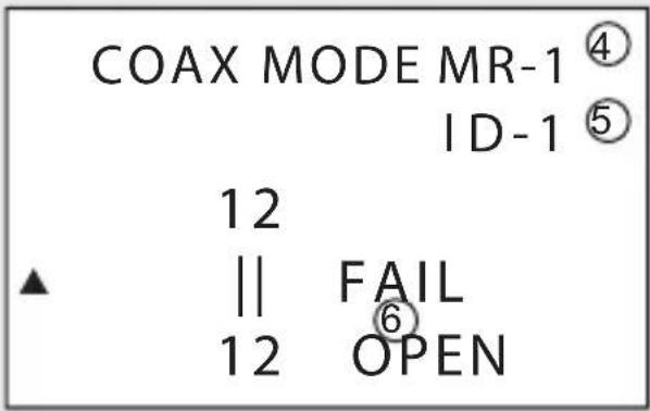
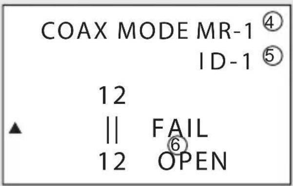
Review the following display overview for coaxial cable test mode before beginning testing:
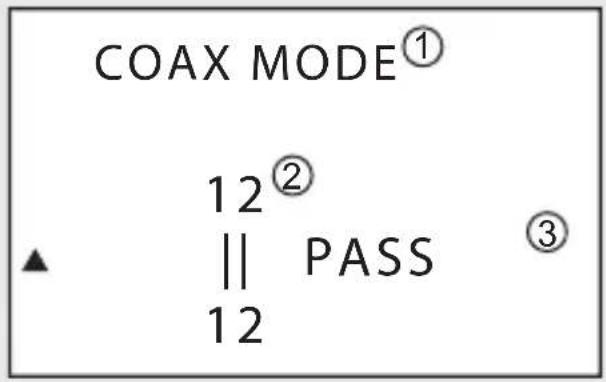

III. 3
1 Mode, cable type
2 Conductors
3 Result: "PASS" (positive result), "FAIL" (negative result)
4 Memory slot
5 ID display for remote test port (In case of "FAIL" the display shows "ID-?")
6 In case of "FAIL" (negative) reading: "OPEN" (open circuit), "SHORT" (short-circuited)
a) Connection – Remote test port
→ It may be necessary to use the F/BNC adaptor (24) for connection.
- Connect one cable end of the coaxial cable using the F connector F (2) on the cable tester.
- Connect the other end of the coaxial cable using the F connector F (13) on the remote test port.
b) Conducting a test
- Turn on the cable tester and push the COAX button. Or select "3. COAX MODE" using the navigation buttons and confirm with the TEST button.
- Push the COAX or TEST button to begin testing. The test result can be read on the display. See III. 3.
- By negative reading "FAIL": the conductors in question blink on the display.
15. TONE MODE (LOCATE MODE)
√ ZONE mode: Locate faults in LAN, telephone and coaxial cables.
→ An additional fitting external cable detector is required (not included). Heed the user manual of your external cable detector at all costs.
→ No results can be saved in TONE mode.
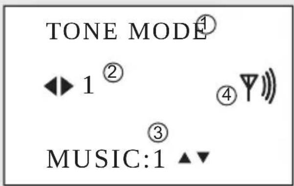
Review the following display overview for locate mode before beginning locating:
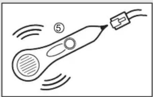
natural_image
Simple line drawing of a rocket with motion lines and a labeled section (no text or symbols)III. 4
1 Mode
2 Conductor (1 - 8) to be tested
3 Audible signal (2 signals available)
4 Audible signal control indicator
5 An additional cable detector is required for TONE mode. Contact your retailer for an appropriate model.
a) Conducting a test
- Turn on the cable tester and push the TONE button. Or select "4. TONE MODE" using the navigation buttons and confirm with the TEST button.
- Use the navigation buttons (left and right) to select the conductor (1 - 8) to be tested. Use the navigation button (up, down) to select one of the two audible signals.
- Use the cable detector to check the conductor (1 - 8) for continuity. An audible signal sounds if the test is positive.
LENGTH mode: Measure LAN and coaxial cable lengths.
Review the following display overview for length mode before beginning measuring:
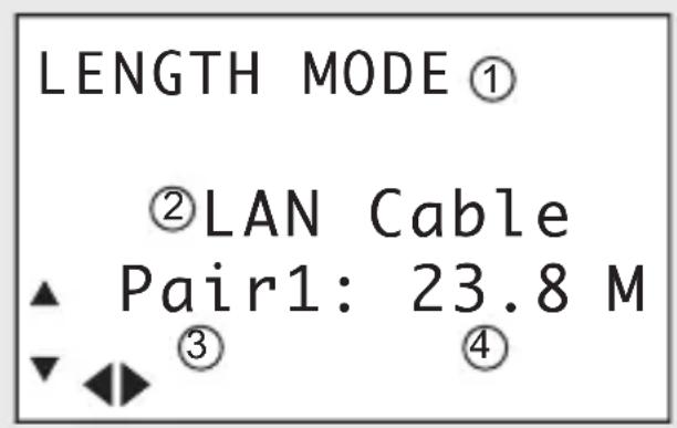
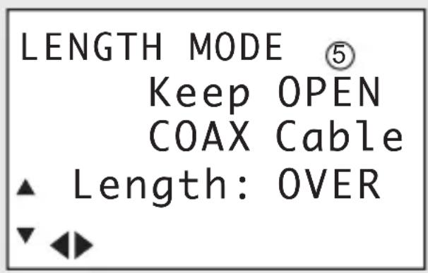
III. 5
1 Mode
2 Cable type (LAN or COAX)
3 Pair of conductors 1 - 4 (only for LAN cables)
4 Length ("OVER" is displayed for lengths > 350 m)
5 In combination with the remote test port, "Keep OPEN" is displayed
a) Connection
Connect the LAN or coaxial cable to the RJ45 jack MAIN (3) or the F connector F (2).
Also see the chapters "LAN MODE" and "COAX MODE".
Measurement is conducted with the remote test port. Disconnect the cable from the remote test port.
b) Conducting a test
- Turn on the cable tester and push the LENGTH button. Or select "5. LENGTH MODE" using the navigation buttons and confirm with the TEST button.
- Use the navigation buttons (up and down) to select the cable type ("LAN" or "COAX").
- Push the LENGTH or TEST button to begin testing. The test result can be read on the display. See Ill. 5.
- Only LAN cables: Use the navigation buttons (left and right) to display the length of a pair of conductors (1 - 4).
17. CLEANING AND CARE
- Never submerge the cable tester in water.
- Apart from occasional cleaning, the device is maintenance-free. To clean the device, use a soft, anti-static and lint-free cloth.
- Do not use any abrasive or chemical cleaners.
18. DISPOSAL
a) Product
Electronic devices are recyclable waste and must not be disposed of in the household waste.
At the end of its service life, dispose of the product according to the relevant statutory regulations.
Remove any inserted (rechargeable) batteries and dispose of them separately from the product.
b) (Rechargeable) batteries
You as the end user are required by law (Battery Ordinance) to return all used batteries/rechargeable batteries. Disposing of them in the household waste is prohibited.
Contaminated (rechargeable) batteries are labelled with this symbol to indicate that disposal in the domestic waste is forbidden. The designations for the heavy metals involved are: Cd = Cadmium, Hg = Mercury, Pb = Lead (name on (rechargeable) batteries, e.g. below the trash icon on the left).
Used (rechargeable) batteries can be returned to collection points in your municipality, our stores or wherever (rechargeable) batteries are sold.
You thus fulfil your statutory obligations and contribute to the protection of the environment.
19. TECHNICAL DATA
Power supply 9 V block battery
Connections.... RJ-45, RJ-11, F
Cable types ...... shielded, not shielded
CAT3, CAT4, CAT5, CAT5E, CAT6, CAT7, coax
Safety devices ....... Protected against overvoltage and transient ring signals
Cable test lengths....1 – 350 m, measurement with TDR
Length measurement accuracy ..... +/- 5 %
Operating conditions....0 to +50 °C, 10 – 90 % RH
Storage conditions....-10 to +60 °C, 10 – 90 % RH
Dimensions (L x W x H)....195 x 90 x 40 mm
Weight .....approx. 585 g
TABLE DES MATIÈRES
Page
ill. 1
ill. 3
natural_image
Simple line drawing of a rocket with motion lines and a labeled section (no text or symbols)ill. 4
ill. 5
Afb. 1
Afb. 3
natural_image
Simple line drawing of a rocket with motion lines and a connector (no text or symbols)Afb. 4
Afb. 5
© Copyright 2013 by Voltcraft®.

Legal notice
These operating instructions are a publication by Voltcraft®, Lindenweg 15, D-92235 Hirschau/Germany, Phone +49 96 04 / 40 87 80 (www.voltcraft.de).
All rights including translation reserved. Reproduction by any method, e.g. photocopy, microfilming, or the capture in electronic data processing systems require the prior written approval by the editor. Reprinting, also in part, is prohibited.
These operating instructions represent the technical status at the time of printing. Changes in technology and equipment reserved.
© Copyright 2013 by Voltcraft®.

Information légales
© Copyright 2013 by Voltcraft®.
- Abb. 1
- Abb. 3
- Abb. 4
- Abb. 5
- INTRODUCTION
- INTENDED USE
- CONTROLS
- Not depicted:
- SIGNS AND SYMBOLS
- SAFETY INSTRUCTIONS
- a) Persons / Product
- b) Batteries / rechargeable batteries
- c) Miscellaneous
- SCOPE OF DELIVERY
- INSERTING/REPLACING BATTERIES
- BELT CLIP
- TRIPOD HOLDER
- a) Turning on/off
- b) Navigating the menu
- c) Selecting a test mode
- d) Memory function
- Saving test / measuring readings:
- Viewing test / measuring readings:
- Deleting entries:
- e) Remote test port
- f) Adaptors/inserts
- DEVICE SETTINGS
- a) Connection – LOOPBACK
- b) Connection – Remote test port
- c) Conducting a test
- TEL MODE (TELEPHONE CABLE)
- 2
- b) Conducting a test
- a) Connection – Remote test port
- TONE MODE (LOCATE MODE)
- 4
- a) Conducting a test
- a) Connection
- CLEANING AND CARE
- DISPOSAL
- a) Product
- b) (Rechargeable) batteries
- TECHNICAL DATA
- TABLE DES MATIÈRES
- Page
- ill. 3
- ill. 5
- Afb. 1
- Afb. 3
- Afb. 4
- Afb. 5
- Legal notice
- Information légales
Brand : VOLTCRAFT
Model : CT20TDR
Category : Measuring equipment