FUH 7541 G DWK MBK - Cooker Fulgor Milano - Free user manual and instructions
Find the device manual for free FUH 7541 G DWK MBK Fulgor Milano in PDF.

User questions about FUH 7541 G DWK MBK Fulgor Milano
0 question about this device. Answer the ones you know or ask your own.
Ask a new question about this device
Download the instructions for your Cooker in PDF format for free! Find your manual FUH 7541 G DWK MBK - Fulgor Milano and take your electronic device back in hand. On this page are published all the documents necessary for the use of your device. FUH 7541 G DWK MBK by Fulgor Milano.
USER MANUAL FUH 7541 G DWK MBK Fulgor Milano
natural_image
Four black circles arranged in a 2x2 grid on white background (no text or symbols)FPH *** G ---
FPH *** G T ---
FUH *** G ---
FUH *** G T ---
FGH *** G ---
FCLH *** G ---
FCLH *** G T ---
PIANO DI COTTURA ELETTROGAS
COOKING HOB ELECTROGAS
TABLES DE CUISSON ÉLECTROGAZ
natural_image
Pure mechanical cross-section diagram without any text, numbers, or symbols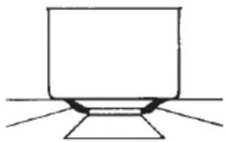
natural_image
Simple line drawing of a laptop with a stand (no text or symbols)Fig 1
corona ∅ 20-32
rapido ∅ 20-26
semirapido ∅ 14-20
ausiliario * ∅ 10-14
text_image
-1 2 L N 1 2 N L2 - GIALLO VERDE

text_image
Diagram showing two electrical circuit setups with labeled components and connections, including a battery and N-L components.Fig 6
We thank you and congratulate you on your choice.
This new carefully designed product, manufactured with the highest quality materials, has been carefully tested to satisfy all your cooking demands. We would therefore request you to read and follow these easy instructions which will allow you to obtain excellent results right from the start.
May we wish you all the very best with your modern appliance!
THE MANUFACTURER

IMPORTANT
THIS APPLIANCE IS CONCEIVED FOR DOMESTIC USE ONLY.
THE MANUFACTURER SHALL NOT IN ANY WAY BE HELD RESPONSIBLE FOR WHATEVER INJURIES OR DAMAGES ARE CAUSED BY INCORRECT INSTALLATION OR BY UNSUITABLE, WRONG OR ABSURD USE.
THIS APPLIANCE IS NOT INTENDED FOR USE BY PERSONS (INCLUDING CHILDREN) WITH REDUCED PHYSICAL, SENSORY OR MENTAL CAPABILITIES, OR LACK OF EXPERIENCE AND KNOWLEDGE, UNLESS THEY HAVE BEEN GIVEN SUPERVISION OR INSTRUCTION CONCERNING USE OF THE APPLIANCE BY A PERSON RESPONSIBLE FOR THEIR SAFETY. CHILDREN SHOULD BE SUPERVISED TO ENSURE THAT THEY DO NOT PLAY WITH THE APPLIANCE.
INDEX page
Instructions for use 2
Installation 2
Use 2
Gas burners 2
Models with Dual Wok burner 2
Knob lighting (if any) 3
Timer (if any) 3
Timer: programming of the time to turn off a burner 3
Timer: acoustic signal only 4
Keypad lock 4
Maintenance 5
Instructions for the installer 6
Installation 6
Positioning 6
Gas connection 8
Rigid/semi rigid metal connection 8
Electrical connection 8
Adaptation to various types of gas 9
User characteristics 10
Installation
All the operations concerned with the installation (electrical and gas connections, adaptation to type of gas, necessary adjustments, etc.) must be carried out by qualified technicians, in terms with the standards in force.
For specific instructions, kindly read the part reserved for the installation technician.
Use
Gas burners (Fig. 1)
The ignition of the gas burner is carried out by putting a small flame to the upper part holes of the burner, pressing and rotating the corresponding knob in an anti-clockwise manner, until the maximum position has coincided with the marker. When the gas burner has been turned on, adjust the flame according to need. The minimum position is found at the end of the anti-clockwise rotation direction.
For models with automatic/ simultaneous (with one hand) ignition, it is sufficient to proceed as described above using the corresponding knob. The electric spark between the ignition plug and the burner provides the ignition of the burner itself. After ignition, immediately release the push-button and adjust the flame according to need.
For models with a thermoelectric safety system, the burner is ignited as in the various cases described above, keeping the knob fully pressed on the maximum position for approximately 3/5 seconds. After releasing the knob, make sure the burner is actually lit.
NB: we recommend the use of pots and pans with a diameter matching that of the burner, thus preventing the flame from escaping from the bottom part and surrounding the pot
- do not leave any empty pots or pans on the fire
When cooking is finished, it is also a good norm to close the main gas pipe tap and/or cylinder.
GAS
natural_image
Pure mechanical cross-section diagram without any text, numbers, or symbols
natural_image
Simple line drawing of a laptop with a stand (no text or symbols)Fig 1
wok ∅ 20-32
fast ∅ 20-26
semifast ∅ 14-20
auxiliary* ∅ 10-14
*with reduction grid
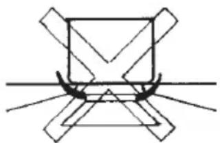
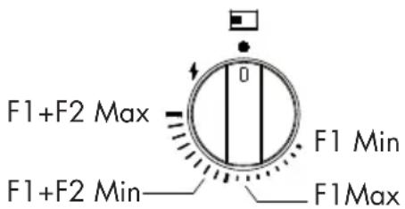
Models with Dual Wok burner (Fig.2)
Some models are equipped with a Dual Wok burner. It is possible to light the central and external flame (F1+F2) by turning and pressing the knob anti-clockwise or to light the central burner (F1) only, as shown in the figure below.
text_image
F1+F2 Max F1 Min F1+F2 Min F1Max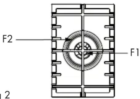
text_image
F2 F1 2Fig 2

IMPORTANT
- use of the appliance produces heat and moisture in the room where it is installed. Make sure the kitchen is sufficiently ventilated; keep natural ventilation holes open or install mechanical ventilation devices (such as a hood).
- Prolonged use of the appliance may require additional ventilation, such as opening a window.

GAS PROTEKT
- on floors with thermoelectric protection do not keep the ignite button pushed for more than 15 seconds. If the burner has not ignited after 15 seconds, open the door of the room and wait at least one minute before making a further attempt.
Knob lighting (if any)
When a knob is turned away from the OFF position, it will light up (white).
When a burner is in use and is then turned off, the knob lights up red, giving the "hot burner" warning. The light goes out after the burner has had time to cool down.
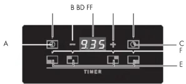
Timer (if any) (fig.3)
3 Functions:
• TIMER - programmed switch off
- TIMER - acoustic signal
- KEYPAD LOCK
text_image
B BD FF A - 9.35 + C F E TIMERFig 3
A = ON/OFF button
B = Increase / Decrease keys
C = Timer Button
D = Display
E = Cooking zones selection keys
F = Indication LED: Flashing (Associated with the display) / Fixed (active)
TIMER: Programming of the time to switch off a burner
With the device it is possible to set independently for each of the burners a time after which the burner switches off automatically.

ATTENTION
Turning the knob to the OFF position will always turn off the corresponding burner, even if the timed function is active.
Programming
Press the ON/OFF button. In the upper part of the button the LED indicating activation will light up.
In the control panel, where the zones of each burner are represented, press the button corresponding to the zone for which the automatic switch-off is to be set; the burner indicator (LED) will start to flash to signal that the burner is currently ready for programming while the timer display will show 0.00.
With the + / - keys it is possible to set the time, with 30-second steps from 1 to 10 minutes and with 1-minute steps from 11 up to a maximum of 240 minutes.
The selected burner is identified by the corresponding LED indicator in flashing mode. To select the desired area, with displaying of the relative time on the display, press the corresponding button.
Cancellation
During the time programming it is possible to reset the current setting at any time by pressing for 5 seconds the button corresponding to the burner which is to be reset, (a time equal to zero deactivates the burner timer).
It will also be possible to simultaneousness reset all the timings by pressing the ON/OFF button for 5 seconds.
TIMER: Acoustic signal only
With the device it is also possible to set the timer function; this function has no influence on the operation of the burners.
Programming
Press the ON/OFF button. In the upper part of the button the LED indicating activation will light up.
Press the timer button. The indicator (LED) will start to flash to indicate that it is currently ready for programming and the display will show 0.00.
With the + / - keys it is possible to set the time, with 30-second steps from 1 to 10 minutes and with 1-minute steps from 11 up to a maximum of 240 minutes.
If the timer is selected, it is identified by the relative LED indicator in flashing mode. To display the time on the display, press the timer button.
Cancellation
During operation it is possible at any time to reset the current setting by pressing the timer button for 5 seconds (a time equal to zero deactivates the function).
Keypad lock
Once a timer auto-off or timer function is set, the keypad can be locked by pressing only once the ON/OFF button. The previously entered settings will be retained and it will not be possible to change them until the ON/OFF button is re-enabled.
Prior to any operation, disconnect the appliance from the electrical system.
For long-life to the equipment, a general cleaning operation must take place periodically, bearing in mind the following:
- the glass, steel and/or enamelled parts must be cleaned with suitable non-abrasive or corrosive products (found on the market). Avoid chlorinebase products (bleach, etc.);
- avoid leaving acid or alkaline substances on the working area (vinegar, salt, lemon juice, etc.).
- the wall baffle and the small covers (mobile parts of the burner) must be washed frequently with boiling water and detergent, taking care to remove every possible encrustation. Dry carefully and check that none of the burner holes is fully or partially clogged;
NB: Cleaning of the taps must be carried out by qualified personnel, who must be consulted in case of any functioning anomaly.
Check periodically the state of conservation of the flexible gas feed pipe. In case of leakage, call immediately the qualified technicians for its replacement.
DO NOT USE STEAM CLEANERS
EN Instructions for the installer
Installation
This appliance is not provided with a combustion product discharge. It is recommended that it be installed in sufficiently aerated places, in terms of the laws in force. The quantity of air which is necessary for combustion must not be below 2.0 m^3/h for each kW of installed power. See table of burner power.
Note: the device is in installation class 3. The appliance's adjustment parameters are shown on the plate attached to its housing.
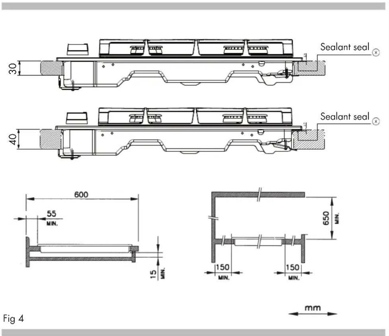
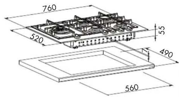
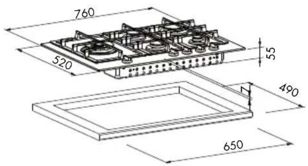
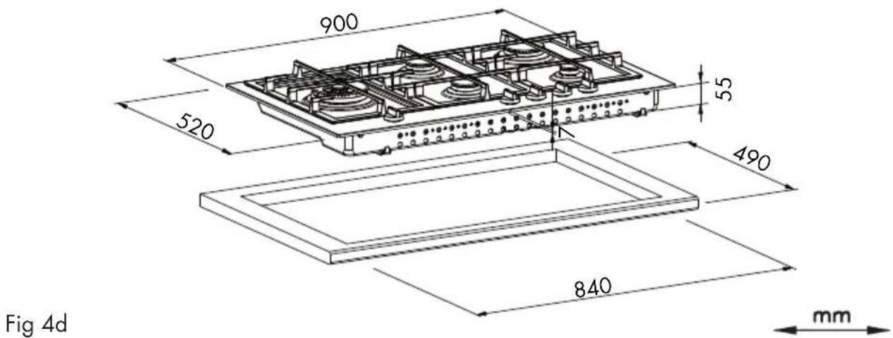
Positioning
(Fig. 4). The appliance can be fitted into a working area as illustrated on the corresponding figure. Before positioning the hob, fit the seal ✗ around the entire periphery of the hole cut in the worktop.
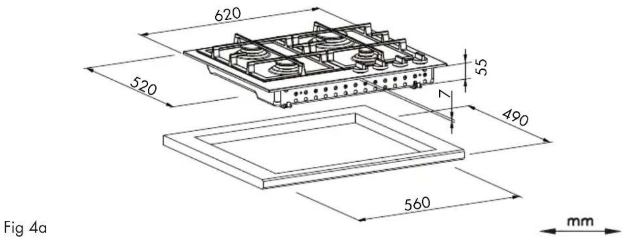
MOD: 60 CM STAINLESS STEEL / GLASS / GLASS-CERAMIC
text_image
Fig 4a 620 520 55 7 490 560 mmMOD: 75 CM STAINLESS STEEL MOD: 75 CM GLASS / GLASS-CERAMIC
text_image
760 520 55 490 560Fig 4b
text_image
760 520 55 490 650Fig 4c

MOD: 90 CM STAINLESS STEEL / GLASS / GLASS-CERAMIC
text_image
900 520 55 490 840 mm Fig 4dGas connection
(Fig. 5) Connect the appliance to the gas cylinder or to the installation according to the prescribed standards in force, and ensure beforehand, that the appliance matches the type of gas available.
Otherwise, see "Adaptation to various types of gas".
Furthermore, check that the feed pressure falls within the values described on the table: "User characteristics".
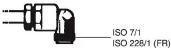
Rigid/semi rigid metal connection
Carry out the connection with fittings and metal pipes (even flexible pipes) so as to obtain counter stress the inner parts of the appliance.
NB: when the installation has been carried out, check the perfect sealing of the entire connection system, by using a soapy solution.
text_image
ISO 7/1 ISO 228/1 (FR)Fig 5
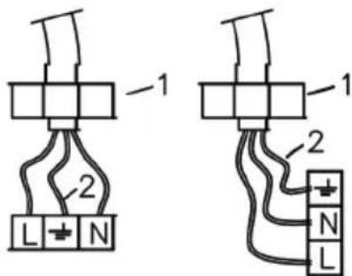
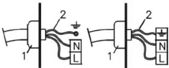
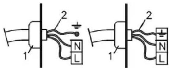
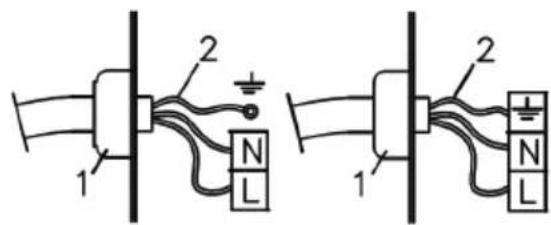
Electrical connection
(Fig. 6) Prior to carrying out the electrical connection, please ensure that:
- the plant characteristics are such as to follow what is indicated on the matrix plate placed at the bottom of the working area;
- that the plant is fitted with an efficient earth connection, following the standards and law provisions in force. The earth connection is compulsory in terms of the law.
Should there be no cable and/or plug on the equipment, use suitable absorption material for the working temperature as well, as indicated
on the matrix plate. Under no circumstance must the cable reach a temperature above 50^ C of the ambient temperature.
If connecting directly to the mains power supply, fit a multi-pole switch of a suitable size for the rated capacity with a clearance distance which completely disconnects the power line under overvoltage category III conditions, consistently with the rules of installation (the yellow/green earth wir must not be interrupted). The plug or omnipolar switch must be easily reached on the installed equipment.

IMPORTANT
To avoid all risk, if the power cable becomes damaged, it must only be replaced by the manufacturer, by an authorised service centre, or by a qualified electrician.
1 - CABLE-CLAMP
text_image
-1 2 L N 1 2 N L2 - YELLOW / GREEN
text_image
Electrical circuit diagram showing two configurations of a motor or generator with labeled components and connectionsFig 6
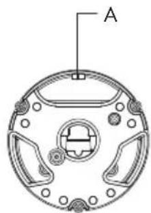
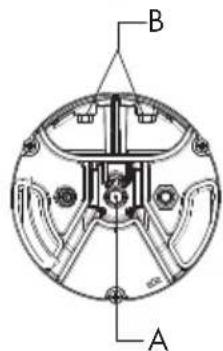
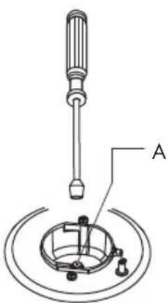
Adaptation to various types of gas
Should the appliance be reset for a different type of gas than available, proceed as follows:
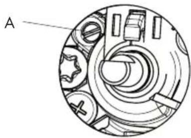
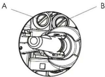
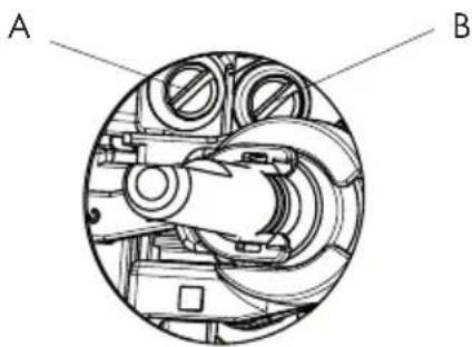
- replace the injectors (Fig. 7) with the corresponding type of gas to be used (see table "Uses characteristics")
- to adjust to the minimum, use a screwdriver on the screw placed on the tap (Fig. 8) after turning the tap to its minimum position. For LPG (butane / propane) screw tight.
WOK 2 WOK 3
natural_image
Technical diagram of a circular mechanical component with labeled point A (no text or symbols beyond label)DUAL
text_image
B ASINGLE

text_image
AFig 7
SINGLE WOK 2 WOK 3
natural_image
Technical diagram of a mechanical assembly with labeled component A (no text or symbols beyond label)DUAL

natural_image
Cross-sectional diagram of a mechanical device showing internal components (no text or symbols)Fig 8
USER CHARACTERISTICS
| GAS BURNERS | |||||||
| POWER SUPPLY PRESSURE TYPE mbar NORM. | BURNER | ∅ INJECTOR 1/100 mm | NOMINAL HEAT OUTPUT | CONSUMPTION | |||
| Natural gas G20 20 | rapid 129 300 | 0 W 286 | l/h | ||||
| semi-rapid 101 | 1750 W 167 | ||||||
| auxiliary 77 1 | 000 W 95 | ||||||
| wok 3 141 35 | 000 W 333 | ||||||
| wok 3 150 40 | 000 W 381 | ||||||
| wok 2 137 35 | 000 W 333 | ||||||
| wok 2 145 40 | 000 W 381 | ||||||
| dual | 2x95 | 4000 W 381 | |||||
| 71 | |||||||
| Liquid gas G30/G31 28-30/37 | rapid 87 300 | 0 W 218 | g/h | ||||
| semi-rapid 66 | 1750 W 127 | ||||||
| auxiliary 50 1 | 000 W 73 | ||||||
| wok 3 94 35 | 000 W 254 | ||||||
| wok 3 102 40 | 000 W 291 | ||||||
| wok 2 94 35 | 000 W 254 | ||||||
| wok 2 101 40 | 000 W 291 | ||||||
| dual | 2x65 | 4000 W 291 | |||||
| 46 | |||||||
| Natural gas G25.3 | 25 | rapid 130 30 | 00 W 325 | l/h | |||
| semi-rapid 100 | 1750 W 190 | ||||||
| auxiliary 78 1 | 000 W 108 | ||||||
| wok 3 130 35 | 000 W 380 | ||||||
| wok 3 150 40 | 000 W 434 | ||||||
| wok 2 137 35 | 000 W 380 | ||||||
| wok 2 147 40 | 000 W 434 | ||||||
| dual | 2x98 | 4000 W 434 | |||||
| 71 | |||||||
| Town gas G110 8 | rapid 320 30 | 00 W 681 | l/h | ||||
| semi-rapid 192 | 1750 W 397 | ||||||
| auxiliary | 150 100 | 0 W 227 | |||||
| wok 3 350 35 | 00 W 794 | ||||||
| wok 3 350 40 | 00 W 907 | ||||||
| wok 2 350 35 | 00 W 794 | ||||||
| wok 2 350 40 | 00 W 907 | ||||||
| dual | 2x250 | 4000 W 907 | |||||
| 130 | |||||||
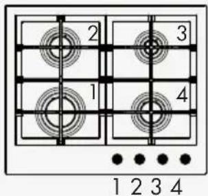
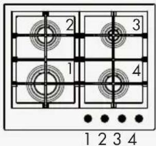
Mod: 60 cm
Standard with Timer
text_image
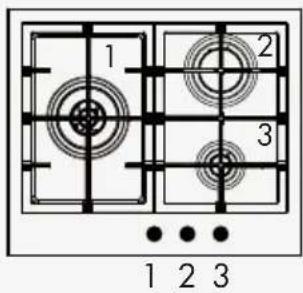
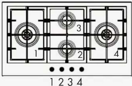
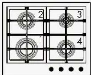
1 2 3 1 2 3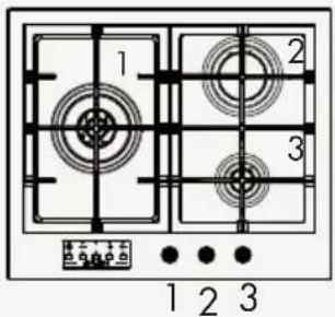
text_image
1 2 3 1 2 31: W3 / W2 / Dual
2: Rapid
3: Auxiliary
text_image
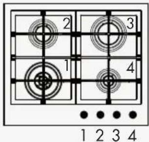
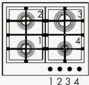
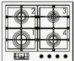
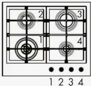
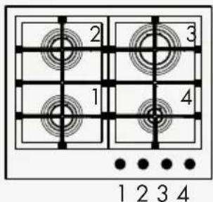
2 3 1 4 1 2 3 4
text_image
2 3 1 4 1 2 3 41: W3 / W2 / Dual
2: Semi-rapid
3: Rapid
4: Auxiliary
text_image
2 3 1 4 1 2 3 4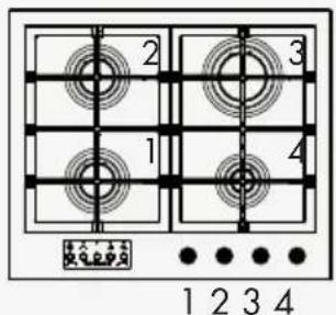
text_image
2 3 1 4 1 2 3 41: Semi-rapid
2: Semi-rapid
3: Rapid
4: Auxiliary
text_image
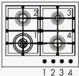
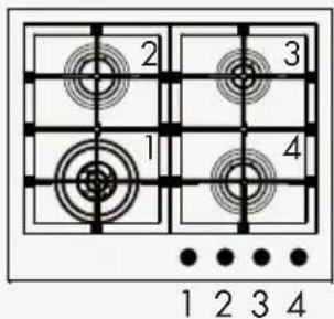
2 3 1 4 1 2 3 4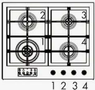
text_image
2 3 1 4 1 2 3 41: W3 / W2 / Dual
2: Semi-rapid
3: Auxiliary
4: Semi-rapid
text_image
2 3 1 4 1 2 3 4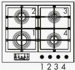
text_image
2 3 1 4 1 2 3 41: Rapid
2: Semi-rapid
3: Auxiliary
4: Semi-rapid
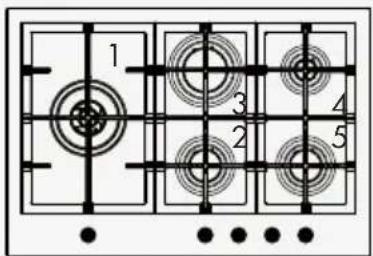
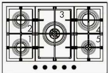
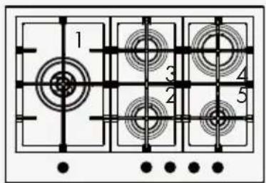
Mod: 75 cm
Standard with Timer

text_image
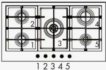
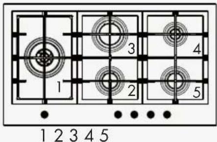
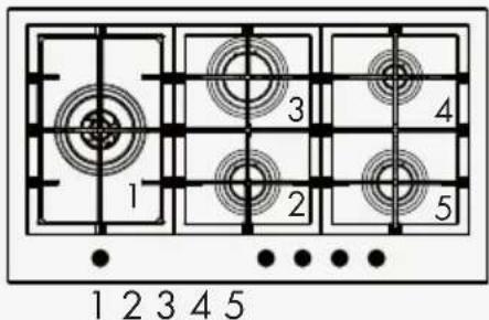
1 2 3 4 51 2 3 4 5
1: Semi-rapid
2: Semi-rapid
3: W3 / W2 / Dual
4: Rapid
5: Auxiliary

text_image
1 3 4 2 51 2 3 4 5

text_image
1 3 4 2 51 2 3 4 5
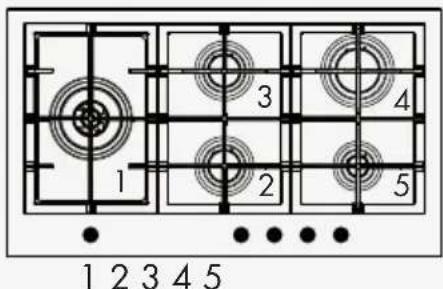
1: W3 / W2 / Dual
2: Semi-rapid
3. Semi-rapid
4: Rapid
5: Auxiliary
text_image
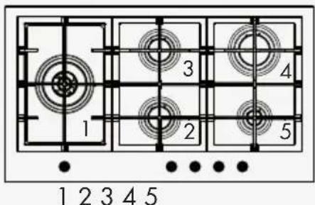
1 3 4 2 512345

text_image
1 3 4 2 51 2 3 4 5
1: W3 / W2 / Dual
2: Semi-rapid
3. Rapid
4: Auxiliary
5: Semi-rapid
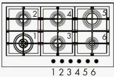
Mod: 90 cm
Standard with Timer
text_image
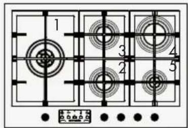
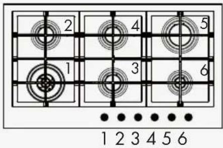
2 4 5 1 3 6 1 2 3 4 5 61: W3 / W2 / Dual
2: Semi-rapid
3: Semi-rapid
4: Semi-rapid
5: Rapid
6: Auxiliary
text_image
1 2 3 4 5 1 2 3 4 5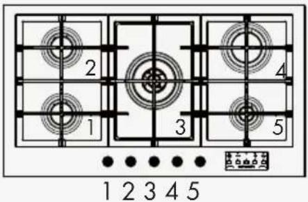
text_image
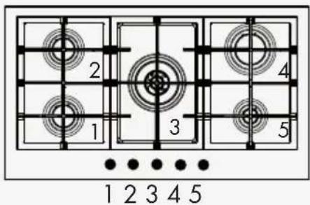
2 4 1 3 5 1 2 3 4 51: Semi-rapid
2: Semi-rapid
3. W3 / W2 / Dual
4: Rapid
5: Auxiliary
text_image
1 2 3 4 5 1 2 3 4 5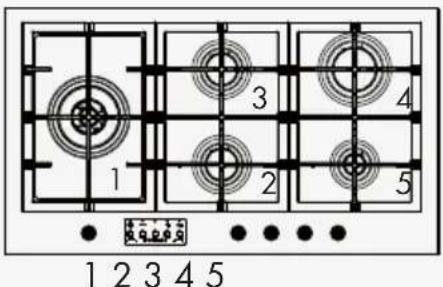
text_image
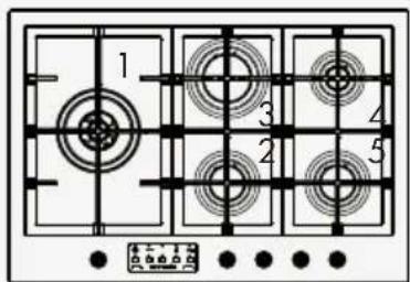
1 2 3 4 51: W3 / W2 / Dual
2: Semi-rapid
3. Semi-rapid
4: Rapid
5: Auxiliary
text_image
1 2 3 4 1 2 3 4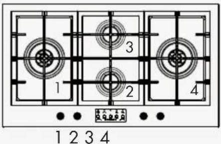
text_image
1 2 3 41: W3 / W2 / Dual
2: Semi-rapid
3. Semi-rapid
4: W3 / W2 / Dual
text_image
1 2 3 4 5 1 2 3 4 5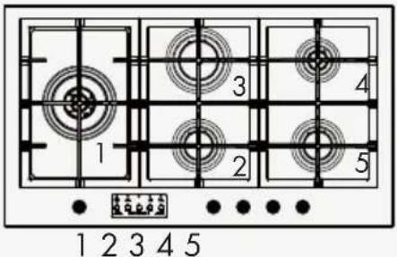
text_image
1 2 3 4 5 1 2 3 4 51: W3 / W2 / Dual
2: Semi-rapid
3. Rapid
4: Auxiliary
5: Semi-rapid
Cher client,
natural_image
Pure mechanical cross-section diagram without any text, numbers, or symbols
natural_image
Simple line drawing of a laptop with a stand (no text or symbols)Fig 1
wok ∅ 20-32
rapide ∅ 20-26
semirapide ∅ 14-20
auxiliaire* ∅ 10-14
text_image
-1 2 L N 1 2 N L2 - JAUNE ET VERT
text_image
Diagram showing two electrical circuit setups with labeled components and connections, including a battery and N-L components.Fig 6
text_image
2 3 1 4 ● ● ● ●1 2 3 4
1: C3 / C2 / Dual
2: Semi-rapide
3: Auxiliaire
4: Semi-rapide
text_image
1 2 3 41234
text_image
2 3 1 41234
1: Rapide
2: Semi-rapide
3: Auxiliaire
4: Semi-rapide
Mod: 75 cm
Gas burners (Abb. 1)
natural_image
Pure mechanical cross-section diagram without any text, numbers, or symbols
natural_image
Simple line drawing of a computer monitor with base and stand (no text or symbols)Abb. 1
wok ∅ 20-32
schnell ∅ 20-26
halbschnell ∅ 14-20
text_image
-1 2 L N 1 2 N Ltext_image
Diagram showing two electrical circuit setups with labeled components and connections, including N and L poles.Abb. 6
natural_image
Technical diagram of a circular mechanical component with labeled point A (no text or symbols beyond label)DUAL

text_image
B ASINGLE
text_image
AAbb. 7
SINGLE WOK 2 WOK 3

natural_image
Cross-sectional diagram of a mechanical assembly with labeled component A (no text or symbols beyond label)DUAL
natural_image
Cross-sectional diagram of a mechanical device showing internal components (no text or symbols)Abb. 8
natural_image
Pure mechanical cross-section diagram without any text, numbers, or symbols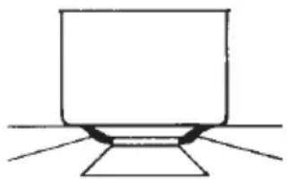
natural_image
Simple line drawing of a laptop with a screen and stand (no text or symbols)Fig 1
corona ∅ 20-32
rápido ∅ 20-26
semirápido ∅ 14-20
auxiliar* ∅ 10-14
text_image
-1 2 L N 1 2 N L2 - AMARILLO VERDE
text_image
Diagram showing two electrical circuit setups with labeled components and connections, including a battery and coils.Fig 6
natural_image
Pure mechanical cross-section diagram without any text, numbers, or symbols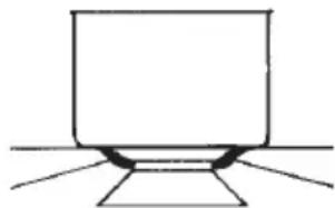
natural_image
Simple line drawing of a laptop with stand (no text or symbols)Afb. 1
wok ∅ 20-32
snel ∅ 20-26
matig snel ∅ 14-20
sudderpit* ∅ 10-14
text_image
-1 2 L N 1 2 N L2 - DE GEEL/GROENE

text_image
Diagram showing two electrical circuit setups with labeled components and connections, including a battery and coils.Afb. 6
natural_image
Technical diagram of a mechanical assembly with labeled component A (no text or symbols beyond label)DUAL
natural_image
Cross-sectional diagram of a mechanical device showing internal components (no text or symbols)Afb. 8
KENMERKEN GEBRUIKERS
| GASBRANDERS | |||||||
| VOEDING TYPE DRUK mbar NORM. | BRANDER | ∅ SPROEIER 1/100 mm | NOMINAAL THERMISCH VERMOGEN | VERBRUIK | |||
| Aardgas G20 20 | snel 129 3000 | W 286 | l/h | ||||
| semisnel 101 | 1750 W 167 | ||||||
| hulp 77 1000 | W 95 | ||||||
| kroon 3 141 | 3500 W 333 | ||||||
| kroon 3 150 | 4000 W 381 | ||||||
| kroon 2 137 | 3500 W 333 | ||||||
| kroon 2 145 | 4000 W 381 | ||||||
| dual | 2x95 | 4000 W 381 | |||||
| 71 | |||||||
| LPG G30/G31 28-30/ | 37 | snel 87 3000 | W 218 | g/h | |||
| semisnel 66 1 | 750 W 127 | ||||||
| hulp 50 1000 | W 73 | ||||||
| kroon 3 94 3 | 500 W 254 | ||||||
| kroon 3 102 | 4000 W 291 | ||||||
| kroon 2 94 3 | 500 W 254 | ||||||
| kroon 2 101 | 4000 W 291 | ||||||
| dual | 2x65 | 4000 W 291 | |||||
| 46 | |||||||
| Aardgas G25.3 25 | snel 130 3000 | W 325 | l/h | ||||
| semisnel 100 | 1750 W 190 | ||||||
| hulp 78 1000 | W 108 | ||||||
| kroon 3 130 | 3500 W 380 | ||||||
| kroon 3 150 | 4000 W 434 | ||||||
| kroon 2 137 | 3500 W 380 | ||||||
| kroon 2 147 | 4000 W 434 | ||||||
| dual | 2x98 | 4000 W 434 | |||||
| 71 | |||||||
| stadsgas | G110 8 | snel 320 3000 | W 681 | l/h | |||
| semisnel 192 | 1750 W 397 | ||||||
| hulp | 150 1000 | W 227 | |||||
| kroon 3 350 | 3500 W 794 | ||||||
| kroon 3 350 | 4000 W 907 | ||||||
| kroon 2 350 | 3500 W 794 | ||||||
| kroon 2 350 | 4000 W 907 | ||||||
| dual | 2x250 | 4000 W 907 | |||||
| 130 | |||||||
Mod: 60 cm
Standaard met Timer

text_image
1 2 3 1 2 3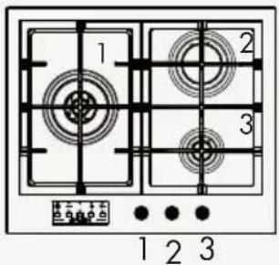
text_image
1 2 3 1 2 31: K3 / K2 / Dual
2: Snel
3: Hulp
text_image
2 3 1 4 1 2 3 4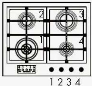
text_image
2 3 1 4 1 2 3 41: K3 / K2 / Dual
2: Semisnel
3: Snel
4: Hulp
text_image
2 3 1 4 1 2 3 4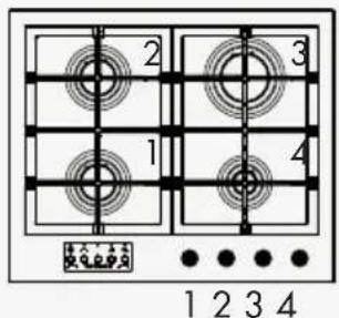
text_image
2 3 1 4 1 2 3 41: Semisnel
2: Semisnel
3: Snel
4: Hulp
text_image
2 3 1 4 1 2 3 4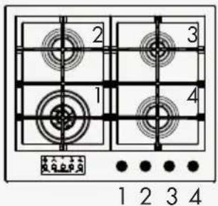
text_image
2 3 1 4 ●●●● 1 2 3 41: K3 / K2 / Dual
2: Semisnel
3: Hulp
4: Semisnel
text_image
2 3 1 4 1 2 3 4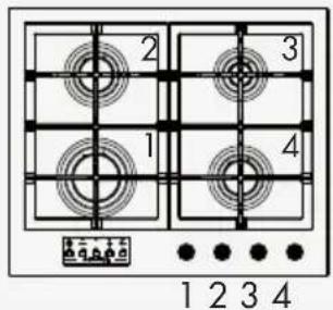
text_image
2 3 1 4 1 2 3 41: Snel
2: Semisnel
3: Hulp
4: Semisnel
Mod: 75 cm
Standaard met Timer
text_image
1 2 3 4 51 2 3 4 5
1: Semisnel
2: Semisnel
3: K3 / K2 / Dual
4: Snel
5: Hulp
text_image
1 3 4 2 51 2 3 4 5
text_image
1 3 4 2 51 2 3 4 5
1: K3 / K2 / Dual
2: Semisnel
3. Semisnel
4: Snel
5: Hulp

text_image
1 3 4 2 512345
text_image
1 3 4 2 51 2 3 4 5
1: K3 / K2 / Dual
2: Semisnel
3. Snel
4: Hulp
5: Semisnel
Mod: 90 cm
Standaard met Timer
text_image
2 4 5 1 3 6 1 2 3 4 5 61: K3 / K2 / Dual
2: Semisnel
3: Semisnel
4: Semisnel
5: Snel
6: Hulp
text_image
1 2 3 4 5 1 2 3 4 5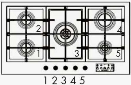
text_image
2 1 3 4 5 1 2 3 4 51: Semisnel
2: Semisnel
- K3 / K2 / Dual
4: Snel
5: Hulp
text_image
1 2 3 4 5 1 2 3 4 5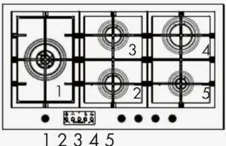
text_image
1 2 3 4 51: K3 / K2 / Dual
2: Semisnel
- Semisnel
4: Snel
5: Hulp

text_image
1 2 3 4 1 2 3 4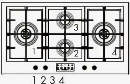
text_image
1 2 3 41: K3 / K2 / Dual
2: Semisnel
- Semisnel
4: K3 / K2 / Dual
text_image
1 2 3 4 5 1 2 3 4 5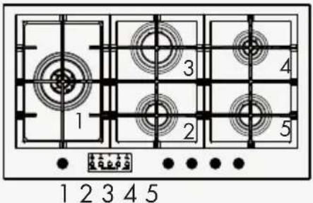
text_image
1 2 3 4 5 1 2 3 4 51: K3 / K2 / Dual
2: Semisnel
- Snel
4: Hulp
5: Semisnel
Ex.mo. Sr. Cliente,
natural_image
Pure mechanical cross-section diagram without any text, numbers, or symbols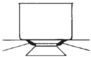
natural_image
Simple line drawing of a computer monitor with base and stand (no text or symbols)Fig 1
coroa ∅ 20-32
rápido ∅ 20-26
semi-rápido ∅ 14-20
auxiliar* ∅ 10-14
text_image
-1 2 L ⊕ N 1 2 N L2 - AMARELO VERDE

text_image
Diagram showing two electrical circuit setups with labeled components and connections, including a battery and N-L elements.Fig 6