Rugid - Motorcycle DANFOSS - Free user manual and instructions
Find the device manual for free Rugid DANFOSS in PDF.

User questions about Rugid DANFOSS
0 question about this device. Answer the ones you know or ask your own.
Ask a new question about this device
Download the instructions for your Motorcycle in PDF format for free! Find your manual Rugid - DANFOSS and take your electronic device back in hand. On this page are published all the documents necessary for the use of your device. Rugid by DANFOSS.
USER MANUAL Rugid DANFOSS
Technical Information
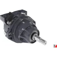
natural_image
3D rendered mechanical component with internal shaft and mounting holes (no text or symbols visible)TABLE OF CONTENTS
SERIES 26 PUMPS
Features 3
General specifications and performance data 4
Performance data charts 5
Standard catalog assemblies - dimensions 9
Order numbers 10
Optional configurations 13
Component parts - dimensions 14
Model code - single 17
Model code - multiple 19
Side-load applications 22
Load sensing priority valve 24
SERIES 26 MOTORS
General specifications 25
Performance data 26
Model code - single 28
SERIES L2 PUMPS
General specifications and performance data 30
Performance data charts 31
Standard catalog assemblies - dimensions 33
Order numbers 34
Optional configurations 36
Component parts - dimensions 37
Model code - single 40
Model code - multiple 42
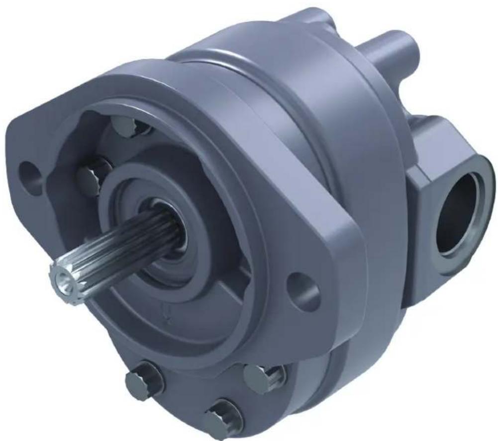
Pressures to 3500 PSI and flow to 24.1 GPM

Quiet operation
- The 13-tooth gears, versus 10 teeth in previous pumps, minimizes the flow ripple. This reduces noise as well as vibration.
- The improved trap reliefs not only increase power, they also help keep oil flowing smoothly to reduce noise.
Improved efficiency
- Improved bearing lubrication system uses inlet oil instead of high pressure oil, improving volumetric efficiency for more power output.
- The highly polished shaft and gears improve mechanical efficiency and reduce wear on these components, adding to the service life and reliability of the pump.
- The optimized trapped oil relief areas help reduce pressure ripple for quieter operation. This also decreases the input power requirements.
Field reversible
The innovative new wea plate permits simple field reversibility of the pump direction. Simply open the pump, switch the drive gear and idler gear, reposition the plug and reassemble. No extra parts are needed.
Interchangeability
The Series 26 Gear Pump has been designed to retrofit equipment using the B1 and B2 Gear Pumps. Extra shafts, porting, and mounting configurations, as well as 13 available displacements, give you the choices you need for an easy conversion to this superior pump.
Series 26 pump
General specifications and performance data
| Rotation | Field reversible |
| Mounting flange SAE A 2 Bolt | |
| Max. Continuous pressure† | 210 bar [3000 PSI]* |
| Max. Intermittent pressure†† | 240 bar [3500 PSI]** |
| Minimum speed at continuous pressure | 750 RPM |
| Maximum rotating torque at 0 pressure | 4 Nm [36 lb-in] |
| Maximum continuous operating temperature | 105°C [220°F] |
| Minimum continuous oil viscosity | 5.7 cSt [45 SUS] |
| Minimum operating temperature | -29°C [-20°F] |
| Maximum inlet vacuum at operating condition | 0,8 bar Abs. [11.6 psi Abs.] |
† Continuous - pump may be run continuously at these ratings. †† Intermittent - intermittent operation, 10% of every minute.
* 30 .6 cm³/rev . [1.87 in³/rev.] displacement max. continuous pressure is 190 bar [2750 PSI] .
** 30 .6 cm³/rev . [1.87 in³/rev.] displacement max. intermittent pressure is 224 bar [3250 PSI] .
For side load limits consult your Danfoss representativ.e.
| Displacement cm^3/r [ in^3/r ] | 6,6[.40] | 8,2[.50] | 9,5[.58] | 10,8[.66] | 13,8[.84] | 16,7[1.02] | 19,7[1.20] |
| Max. Intermittent pressure bar [PSI] | 241[3500] | 241[3500] | 241[3500] | 241[3500] | 241[3500] | 241[3500] | 241[3500] |
| Rated speed (RPM) | 3600 3600 | 3600 3600 | 3600 3600 | 3600 3200 | |||
| Minimum output flow at 207 bar [3000 PSI] and rated speed LPM [GPM] | 20,1[5.3] | 25,0[6.6] | 29,5[7.8] | 33,7[8.9] | 43,5[11.5] | 55,3[14.6] | 57,9[15.3] |
| Input power at 207 bar [3000 PSI] and rated speed and cont. Pressure kW [HP] | 9,7[13.0] | 11,9[15.9] | 14,1[18.9] | 15,5[20.8] | 20,0[26.8] | 22,0[29,4] | 26,2[35.2] |
| Displacement cm^3/r [ in^3/r ] | 22,5[1.37] | 24,3[1.48] | 25,2[1.54] | 27,7[1.69] | 29,0[1.77] | 30,6[1.87] |
| Max. Intermittent pressure bar [PSI] | 241[3500] | 241[3500] | 241[3500] | 241[3500] | 234[3400] | 224[3250] |
| Rated speed (RPM) | 3000 3000 3000 3000 3000 3000 | |||||
| Minimum output flow at 207 bar [3000 PSI] and rated speed LPM [GPM] | 62,1[16.4] | 67,0[17.7] | 69,7[18.4] | 76,5[20.2] | 79,9[21.1] | 84,4[22.3] |
| Input power at 207 bar [3000 PSI] and rated speed and cont. Pressure kW [HP] | 27,3[36.6] | 30,5[40.9] | 31,0[41.6] | 33,4[44.8] | 35,4[47.4] | 37,4[50.1] |
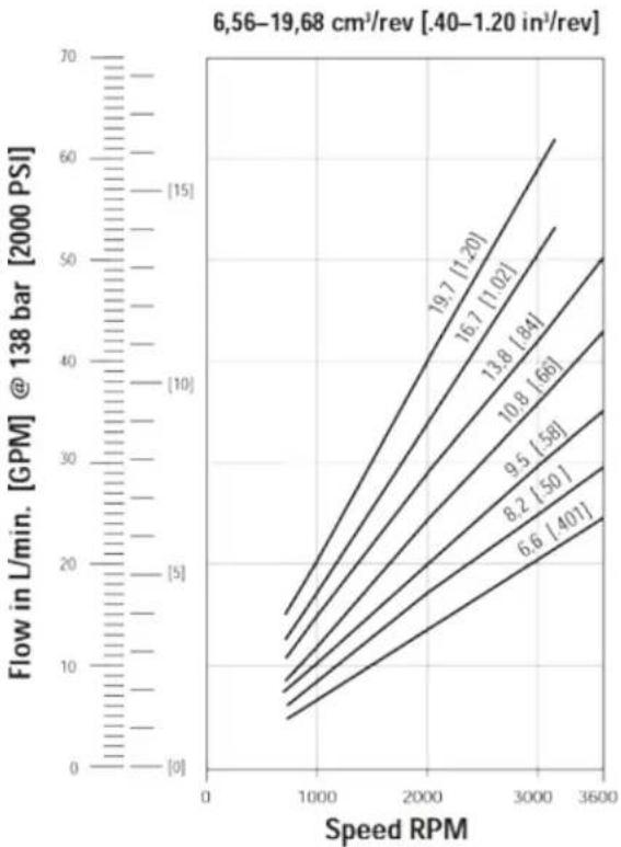
| The performance data in the table above and the following graphs was collected using a mineral base oil with a viscosity of 133-SU5 at 40°C [120°F] | ||||||
The performance data in the table above and the following graphs was collected using a mineral base oil with a viscosity of 133 SUS at 49^ [120°F]
Series 26 pump
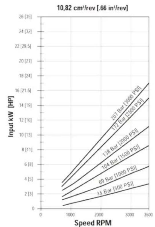
Performance data charts
line
| Speed RPM | Flow in L/min. @ 138 bar [2000 PSI] | | --------- | ---------------------------------- | | 1000 | 5 | | 2000 | 15 | | 3000 | 30 | | 3600 | 60 |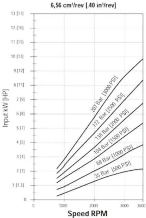
line
| Speed RPM | 35 Bar [500 PSI] | 69 Bar [1000 PSI] | 104 Bar [1500 PSI] | 138 Bar [2000 PSI] | 172 Bar [2500 PSI] | 207 Bar [3000 PSI] | | --------- | --------------- | ---------------- | ----------------- | ----------------- | ----------------- | ----------------- | | 0 | 0 | 0 | 0 | 0 | 0 | 0 | | 1000 | 1.3 | 2.0 | 3.0 | 4.0 | 5.0 | 6.0 | | 2000 | 2.0 | 3.0 | 4.5 | 6.0 | 7.5 | 9.0 | | 3000 | 2.5 | 4.0 | 6.0 | 8.0 | 10.0 | 12.0 | | 3500 | 2.5 | 4.5 | 7.0 | 9.5 | 11.5 | 13.5 |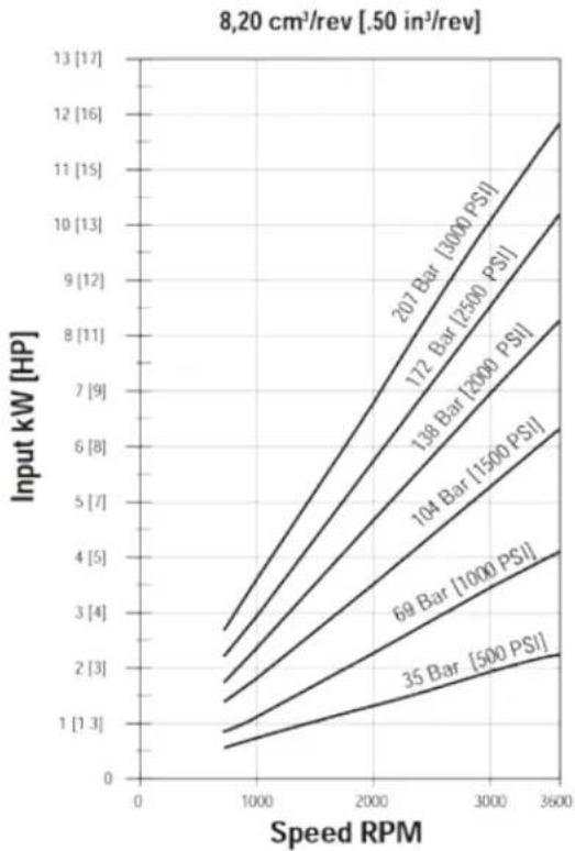
line
| Speed RPM | 35 Bar [500 PSI] | 69 Bar [1000 PSI] | 104 Bar [1500 PSI] | 138 Bar [2000 PSI] | 172 Bar [2500 PSI] | 207 Bar [5000 PSI] | | --------- | --------------- | ---------------- | ----------------- | ----------------- | ----------------- | ----------------- | | 0 | 1 | 1 | 1 | 1 | 1 | 1 | | 1000 | 1.5 | 2 | 3 | 4 | 5 | 6 | | 2000 | 2 | 3 | 4 | 5 | 6 | 7 | | 3000 | 2.5 | 4 | 5 | 6 | 7 | 8 | | 3600 | 3 | 5 | 6 | 7 | 8 | 9 |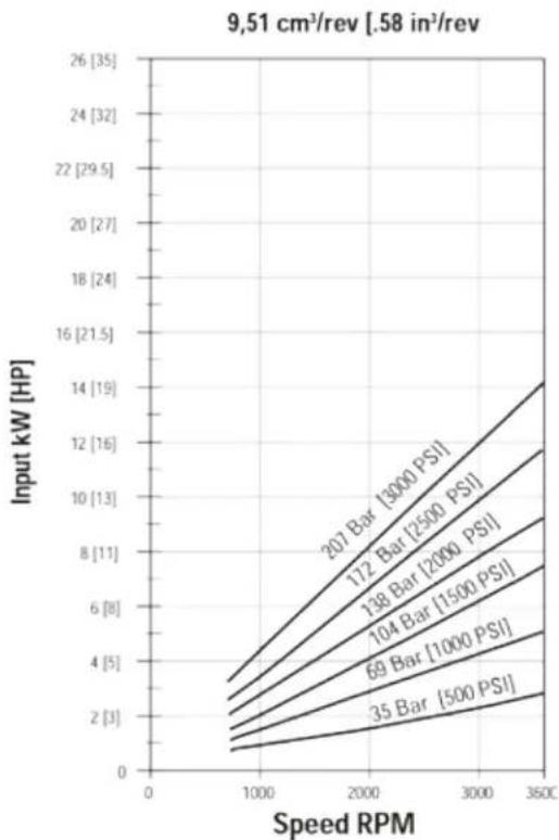
line
| Speed RPM | 35 Bar [500 PSI] | 69 Bar [1000 PSI] | 104 Bar [1500 PSI] | 138 Bar [2000 PSI] | 172 Bar [2500 PSI] | 207 Bar [3000 PSI] | | --------- | --------------- | ---------------- | ----------------- | ----------------- | ----------------- | ----------------- | | 0 | 0 | 0 | 0 | 0 | 0 | 0 | | 1000 | ~1 | ~2 | ~3 | ~4 | ~5 | ~6 | | 2000 | ~2 | ~4 | ~6 | ~8 | ~10 | ~12 | | 3000 | ~3 | ~6 | ~9 | ~12 | ~15 | ~18 | | 3500 | ~4 | ~8 | ~12 | ~16 | ~20 | ~24 |Series 26 pump
Performance data charts
line
| Speed RPM | 35 Bar [500 PSI] | 69 Bar [1000 PSI] | 104 Bar [1500 PSI] | 138 Bar [2000 PSI] | 172 Bar [2500 PSI] | 201 Bar [3000 PSI] | | --------- | ---------------- | ----------------- | ------------------ | ------------------ | ------------------ | ------------------ | | 0 | 0 | 0 | 0 | 0 | 0 | 0 | | 1000 | ~1 | ~2 | ~3 | ~4 | ~5 | ~6 | | 2000 | ~2 | ~4 | ~6 | ~8 | ~10 | ~12 | | 3000 | ~3 | ~6 | ~9 | ~12 | ~14 | ~16 | | 3500 | ~4 | ~8 | ~12 | ~16 | ~18 | ~20 |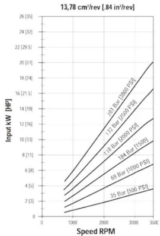
line
| Speed RPM | 35 Bar [500 PSI] | 69 Bar [1000 PSI] | 184 Bar [1500] | 138 Bar [2000 PSI] | 172 Bar [2500 PSI] | 201 Bar [3000 PSI] | | --------- | --------------- | ---------------- | -------------- | ----------------- | ------------------ | ------------------ | | 0 | 0 | 0 | 0 | 0 | 0 | 0 | | 1000 | ~1 | ~2 | ~3 | ~4 | ~5 | ~6 | | 2000 | ~2 | ~4 | ~6 | ~8 | ~10 | ~12 | | 3000 | ~3 | ~6 | ~9 | ~12 | ~14 | ~16 | | 3500 | ~4 | ~8 | ~11 | ~14 | ~16 | ~18 |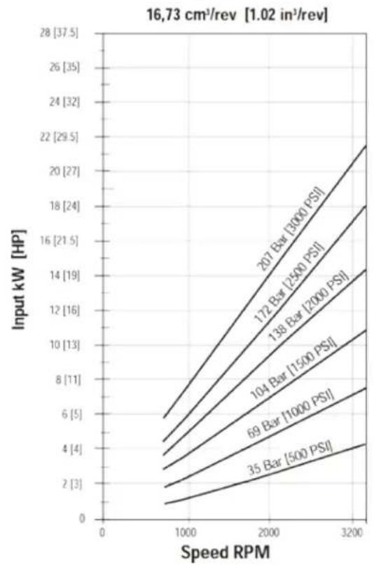
line
| Speed RPM | 35 Bar [500 PSI] | 69 Bar [1000 PSI] | 104 Bar [1500 PSI] | 138 Bar [2000 PSI] | 172 Bar [2500 PSI] | 207 Bar [3000 PSI] | | --------- | --------------- | ---------------- | ----------------- | ----------------- | ----------------- | ----------------- | | 0 | 1 | 2 | 4 | 6 | 8 | 10 | | 1000 | 2 | 4 | 6 | 8 | 10 | 12 | | 2000 | 4 | 6 | 8 | 10 | 12 | 14 | | 3200 | 6 | 8 | 10 | 12 | 14 | 16 |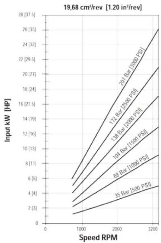
line
| Speed RPM | 35 Bar [500 PSI] | 69 Bar [1000 PSI] | 104 Bar [1500 PSI] | 138 Bar [2000 PSI] | 172 Bar [2500 PSI] | 201 Bar [3000 PSI] | | --------- | --------------- | ---------------- | ----------------- | ----------------- | ----------------- | ----------------- | | 0 | 1 | 2 | 4 | 6 | 8 | 10 | | 1000 | 2 | 4 | 6 | 8 | 10 | 12 | | 2000 | 4 | 6 | 8 | 10 | 12 | 14 | | 3200 | 6 | 8 | 10 | 12 | 14 | 16 |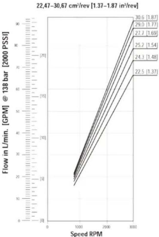
line
| Speed RPM | Flow in L/min. [GPM] @ 138 bar [2000 PSSI] | | --------- | ------------------------------------------ | | 30.6 | 90 | | 29.0 | 85 | | 27.7 | 80 | | 25.2 | 75 | | 24.3 | 70 | | 22.5 | 65 |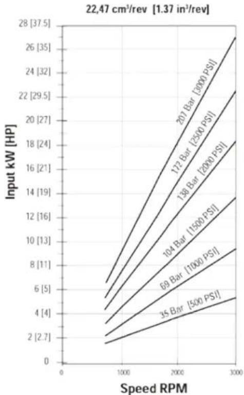
line
| Speed RPM | 35 Bar [500 PS] | 69 Bar [1000 PS] | 104 Bar [1500 PS] | 138 Bar [2000 PS] | 172 Bar [2500 PS] | 207 Bar [3000 PS] | | --------- | --------------- | ---------------- | ----------------- | ----------------- | ----------------- | ----------------- | | 0 | 2 | 4 | 6 | 8 | 10 | 12 | | 1000 | 4 | 6 | 8 | 10 | 12 | 14 | | 2000 | 6 | 8 | 10 | 12 | 14 | 16 | | 3000 | 8 | 10 | 12 | 14 | 16 | 18 |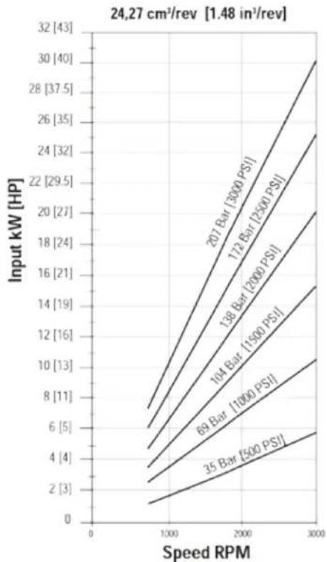
line
| Speed RPM | 35 Bar [500 PSI] | 69 Bar [1000 PSI] | 104 Bar [1500 PSI] | 138 Bar [2000 PSI] | 172 Bar [2500 PSI] | 201 Bar [3000 PSI] | | --------- | --------------- | ---------------- | ----------------- | ----------------- | ----------------- | ----------------- | | 0 | 0 | 0 | 0 | 0 | 0 | 0 | | 1000 | 2 | 4 | 6 | 8 | 10 | 12 | | 2000 | 4 | 6 | 8 | 10 | 12 | 14 | | 3000 | 6 | 8 | 10 | 12 | 14 | 16 | | 3200 | 8 | 10 | 12 | 14 | 16 | 18 |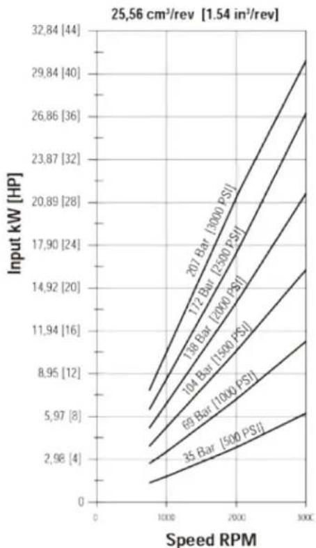
line
| Speed RPM | 35 Bar [500 PSI] | 69 Bar [1000 PSI] | 104 Bar [1500 PSI] | 118 Bar [2000 PSI] | 172 Bar [2500 PSI] | 207 Bar [3000 PSI] | | --------- | ---------------- | ----------------- | ------------------ | ------------------ | ------------------ | ------------------ | | 0 | 2.98 | 5.97 | 8.95 | 11.94 | 14.92 | 17.90 | | 1000 | ~4 | ~6.9 | ~11 | ~14.92 | ~17.90 | ~20.89 | | 2000 | ~6 | ~9 | ~14.92 | ~18.92 | ~21.87 | ~24.87 | | 3000 | ~8 | ~12 | ~18.92 | ~21.87 | ~24.87 | ~26.86 |Series 26 pump
Performance data charts
\*Multiple pump input torque limitations:
The total torque for multiple pump displacements and pressure combinations cannot exceed the maximum input torque rating of the shaft. The proper formula is pressure times displacement divided by 6.28.
![C L 25.9 [1.02] 21.1 [.83] 18 [.71] Suction port Side porting Suction port Rear porting 46.2 [1.82] 92.5 [3.64] Driveshaft centerline 18 [.71] Pressure port Rear porting Pressure port Side porting 15.0 [.59] 6.4 [.25] See shaft drawing Dia. 82.52±.030 [3.249±.001] 2X Dim A Dim B 130.0 [5.12] 106.4 [4.19] 47.6 [1.88] 83.3 [3.28] 2X Dia. 11.56±.13 [.455±.005] C L](/content/2026/04/623181/images/ede153a1e3ee48336ba96dc184e24b364ead708c3d9b743c0f9a628533ad6736.jpg)
Left hand rotation shown
Model 26001 26002 26003 26004 26005 26006 26007
| Displacement (cm3/r [in3/r]) | 6.6 [.40] | 8.2 [.50] | 9.5 [.58] | 10.8 [.66] | 13.8 [.84] | 16.7 [1.02] | 19.7 [1.20] | ||
| Dimension A (mm [in]) | 72.6 [2.86] | 74.3 [2.93] | 75.9 [2.99] | 77.5 [3.05] | 80.7 [3.18] | 83.9 [3.30] | 87.1 [3.43] | ||
| Dimension B (mm [in]) | 93.2 [3.67] | 94.9 [3.74] | 96.5 [3.80] | 98.1 [3.86] | 101.3 [3.99] | 104.5 [4.11] | 107.7 [4.24] |
| Model | 26008 | 26009 | 26010 | 26011 | 26012 | 26013 | ||
| Displacement (cm ^3 /r [in ^3 /r]) | 22.5 [1.37] | 24.3 [1.48] | 25.2 [1.54] | 27.7 [1.69] | 29.0 [1.77] | 30.6 [1.87] | ||
| Dimension A (mm [in]) | 90.3 [3.56] | 92.7 [3.65] | 93.5 [3.68] | 96.7 [3.81] | 98.6 [3.88] | 99.9 [3.93] | ||
| Dimension B (mm [in]) | 110.9 [4.37] | 113.3 [4.46] | 114.1 [4.49] | 117.3 [4.62] | 119.1 [4.69] | 120.5 [4.74] | ||
5/8 Inch 9 tooth spline
maximum input torque 62 nm [550 lb-in]
3/4 Inch 11 tooth spline
maximum input torque 119 nm [1050 lb-in]
3/4 Inch straight key
maximum input torque 113 nm [1000 lb-in]
5/8 Inch straight key
maximum input torque 56 nm [500 lb-in]
All dimensions are in mm
Series 26 pump Order numbers
| Right hand rotation product no | Left hand rotation product no | Shaft | Port location | SAE O-ring pressure port size | SAE O-ring suction port size | Replaces |
| Model 26001 - 6,6 cm3/r [.40 in ^3/r displacement | ||||||
| 26001-RZG 26001-LZG | 5/8 Keyed Side 7/8-14 | UNF-2B 1-1/16-12 | UN-2B 24300-RZA/LZA | |||
| 26001-RZH 26001-LZH | 5/8 Keyed Rear 7/8-14 | UNF-2B 1-1/16-12 | UN-2B 24300-RZC/LZD | |||
| 26001-RZJ | 26001-LZJ | 5/8 9T Spline | Side | 7/8-14 UNF-2B | 1-1/16-12 UN-2B | 24300-RZB/LZA |
| 26001-RZK | 26001-LZK | 5/8 9T Spline | Rear | 7/8-14 UNF-2B | 1-1/16-12 UN-2B | 24300-RZD/LZE |
| Model 26002 - 8,2 cm ^3/r [.50 in ^3/r displacement | ||||||
| 26002-RZA | 26002-LZA | 3/4 11T Spline | Side | 7/8-14 UNF-2B | 1-5/16-12 UN-2B | 1-5/16-12 UN-2B |
| 26002-RZB | 26002-LZB | 3/4 11T Spline | Rear | 7/8-14 UNF-2B | 1-5/16-12 UN-2B | 1-5/16-12 UN-2B |
| 26002-RZC | 26002-LZC | 3/4 Keyed | Side | 7/8-14 UNF-2B | 1-5/16-12 UN-2B | 1-5/16-12 UN-2B |
| 26002-RZD | 26002-LZD | 3/4 Keyed | Rear | 7/8-14 UNF-2B | 1-5/16-12 UN-2B | 1-5/16-12 UN-2B |
| 26002-RZE | 26002-LZE | 5/8 9T Spline | Side | 7/8-14 UNF-2B | 1-5/16-12 UN-2B | 1-5/16-12 UN-2B |
| 26002-RZF | 26002-LZF | 5/8 9T Spline | Rear | 7/8-14 UNF-2B | 1-5/16-12 UN-2B | 1-5/16-12 UN-2B |
| 26002-RZG | 26002-LZG | 5/8 Keyed | Side | 7/8-14 UNF-2B | 1-1/16-12 UN-2B | 1-1/16-12 UN-2B |
| 26002-RZH | 26002-LZH | 5/8 Keyed | Rear | 7/8-14 UNF-2B | 1-1/16-12 UN-2B | 1-1/16-12 UN-2B |
| 26002-RZJ | 26002-LZJ | 5/8 9T Spline | Side | 7/8-14 UNF-2B | 1-1/16-12 UN-2B | 1-1/16-12 UN-2B |
| 26002-RZK | 26002-LZK | 5/8 9T Spline | Rear | 7/8-14 UNF-2B | 1-1/16-12 UN-2B | 1-1/16-12 UN-2B |
| Model 26003 - 9,5 cm ^3/r [.58 in ^3/r displacement | ||||||
| 26003-RZG | 26003-LZG | 5/8 Keyed | Side | 7/8-14 UNF-2B | 1-1/16-12 UN-2B | 24302-RZB/LZB |
| 26003-RZH | 26003-LZH | 5/8 Keyed | Rear | 7/8-14 UNF-2B | 1-1/16-12 UN-2B | 24302-RZC/LZD |
| 26003-RZJ | 26003-LZJ | 5/8 9T Spline | Side | 7/8-14 UNF-2B | 1-1/16-12 UN-2B | 24302-RZA/LZA |
| 26003-RZK | 26003-LZK | 5/8 9T Spline | Rear | 7/8-14 UNF-2B | 1-1/16-12 UN-2B | 24302-RZD/LZE |
| Model 26004 - 10,8 cm3/r [.66 in3/r] displacement | ||||||
| 26004-RZA | 26004-LZA | 3/4 11T Spline | Side | 7/8-14 UNF-2B | 1-5/16-12 UN-2B | 25301-RSA/LSA |
| 26004-RZB | 26004-LZB | 3/4 11T Spline | Rear | 7/8-14 UNF-2B | 1-5/16-12 UN-2B | 25301-RSB/LSB |
| 26004-RZC | 26004-LZC | 3/4 Keyed | Side | 7/8-14 UNF-2B | 1-5/16-12 UN-2B | 25301-RSC/LSC |
| 26004-RZD | 26004-LZD | 3/4 Keyed | Rear | 7/8-14 UNF-2B | 1-5/16-12 UN-2B | 25301-RSD/LSD |
| 26004-RZE | 26004-LZE | 5/8 9T Spline | Side | 7/8-14 UNF-2B | 1-5/16-12 UN-2B | 25301-RSE/LSE |
| 26004-RZF | 26004-LZF | 5/8 9T Spline | Rear | 7/8-14 UNF-2B | 1-5/16-12 UN-2B | 25301-RSF/LSF |
| 26004-RZG | 26004-LZG | 5/8 Keyed | Side | 7/8-14 UNF-2B | 1-1/16-12 UN-2B | 24303-RZB/LZB |
| 26004-RZH | 26004-LZH | 5/8 Keyed | Rear | 7/8-14 UNF-2B | 1-1/16-12 UN-2B | 24303-RZE/LZF |
| 26004-RZJ | 26004-LZJ | 5/8 9T Spline | Side | 7/8-14 UNF-2B | 1-1/16-12 UN-2B | 24303-RZD/LZA |
| 26004-RZK | 26004-LZK | 5/8 9T Spline | Rear | 7/8-14 UNF-2B | 1-1/16-12 UN-2B | 24303-RZF/LZG |
| Model 26005 - 13,8 cm3/r [.84 in3/r] displacement | ||||||
| 26005-RZA | 26005-LZA | 3/4 11T Spline | Side | 7/8-14 UNF-2B | 1-5/16-12 UN-2B | 25302-RSA/LSA |
| 26005-RZB | 26005-LZB | 3/4 11T Spline | Rear | 7/8-14 UNF-2B | 1-5/16-12 UN-2B | 25302-RSB/LSB |
| 26005-RZC | 26005-LZC | 3/4 Keyed | Side | 7/8-14 UNF-2B | 1-5/16-12 UN-2B | 25302-RSC/LSC |
| 26005-RZD | 26005-LZD | 3/4 Keyed | Rear | 7/8-14 UNF-2B | 1-5/16-12 UN-2B | 25302-RSD/LSD |
| 26005-RZE | 26005-LZE | 5/8 9T Spline | Side | 7/8-14 UNF-2B | 1-5/16-12 UN-2B | 25302-RSE/LSE |
| 26005-RZF | 26005-LZF | 5/8 9T Spline | Rear | 7/8-14 UNF-2B | 1-5/16-12 UN-2B | 25302-RSF/LSF |
| 26005-RZG | 26005-LZG | 5/8 Keyed | Side | 7/8-14 UNF-2B | 1-1/16-12 UN-2B | 24304-RZC/LZA |
| 26005-RZH | 26005-LZH | 5/8 Keyed | Rear | 7/8-14 UNF-2B | 1-1/16-12 UN-2B | 24304-RZG/LZF |
| 26005-RZJ | 26005-LZJ | 5/8 9T Spline | Side | 7/8-14 UNF-2B | 1-1/16-12 UN-2B | 24304-RZD/LZB |
5/8 Keyed shaft has a maximum allowable input torque of 56 Nm [500 lb-in].
Series 26 pump Order numbers
| Right hand rotation product no | Left hand rotation product no | Shaft | Port location | SAE O-ring pressure port size | SAE O-ring suction port size | Replaces |
| Model 26006 - 16,7 cm3/r [1.02 in3/r] displacement | ||||||
| 26006-RZA 26006-LZA | 3/4 11T Spline | Side 7/8-14 | UNF-2B 1-5/16-12 | UN-2B 25303-RSA/LSA | ||
| 26006-RZB 26006-LZB | 3/4 11T Spline Rear | 7/8-14 | UNF-2B 1-5/16-12 | UN-2B 25303-RSB/LSB | ||
| 26006-RZC | 26006-LZC | 3/4 Keyed | Side | 7/8-14 | UNF-2B | 1-5/16-12 UN-2B |
| 26006-RZD | 26006-LZD | 3/4 Keyed | Rear | 7/8-14 | UNF-2B | 1-5/16-12 UN-2B |
| 26006-RZE | 26006-LZE | 5/8 9 T Spline | Side | 7/8-14 | UNF-2B | 1-5/16-12 UN-2B |
| 26006-RZF | 26006-LZF | 5/8 9 T Spline | Rear | 7/8-14 | UNF-2B | 1-5/16-12 UN-2B |
| 26006-RZG | 26006-LZG | 5/8 Keyed | Side | 7/8-14 | UNF-2B | 1-1/16-12 UN-2B |
| 26006-RZH | 26006-LZH | 5/8 Keyed | Rear | 7/8-14 | UNF-2B | 1-1/16-12 UN-2B |
| 26006-RZJ | 26006-LZJ | 5/8 9 T Spline | Side | 7/8-14 | UNF-2B | 1-1/16-12 UN-2B |
| 26006-RZK 26006-LZK | 5/8 9 T Spline Rear | 7/8-14 | UNF-2B 1-1/16-12 | UN-2B 24305-RZH/LZG | ||
| Model 26007 - 19,7 cm3/r [1.20 in3/r] Displacement | ||||||
| 26007-RZA 26007-LZA | 3/4 11T Spline | Side 7/8-14 | UNF-2B 1-5/16-12 | UN-2B 25304-RSA/LSA | ||
| 26007-RZB | 26007-LZB | 3/4 11T Spline | Rear | 7/8-14 | UNF-2B | 1-5/16-12 UN-2B |
| 26007-RZC | 26007-LZC | 3/4 Keyed | Side | 7/8-14 | UNF-2B | 1-5/16-12 UN-2B |
| 26007-RZD | 26007-LZD | 3/4 Keyed | Rear | 7/8-14 | UNF-2B | 1-5/16-12 UN-2B |
| 26007-RZE | 26007-LZE | *5/8 9 T Spline | Side | 7/8-14 | UNF-2B | 1-5/16-12 UN-2B |
| 26007-RZF | 26007-LZF | *5/8 9 T Spline | Rear | 7/8-14 | UNF-2B | 1-5/16-12 UN-2B |
| 26007-RZG | 26007-LZG | **5/8 Keyed | Side | 7/8-14 | UNF-2B | 1-1/16-12 UN-2B |
| 26007-RZH | 26007-LZH | **5/8 Keyed | Rear | 7/8-14 | UNF-2B | 1-1/16-12 UN-2B |
| 26007-RZJ | 26007-LZJ | *5/8 9 T Spline | Side | 7/8-14 | UNF-2B | 1-1/16-12 UN-2B |
| 26007-RZK | 26007-LZK | *5/8 9 T Spline | Rear | 7/8-14 | UNF-2B | 1-1/16-12 UN-2B |
| Model 26008 - 22,5 cm3/r [1.37 in3/r] Displacement | ||||||
| 26008-RZA 26008-LZA | 3/4 11T Spline | Side 7/8-14 | UNF-2B 1-5/16-12 | UN-2B 25305-RSA/LSA | ||
| 26008-RZB 26008-LZB | 3/4 11T Spline Rear | 7/8-14 | UNF-2B 1-5/16-12 | UN-2B 25305-RSB/LSB | ||
| 26008-RZC | 26008-LZC | 3/4 Keyed | Side | 7/8-14 | UNF-2B | 1-5/16-12 UN-2B |
| 26008-RZD | 26008-LZD | 3/4 Keyed | Rear | 7/8-14 | UNF-2B | 1-5/16-12 UN-2B |
| 26008-RZE | 26008-LZE | *5/8 9 T Spline | Side | 7/8-14 | UNF-2B | 1-5/16-12 UN-2B |
| 26008-RZF | 26008-LZF | *5/8 9 T Spline | Rear | 7/8-14 | UNF-2B | 1-5/16-12 UN-2B |
| Model 26009 - 24,3 cm3/r [1.48 in3/r] Displacement | ||||||
| 26009-RZG 26009-LZG | **5/8 Keyed | Side | 7/8-14 | UNF-2B | 1-1/16-12 UN-2B | |
| 26009-RZH | 26009-LZH | **5/8 Keyed | Rear | 7/8-14 | UNF-2B | 1-1/16-12 UN-2B |
| 26009-RZJ | 26009-LZJ | *5/8 9 T Spline | Side | 7/8-14 | UNF-2B | 1-1/16-12 UN-2B |
| 26009-RZK | 26009-LZK | *5/8 9 T Spline | Rear | 7/8-14 | UNF-2B | 1-1/16-12 UN-2B |
| Model 26010 - 25,2 cm3/r [1.54 in3/r] Displacement | ||||||
| 26010-RZA 26010-LZA | 3/4 11T Spline | Side 7/8-14 | UNF-2B 1-5/16-12 | UN-2B 25306-RSA/LSA | ||
| 26010-RZB | 26010-LZB | 3/4 11T Spline | Rear | 7/8-14 | UNF-2B | 1-5/16-12 UN-2B |
| 26010-RZC | 26010-LZC | 3/4 Keyed | Side | 7/8-14 | UNF-2B | 1-5/16-12 UN-2B |
| 26010-RZD | 26010-LZD | 3/4 Keyed | Rear | 7/8-14 | UNF-2B | 1-5/16-12 UN-2B |
| 26010-RZE | 26010-LZE | *5/8 9 T Spline | Side | 7/8-14 | UNF-2B | 1-5/16-12 UN-2B |
| 26010-RZF | 26010-LZF | *5/8 9 T Spline | Rear | 7/8-14 | UNF-2B | 1-5/16-12 UN-2B |
* 5/8 9 T Spline has a maximum allowable input torque of 62 Nm [550 lb-in]. ** 5/8 Keyed shaft has a maximum allowable input torque of 56 Nm [500 lb-in].
Series 26 pump Order numbers
| Right hand rotation product | left hand rotation product no | Shaft | Port location | SAE O-ring pressure port size | SAE O-ring suction port size | Replaces |
| Model 26011 - 27,7 cm3/r [1.69 in3/r] Displacement | ||||||
| 26011-RZA 26011-LZA | 3/4 11T Spline | Side 7/8-14 | UNF-2B 1-5/16-12 | UN-2B 25307-RSA/LSA | ||
| 26011-RZB 26011-LZB | 3/4 11T Spline Rear | 7/8-14 | UNF-2B 1-5/16-12 | UN-2B 25307-RSB/LSB | ||
| 26011-RZC | 26011-LZC | 3/4 Keyed | Side | 7/8-14 | UNF-2B | 1-5/16-12 UN-2B |
| 26011-RZD | 26011-LZD | 3/4 Keyed | Rear | 7/8-14 | UNF-2B | 1-5/16-12 UN-2B |
| 26011-RZE | 26011-LZE | *5/8 9 T Spline | Side | 7/8-14 | UNF-2B | 1-5/16-12 UN-2B |
| 26011-RZF | 26011-LZF | *5/8 9 T Spline | Rear | 7/8-14 | UNF-2B | 1-5/16-12 UN-2B |
| Model 26012 - 29,0 cm3/r [1.77 in3/r] Displacement | ||||||
| 26012-RZG | 26012-LZG | **5/8 Keyed | Side | 7/8-14 | UNF-2B | 1-1/16-12 UN-2B |
| 26012-RZH | 26012-LZH | **5/8 Keyed | Rear | 7/8-14 | UNF-2B | 1-1/16-12 UN-2B |
| 26012-RZJ | 26012-LZJ | *5/8 9 T Spline | Side | 7/8-14 | UNF-2B | 1-1/16-12 UN-2B |
| 26012-RZK | 26012-LZK | *5/8 9 T Spline | Rear | 7/8-14 | UNF-2B | 1-1/16-12 UN-2B |
| Model 26013 - 30,6 cm3/r [1.87 in3/r] Displacement | ||||||
| 26013-RZA | 26013-LZA | 3/4 11T Spline | Side 7/8-14 | UNF-2B 1-5/16-12 | UN-2B 25308-RZA/LZA | |
| 26013-RZB 26013-LZB | 3/4 11T Spline Rear | 7/8-14 | UNF-2B 1-5/16-12 | UN-2B 25308-RZB/LZB | ||
| 26013-RZC | 26013-LZC | 3/4 Keyed | Side | 7/8-14 | UNF-2B | 1-5/16-12 UN-2B |
| 26013-RZD | 26013-LZD | 3/4 Keyed | Rear | 7/8-14 | UNF-2B | 1-5/16-12 UN-2B |
| 26013-RZE | 26013-LZE | *5/8 9 T Spline | Side | 7/8-14 | UNF-2B | 1-5/16-12 UN-2B |
| 26013-RZF | 26013-LZF | *5/8 9 T Spline | Rear | 7/8-14 | UNF-2B | 1-5/16-12 UN-2B |
* 5/8 9 T Spline has a maximum allowable input torque of 62 Nm [550 lb-in]. ** 5/8 Keyed shaft has a maximum allowable input torque of 56 Nm [500 lb-in].
Series 26 pump
Optional configurations
The series 26 gear pump components can be assembled into many optional configurations. The versatile design allows you to assemble a pump to meet your specific needs.
Model codes for single and multiple pumps along with the component part dimension drawings are given on the following pages.
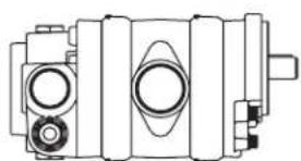
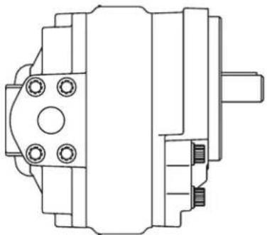
Single gear pump with tandem backplate
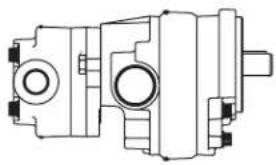
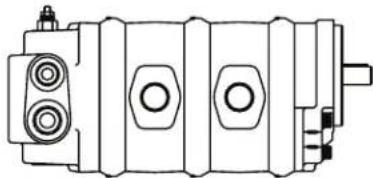
natural_image
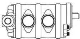
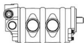
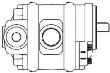
Technical line drawing of a mechanical pump or motor assembly (no text or symbols)Double gear pump with tandem backplate
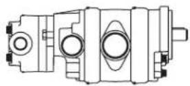
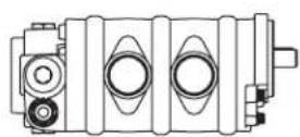
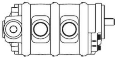
Triple gear pump with two suction ports and tandem backplate
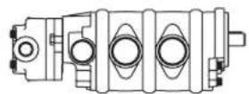
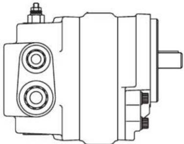
Single gear pump Double gear pump with common suction port
natural_image
Technical line drawing of a mechanical component with no visible text or symbols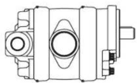
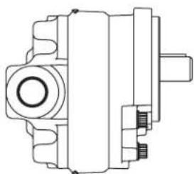
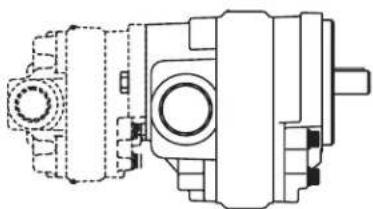
natural_image
Technical line drawing of a mechanical component with no visible text or symbolsSingle gear pump w/ tandem flow divider backplate
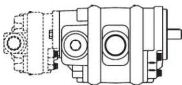
natural_image
Technical line drawing of a mechanical assembly (no text or symbols)Double gear pump with tandem flow divider backplate
Triple gear pump with two suction ports
Triple gear pump with two suction ports and tandem flow divider backplate
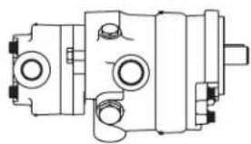
Single gear pump with relief valve
natural_image
Technical line drawing of a mechanical component with no visible text or symbolsDouble gear pump with relief valve
natural_image
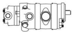
Technical line drawing of a mechanical component with no visible text or symbolsSingle gear pump with flow divider and relief valve
natural_image
Technical line drawing of a mechanical component with no visible text or symbolsDouble gear pump with flow divider and relief valve
natural_image
Technical line drawing of a mechanical component with no visible text or symbolsTriple gear pump with two suction ports and relief valve
Triple gear pump with two suction ports, flow divider and relief valve
Series 26 pump
Component parts - dimensions
Front plate
SAE A 2 bolt flange used on all standard catalog assemblies
"B" Mount
![15.0 [.59] 6.4 [.25] Dia. 82.52±.03 [3.249±.001] 30.4 130.0 [5.12] 106.4 [4.19] 47.6 [1.88] 83.3 [3.28] 2X Dia. 11.56±.1 3](/content/2026/04/623181/images/020c2a8570abf8462aa00e98e94d2e48d173654423cc68e206390b0d5f5c4b2a.jpg)
![2X Ø 14,27 [.562] Ø101,58 +/-0,03 [3.999 +/- .0 01] 9,4 [.37] Intergrated plot does not allow e engaging. A device sealant must be used in weimountapollations. 146,0 [5.75]](/content/2026/04/623181/images/f073369ca38a39fc6ac91cebb4ac2b5536455d665875b5eed546c9a6ed491466.jpg)
4 Bolt euro mount
![4 Bolt euro mount 90 [3.54] 45 [1.77] 4X 9.1 [36] 4X 45° 34,5 [1.36] 100,1 [3.94] 47,8 [1.88] 125,7 [4.95] 134,9 [5.31] 72,1 [2.84] 36,1 [1.42] Ø 79.92 +/-0,03 [3.146 +/- 0.001] 7,1 [.28]](/content/2026/04/623181/images/fe5a00841502bbf0bff6dd7505d52285567b6bf01ec0577c0ab684501ffb7555.jpg)
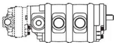
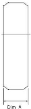
Body
Used on single and multiple pumps
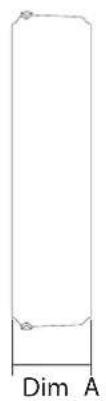
natural_image
Simple line drawing of a vertical rectangle with base labeled 'Dim A' (no other text or symbols)Model 26001 26002 26003 26004 26005 26006 26007
| Displacement (cm3/r [in3/r]) | 6.6 [.40] | 8.2 [.50] | 9.5 [.58] | 10.8 [.66] | 13.8 [.84] | 16.7 [1.02] | 19.7 [1.20] |
| Dimension A (mm [in]) | 14.4 [.57] | 16.3 [.64] | 17.7 [.70] | 19.5 [.77] | 22.7 [.89] | 25.9 [1.02] | 29.1 [1.15] |
Model 26008 26009 26010 26011 26012 26013
| Displacement (cm3/r [in3/r]) | 22.5 [1.37] | 24.3 [1.48] | 25.2 [1.54] | 27.7 [1.69] | 29.0 [1.77] | 30.6 [1.87] |
| Dimension A (mm [in]) | 32.3 [1.27] | 34.7 [1.36] | 35.5 [1.40] | 38.7 [1.52] | 40.3 [1.59] | 41.9 [1.65] |
All dimensions are in mm [in].
Backplate
Used on single and multiple pumps
![C 25.9 [1.02] 21.1 [.83] 18 [.71] Riveshaftd centerlin e 18 [.71] Suction port side porting Suction port rear porting 46.2 [1.82] 92.5 [3.64] Pressure re port rear porting Pressure port side portin g 27.7 [1.09] 48.3 [1.90] Left hand rotation shown](/content/2026/04/623181/images/5d6e70a0156277d1c5319dbae5e88db1511e7276a16f5f7cbba327bf44c55e99.jpg)
Flow divider backplate
Used on single and multiple pumps
![Flow divider backplate Used on single and multiple pumps Secondary pressure port rear porting Secondary pressure port side portin g 1.3 [.05] 38.1 [1.50] Priority pressure portside porting Priority pressure port rear porting C L 19.3 [.76] 30.2 [1.19] 48.8 [1.92] 55.1 [2.17] 90.9 [3.58] Relie f valve Suction port (No relief valve) rear porting Suction port side portin g 18 [.71] Driveshaft centerlin e 63.8 [2.51] 79.8 [3.14] 45.5 [1.79] 70.1 [2.76] Right hand rotation shown](/content/2026/04/623181/images/5495be82061d9bd30620f447eca7d9c368ca99ab5f84e9c8888d9b47f0dff50d.jpg)
Right hand rotation shown
All dimensions are in mm [in].
Series 26 pump
Component parts - dimensions
Relief valve backplate
Adaptor plate
Used on single and multiple pumps - right hand rotation show Used on multiple pumps - right hand rotation shown
![Pressure port side porting Pressure port rear porting C L 66 [2.60] 11.7 [.46] Relief Valve 18.1 [.71] 21.8 [.86] 58.5 [2.31] Driveshaf t centerline Relief valve external drain 7/8-14SA E 39.1 [1.54] Suction port side portin g Suction port rear porting 21.1 [.83] 25.9 [1.02] 47.8 [1.88] 95.5 [3.76] 27.7 [1.09] 52.3 [2.06]](/content/2026/04/623181/images/179f2d7db5f7d748f5c065638b95edcde2a9276f4fc0120c3b53974ba6757b16.jpg)
![C L 18.1 [.71] Pressure port 46.2 [1.82] 62.7 [2.47] Driveshaft centerlin e Suction n port 48.3 [1.90]](/content/2026/04/623181/images/81af5b1f62baf7573a3da7973d08105b633d7c55204c2b7440ef415d8fea5d0b.jpg)
Tandem backplate
Used on single and multiple pumps SAE AA 2 bolt flange
![15,7 [.62]](/content/2026/04/623181/images/03074b7b80e32112a48613213de8c4346caff121f8008a6efed3a4244f7144ed.jpg)
9 tooth 20/40 DP 30°
invlt flat rootclass I
side fit spline SAE J498b
9,7 [.38] min. full spline
Max torque rating: 29.5 Nm [261 lb
![See model code for outputhaft options Pressure port 82.5 C [3.25] L 46.2 [1.82] 92.5 [3.64] 2X 3/8-16 18 [.71] Driveshaft t centerlin e Suctio n port 50.8 [2.00] 20.8 [.82]](/content/2026/04/623181/images/b39772f64edfda233fcac802eca231dc19951b3f1ab165a7fd2a82c4445d2e4a.jpg)
Right hand rotation shown
All dimensions are in mm [in].
Series 26 gear pumps can be ordered by using the following model code.
A twenty-four digit coding system has been designed to identify the features presently available on single gear pumps. The characters and their relative positions within the code identify specific features.
Use the model code matrix as an aid when assembling the model code for the pump with the features you desire. It may be helpful to photocopy the matrix and write the numbers and letters into the boxes as you select features.
All twenty-four digits of the code must be submitted when ordering.
| ACN | * | * | ** | ** | A | 0 | 00 | 00 | 00 | 0 | 00 | 00 | 0 | 0 | A |
| 1 | 2 | 3 | 4 | 5 | 6 | 7 | 8 | 9 | 10 | 11 | 12 | 13 | 14 | 15 |
1 2 3 26 Series
ACN Gear pump - single unit
4 Unit type
A Plain
B Flow divider with/without relief valve (pos. 14-15)
C Relief valve (pos.16-17)
5 Input rotation (viewed from input shaft end)
L Left-hand rotation CCW R Right-hand rotation CW
6 7 Displacement (cm³/r [in³/r])
1 6.6 [.40]
2 8.2 [.50]
3 9.5 [.58]
4 10.8 [.66]
5 13.8 [.84]
6 16.7 [1.02]
7 19.7 [1.20]
8 22.5 [1.37]
9 24.3 [1.48]
10 25.2 [1.54]
11 27.7 [1.69]
12 29.0 [1.77]
13 30.6 [1.87]
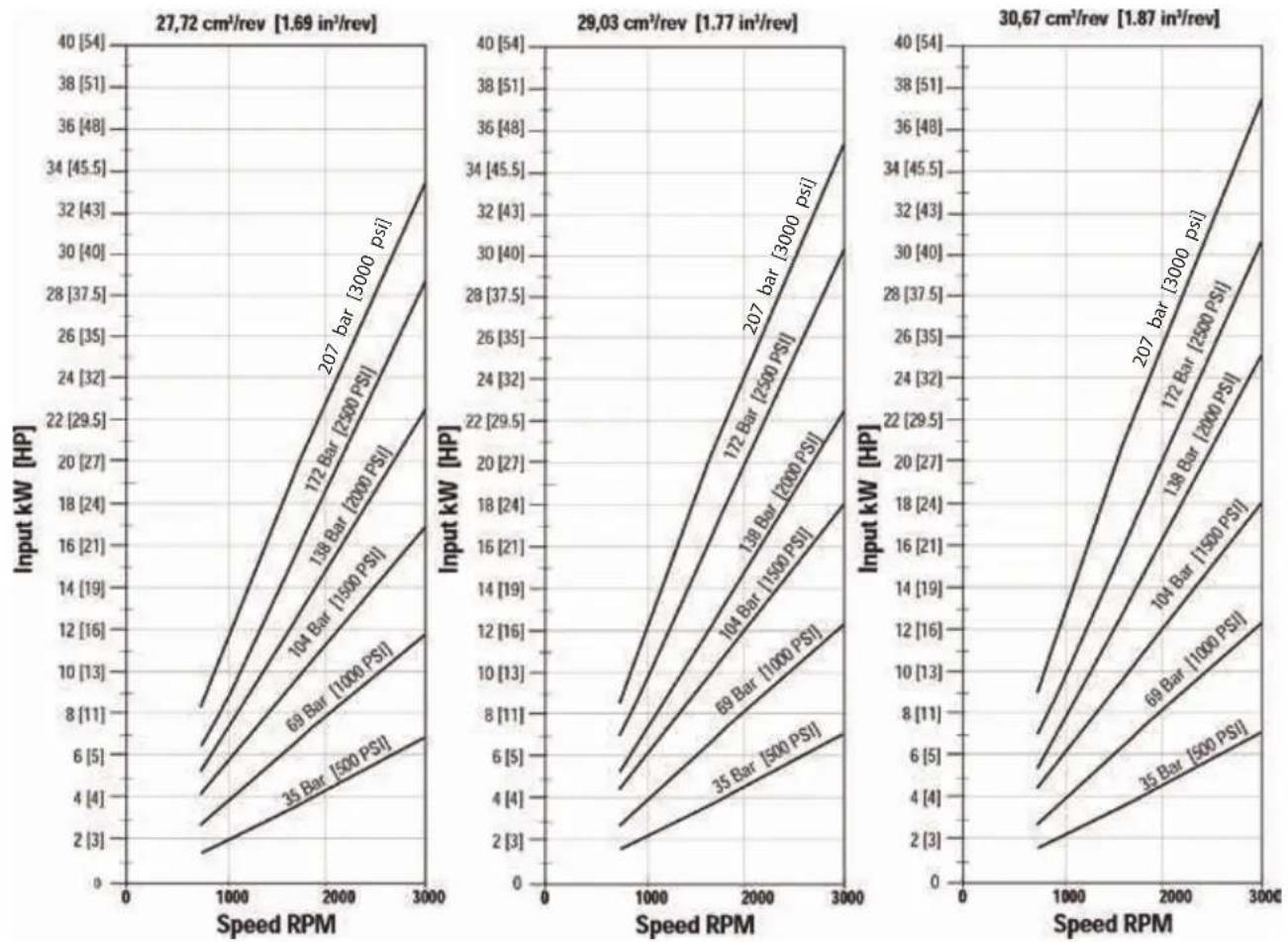
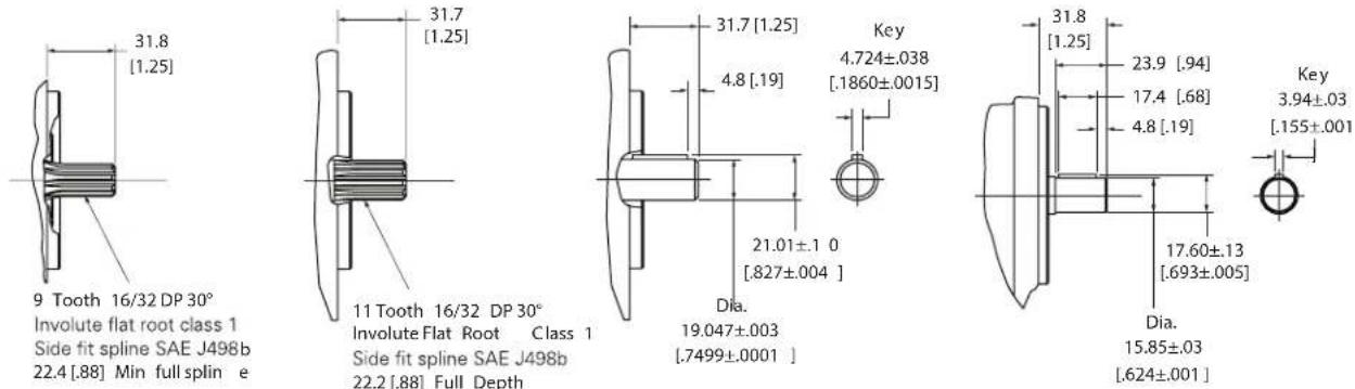
8 9 Input shaft
AA 5/8 Inch dia . 9 Tooth spline 16/32 pitch shaft extension 31 .8 [1.25]
AB 3/4 Inch dia. 11 Tooth spline 16/32 pitch shaft extension 31 .8 [1.25]
AC 3/4 Inch dia. Straight keyed, keyway 4 .8 X 25.4 [.19 X 1 .00] Shaft extension 31 .8 [1.25]
AD 5/8 Inch dia. Straight keyed, keyway 4 .1 X 18.3 [.16 X .72] Shaft extension 31 .8 [1.25]
10 Mounting features
A SAE 2-bolt a flange, series 82-2
B SAE 2-bolt A flange with thru drain
C SAE 2-bolt b flange, series 101-2
D European 4-bolt
11 Auxiliary mounting features
0 No rear mounting
C (2-Bolt AA) SAE flange series 50-2, with 9 tooth internal spline 20/40 pitch, accepts 25.4 [1.00] Shaft extension
12 13 Ports, sizes and location- backplate
1 Plain: suction port 1 .3125-12 UN-2B SAE O-ring port; pressure port .875-14 UNF-2B SAE O-ring port - side sports
2 Plain: suction port 1 .3125-12 UN-2B SAE O-ring port; pressure port .875-14 UNF-2B SAE O-ring port - rear ports
3 Plain: suction port 1 .0625-12 UN-2B SAE O-ring port; pressure port .875-14 UNF-2B SAE O-ring port accepts fittings per SAE J1926 - side ports
4 Plain: suction port 1 .0625-12 UN-2B SAE O-ring port; pressure port .875-14 UNF-2B SAE O-ring port accepts fittings per SAE J1926 -rear ports
08 Plain thru shaft: suction port 1 .0625-12 UN-2B SAE Oring port; pressure port.875-14 UNF-2B SAE O-ring port - side ports
15 Relief valve: suction port 1 .0625-12 UN-2B SAE O-ring port; pressure port .875-14 UNF-2B SAE O-ring port - side ports; drain port .875-14 UNF-2B SAE O-ring port
16 Relief valve: suction port 1 .0625-12 UN-2B SAE O-ring port; pressure port .875-14 UNF-2B SAE O-ring port - rear ports; drain port .875-14 UNF-2B SAE O-ring port
20 Flow divider: suction port 1 .3125-12 UN-2B SAE O-ring port; priority pressure port .750-16 UNF-2B SAE Oring port; secondary pressure port .875-14 UNF-2B SAE Oring Port - Side Ports
Series 26 pump Model code single

21 Flow Divider: Suction Port 1.3125-12 UN-2B SAE O-ring Port; Priority Pressure Port .750-16 UNF-2B SAE Oring Port; Secondary Pressure Port .875-14 UNF-2B SAE Oring Port - Rear Ports
14 15 Priority flow divider setting (LPM [GPM])
00 No Flow Setting
AA 3.8 [1.00]
AD 7.6 [2.00]
AJ 11.4 [3.00]
AL 15.1 [4 .00]
AN 18.9 [5 .00]
AR 22.7 [6 .00]
AS 26.5 [7.00]
AT 30.3 [8 .00]
16 17 Relief valve full flow setting (bar [PSI])
00 No Relief Valve Setting
AA 34 .5 [ 500]
AB 51.7 [750]
AC 68.9 [1000]
AE 86.2 [1250]
AF 103.4 [1500]
AJ 120.7 [1750]
AL 137.9 [2000]
AN 155 .1 [2250]
AP 172.4 [2500]
AR 189.6 [2750]
AS 206.8 [3000]
BR 241.3 [3500]
BT 224.1 [3250]
18 Test Data
0 Generic
A A - Unit Specific (required for flow divider and relief valve options.)
19 20 Special features
00 No Special Features
AB Viton Shaft Seal
21 22 Paint
00 None
OA Red Primer
OB Black
23 Identification
0 Standard
24 Design code
A A
Series 26 Gear Pumps can be ordered by using the following Model Code.
A thirty-two digit coding system has been designed to identify the features presently available on Multiple gear
pumps. The characters and their relative positions within the code identify specific features. Use the Model Code Matrix as an aid when assembling the model code for the pump with the features you desire .It may be helpful
to photocopy the matrix and write the numbers and letters into the boxes as you select features.
All thirty-two digits of the code must be submitted when ordering.
| ACM | * | * | ** | ** | ** | ** | ** | ** | ** | 00 | 00 | A | 0 | 0 | 00 | 00 | 0 | B |
| 1 | 2 | 3 | 4 | 5 | 6 | 7 | 8 | 9 | 10 | 11 | 12 | 13 | 14 | 15 | 16 | 17 | 18 | 19 |
1 2 3 26 Series
| ACM | Gear Pump - Multiple Unit | |
| 4 | Unit type | |
| A Plain | ||
| B | Flow Divider with/without Relief Valve (Pos. 20-21) | |
| C | Relief Valve | |
| 5 | Input rotation (viewed from input shaft end) | |
| L | Left-hand Rotation CCW | |
| R | Right-hand Rotation CW | |
| 6 | 7 | Displacement - front ( cm^3/r [ in^3/r ]) |
| 1 6.6 [.40] | ||
| 2 8.2 [.50] | ||
| 3 9.5 [.58] | ||
| 4 10.8 [.66] | ||
| 5 13.8 [.84] | ||
| 6 16.7 [1.02] | ||
| 7 19.7 [1.20] | ||
| 8 22.5 [1.37] | ||
| 9 24. 3 [1.48] | ||
| 10 25.2 [1.54] | ||
| 11 27.7 [1.69] | ||
| 12 29.0 [1.77] | ||
| 13 30.6 [1.87] | ||
| 8 | 9 | Displacement - Ctr. triple only ( cm^3/r [ in^3/r ]) |
| 1 6.6 [.40] | ||
| 2 8.2 [.50] | ||
| 3 9.5 [.58] | ||
| 4 10.8 [.66] | ||
| 5 13.8 [.84] | ||
| 6 16,7 [1.02] | ||
| 7 19.7 [1.20] | ||
| 8 22.5 [1.37] | ||
| 9 24. 3 [1.48] | ||
| 10 25.2 [1.54] | ||
| 11 27.7 [1.69] | ||
| 12 29.0 [1.77] | ||
| 13 30.6 [1.87] | ||
| 99 No Center Displacement | ||
10 11 Displacement - front (cm³/r [in³/r])
| 1 | 6.6 [.40] | |
| 2 | 8.2 [.50] | |
| 3 | 9.5 [.58] | |
| 4 | 10.8 [.66] | |
| 5 | 13.8 [.84] | |
| 6 | 16.7 [1.02] | |
| 7 | 19.7 [1.20] | |
| 8 | 22.5 [1.37] | |
| 9 | 24.3 [1.48] | |
| 10 | 25.2 [1.54] | |
| 11 | 27.7 [1.69] | |
| 12 | 29.0 [1.77] | |
| 13 | 30.6 [1.87] | |
| 12 13 | Input shaft | |
| AA | 5/8 Inch Dia . 9 Tooth Spline 16/32 Pitch Shaft Extension 31 .8 [1.25] | |
| AB | 3/4 Inch Dia . 11 Tooth Spline 16/32 Pitch Shaft Extension 31 .8 [1.25] | |
| AC | 3/4 Inch Dia . Straight Keyed, Keyway 4 .8 x 25.4 [.19 x 1 .00] Shaft Extension 31 .8 [1.25] | |
| AD | 5/8 Inch Dia . Straight Keyed, Keyway 4 .1 X 18.3 [.16 X .72] Shaft Extension 31 .8 [1.25] | |
| 14 15 | Front adapter ports | |
| 01 | Suction Port 1-5/8–12 UN-2B SAE O-ring Port; Pressure Port 7/8–14 UNF-2B SAE O-ring Port | |
| 05 | Suction Port 1-5/16–12 UN-2B SAE O-ring Port; Pressure Port 7/8–14 UNF-2B SAE O-ring Port | |
| 16 17 | Ports - rear adapter (triple units) | |
| 0 | No Rear Adaptor | |
| 1 | Suction Port 1-5/8–12 UN-2B SAE O-ring Port; Pressure Port 7/8–14 UNF-2B SAE O-ring Port | |
| 05 | 05 = Suction Port 1-5/16–12 UN-2B SAE O-ring Port; Pressure Port 7/8–14 UNF-2B SAE O-ring Port | |
Series 26 pump Model code multiple
| ACM | * | * | ** | ** | ** | ** | ** | ** | ** | ** | 00 | 00 | A | 0 | 0 | 00 | 00 | 0 | B |
| 1 | 2 | 3 | 4 | 5 | 6 | 7 | 8 | 9 | 10 | 11 | 12 | 13 |
18 19 Ports, sizes and location- backplate
1 Plain: Suction Port 1-5/16–12 UN-2B SAE O-ring Port Size; Pressure Port 7/8–14 UNF-2B SAE O-ring Port-Side Ports
2 Plain: Suction Port 1-5/16–12 UN-2B SAE O-ring Port Size; Pressure Port 7/8–14 UNF-2B SAE O-ring Port-Rear Ports
3 Plain: Suction Port 1-1/16–12 UN-2B SAE O-ring Port Size; Pressure Port 7/8–14 UNF-2B SAE O-ring Port-Side Ports
4 Plain: Suction Port 1-1/16-12 UN-2B SAE O-ring Port Size; Pressure Port 7/8-14 UNF-2B SAE O-ring Port-Rear Ports
08 Plain Tandem: Suction Port 1 .0625-12 UN-2B SAE Oring Port; Pressure Port.875-14 UNF-2B SAE O-ring Port - Side Ports
14 Plain: Suction Port 1-5/16–12 UN-2B SAE O-ring Port Size-(Plugged); Pressure Port 7/8–14 UNF-2B SAE O-ring Port-Side Ports, used with position 14 and 15–01 and 16 and 17–10
17 Plain: Suction Port 1-5/16–12 UN-2B SAE O-ringPort Size-(Plugged); Pressure Port 7/8–14 UNF-2B SAE O-ring Port-Rear Ports, used with position 14 and 15–01 and 16 and 17–01
18 Plain Tandem: Suction Port 1 .0625-12 UN-2B SAE Oring Port (Plugged); Pressure Port .875-14 UNF-2B SAE Oring Port - Side Ports
19 Plain: Suction Port 1 .3125-12 UN-2B SAE O-ring Port (Plugged); Pressure Port 1.0625-12 UN-2B SAE O-ring Port - Side Ports
20 Relief Valve: Suction Port 1 .0625-12 UN-2B SAE O-ring Port; Pressure Port .875-14 UNF-2B SAE O-ring Port - SIDE Ports; DRAIN Port .875-14 UNF-2B SAE O-ring Port
21 Relief Valve: Suction Port 1 .0625-12 UN-2B SAE O-ring Port; Pressure Port .875-14 UNF-2B SAE O-ring Port - Rear Ports; DRAIN Port .875-14 UNF-2B SAE O-ring Port - TOP Port
27 Flow Divider: Suction Port 1.3125-12 UN-2B SAE Oring Port; Priority Pressure Port .750-16 UNF-2B SAE Oring Port; Secondary Pressure Port .875-14 UNF-2B SAE Oring Port - SIDE Ports
28 Flow Divider: Suction Port 1.3125-12 UN-2B SAE Oring Port; Priority Pressure Port .750-16 UNF-2B SAE Oring Port; Secondary Pressure Port .875-14 UNF-2B SAE Oring Port - Rear Ports
29 Flow Divider: Suction Port 1 .0625-12 UN-2B SAE Oring Port; Priority Pressure Port .5625-18 UNF-2B SAE Oring Port; Secondary Pressure Port .875-14 UNF-2B SAE Oring Port - SIDE Ports
Consult your Danfoss representative when requiring common inlet option.
| 20 21 | Priority flow divider setting (LPM [GPM]) |
| 00 No Flow Setting | |
| AA 3.8 [1.00] | |
| AD 7.6 [2.00] | |
| AJ 11.4 [3 .00] | |
| AL 15.1 [4 .00] | |
| AN 18.9 [5 .00] | |
| AR 22.7 [6 .00] | |
| AS 26.5 [7.00] | |
| AT 30.3 [8 .00] |
22 23 Relief valve full flow setting (bar [PSI])
00 No Relief Valve Setting
| AA | 34.5 [500] |
| AB | 51.7 [750] |
| AC | 68.9 [1000] |
| AE | 86.2 | [1250] |
| AF | 103.4 [1500] |
| AJ | 120.7 [1750] |
| AL | 137.9 [2000] |
| AN | 155.1 [2250] |
| AP | 172.4 [2500] |
| AR | 189.6 [2750] |
| AS | 206.8 [3000] |
| ACM | * | * | ** | ** | ** | ** | ** | ** | ** | 00 | 00 | A | 0 | 0 | 00 | 00 | 0 | B |
| 1 | 2 | 3 | 4 | 5 | 6 | 7 | 8 | 9 | 10 | 11 | 12 | 13 | 14 | 15 | 16 | 17 | 18 | 19 |
24 Mounting features (front)
A (2-Bolt A) SAE Flange, Series 82-3
C (2-Bolt B) SAE Flange Series 82 .3
G (4-Bolt) European
25 Auxiliary mounting features
0 No Rear Mounting
C (2-Bolt AA) SAE Flange Series 50-2, with 9 Tooth Internal Spline 20/40 Pitch, Accepts 25.4 [1.00] Shaft Extension
26 Test data
0 Generic
A Unit Specific (required for flow divider and relief valve options.)
27 28 Special features
00 No Special Features
AB Viton Shaft Seal
29 30 Paint
00 None
0A Red Primer
OB Black
31 Identification
0 Standard
32 Design code
B B
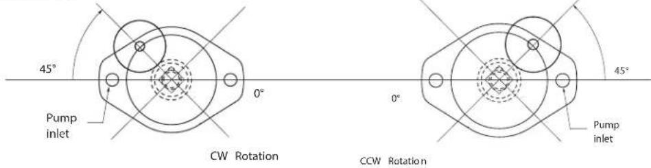
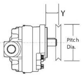
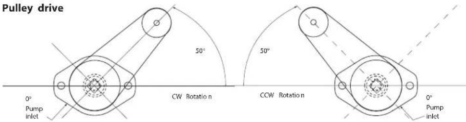
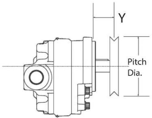
Series 26 pump Side-load applications
Maximum allowable operating pressures
Ideal positions shown. Side load is acceptable within 90° of either side of the ideal position. Charts are based on 100% slack side tension. Max. speed per catalog. Max. operating pressure shown.
Gear drive
0.40/0.50 CID 0.58/0.66 CID
Pulley ∅ 2 4 6 8 10 12
| Gear pitch ∅ 1 2 3 4 5 6 | |||||||
| Y Dimension | |||||||
| 2.0" | 3000 | 3000 | 3000 | 3000 | 3000 | ||
| 1.5" | 3000 | 3000 | 3000 | 3000 | 3000 | 3000 | |
| 1.0" | 3000 | 3000 | 3000 | 3000 | 3000 | 3000 | |
| 0.5" | 3000 | 3000 | 3000 | 3000 | 3000 | 3000 | |
| 0" | 3000 | 3000 | 3000 | 3000 | 3000 | 3000 | |
Pulley ∅ 2 4 6 8 10 12
| Gear pitch ∅ 1 2 3 4 5 6 | |||||||
| Y Dimension | |||||||
| 2.0" | 2250 | 3000 | 3000 | 3000 | 3000 | ||
| 1.5" | 2250 | 3000 | 3000 | 3000 | 3000 | 3000 | |
| 1.0" | 2500 | 3000 | 3000 | 3000 | 3000 | 3000 | |
| 0.5" | 2500 | 3000 | 3000 | 3000 | 3000 | 3000 | |
| 0" | 2750 | 3000 | 3000 | 3000 | 3000 | 3000 | |
.84 CID 1.02 CID
Pulley ∅ 2 4 6 8 10 12
| Gear pitch ∅ 1 2 3 4 5 6 | |||||||
| Y Dimension | |||||||
| 2.0" | 1750 | 2500 | 3000 | 3000 | 3000 | ||
| 1.5" | 1750 | 2750 | 3000 | 3000 | 3000 | 3000 | |
| 1.0" | 2000 | 2750 | 3000 | 3000 | 3000 | 3000 | |
| 0.5" | 2000 | 3000 | 3000 | 3000 | 3000 | 3000 | |
| 0" | 2250 | 3000 | 3000 | 3000 | 3000 | 3000 | |
Pulley ∅ 2 4 6 8 10 12
| Gear pitch ∅ 1 2 3 4 5 6 | |||||||
| Y Dimension | |||||||
| 2.0" | 1250 | 2000 | 2250 | 2500 | 2750 3000 | ||
| 1.5" | 1250 | 2000 | 2500 | 2750 | 3000 | 3000 | |
| 1.0" | 1250 | 2000 | 2500 | 2750 | 3000 | 3000 | |
| 0.5" | 1500 | 2250 | 2500 | 2750 | 3000 | 3000 | |
| 0" | 1500 | 2250 | 2750 | 3000 | 3000 | 3000 | |
Maximum allowable operating pressures
Ideal positions shown. Side load is acceptable within 90° of either side of the ideal position. Charts are based on 100% slack side tension. Max.speed per catalog. Max.operating pressure shown.
1.20 CID
Pulley ∅ 2 4 6 8 10 12
Gear pitch ∅ 1 2 3 4 5 6
Y Dimension
| 2.0" | N/R | 1500 | 2000 | 2250 | 2250 | 2500 |
| 1.5" | N/R | 1500 | 2000 | 2250 | 2500 | 2500 |
| 1.0" | N/R | 1750 | 2000 | 2250 | 2500 | 2500 |
| 0.5" 1250 1750 2250 2250 2500 2750 | ||||||
| 0" 1250 1750 2250 2500 2750 3000 | ||||||
1.69 CID
Pulley ∅ 2 4 6 8 10 12
Gear pitch ∅ 1 2 3 4 5 6
Y Dimension
| 2.0" | N/R | N/R | 1250 | 1500 | 1500 | 1750 | ||||
| 1.5" | N/R | N/R | 1250 | 1500 | 1500 | 1750 | ||||
| 1.0" | N/R | N/R | 1250 | 1500 | 1750 | 1750 | ||||
| 0.5" | N/R | 1250 | 1250 | 1500 | 1750 | 1750 | ||||
| 0" | N/R | 1250 | 1500 | 1750 | 1750 | 2000 | ||||
1.37 CID
Pulley ∅ 2 4 6 8 10 12
Gear pitch ∅ 1 2 3 4 5 6
Y Dimension
2.0" N/R 1250 1750 2000 2000 2250
1.5" N/R 1250 1750 2000 2000 2250
1.0" N/R 1500 1750 2000 2250 2250
0.5" N/R 1500 1750 2000 2250 2250
0" N/R 1500 1750 2000 2250 2500
.1.48/1.54 CID
Pulley ∅ 2 4 6 8 10 12
Gear pitch ∅ 1 2 3 4 5 6
Y Dimension
2.0" N/R N/R 1250 1500 1750 2000
1.5" N/R 1250 1500 1750 1750 2000
1.0" N/R 1250 1500 1750 2000 2000
0.5" N/R 1250 1500 1750 2000 2000
0" N/R 1500 1750 2000 2000 2250
1.77/1.87 CID
Pulley ∅ 2 4 6 8 10 12
Gear pitch ∅ 1 2 3 4 5 6
Y Dimension
| 2.0" | N/R | N/R | N/R | 1250 | 1500 | 1500 | ||
| 1.5" | N/R | N/R | 1250 | 1250 | 1500 | 1500 | ||
| 1.0" | N/R | N/R | 1250 | 1250 | 1500 | 1500 | ||
| 0.5" | N/R | N/R | 1250 | 1500 | 1500 | 1750 | ||
| 0" | N/R | N/R | 1250 | 1500 | 1750 | 1750 |
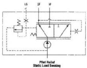
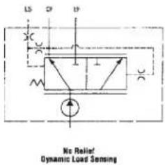
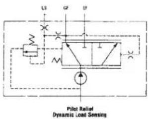
Series 26 pump Load sensing priority valve
The Load Sensing Priority Valve is used with the open loop load sense systems that are typically used in steering and braking circuits. The load sense gear pump provides metered priority flow (CF) on demand.
The excess flow (EF) is available for auxiliary circuits. The response time was selected to insure that the operator will not sense a delay or steering "kick" during transient conditions.
Valve specifications
| Rated Pressure 207 BAR (3000PSI) |
| Rated Inlet Flow 108 L/m (28GPM) |
| Maximum Controlled Flow (CF) 33 L/m(8.5 GPM) |
| Bias Pressure Dynamic - 10 bar (150 PSI) Std. Static - 6.9 bar (100 PSI) Std. |
| Relief Pressure 34.5-207 bar (500-3000 PSI) |
| Response Time 70 msec. max. (std. bias spring) |
Pump specifications
| Displacements | 9 Available: 8.2 cm^3r 50in^3/r thru 30.6 cm ^3 /r [1.87in ^3 /r] |
| Mounting SAE 2-Bolt A Mount | SAE 2-Bolt B Mount4-Bolt European Mount (80mm Pilot) |
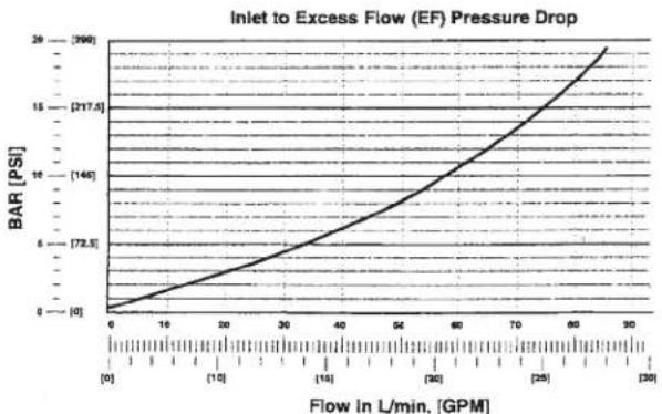
line
| Flow in L/min. [GPM] | BAR [PS] | | ------------------- | -------- | | 0 | 0 | | 10 | 2 | | 20 | 4 | | 30 | 6 | | 40 | 8 | | 50 | 10 | | 60 | 12 | | 70 | 14 | | 80 | 16 | | 90 | 18 |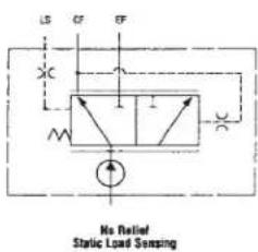
| Rotation | Bi-Rotation |
| Mounting Flange | SAE A 2 Bolt |
| Max. Continuous Pressure† | 210 bar [3000 PSI]* |
| Max. Intermittent Pressure†† | 240 bar [3500 PSI]** |
| Minimum Speed at Continuous Pressure | 750 RPM |
| Maximum Rotating Torque at 0 Pressure | 4 Nm [36 lb-in] |
| Maximum Continuous Operating Temperature | 105°C [220°F] |
| Minimum Continuous Oil Viscocity | 5.7 cSt [45 SUS] |
| Minimum Operating Temperature | -29°C [-20°F] |
| Maximum Inlet Vacuum at Operating Condition | 0,8 bar Abs. [11.6 psi Abs.] |
| Maximum Thrust Load | 50 lbs. |
| Maximum Seal Pressure | 150 PSI, 200 PSI @ 1500 RPM |
† Continuous - motor may be run continuously at these ratings.
++ Intermittent - intermittent operation, 10% of every minute.
* 31.8 cm³/rev . [1.94 in³/rev.] displacement max. continuous pressure is 190 bar [2750 PSI].
** 31.8 cm ^3 /rev. [1.94 in ^3 /rev.] displacement max. intermittent pressure is 224 bar [3250 PSI]. For side load limits consult your Danfoss representative.
| Displacement cm^3/r [ in^3/r ] | 7,0[.43] | 8,8[.54] | 10,1[.62] | 11,6[.71] | 14,5[.88] | 17,3[1.06] | 20,3[1.24] |
| Max. Intermittent Pressure bar [PSI] | 241[3495] | 241[3495] | 241[3495] | 241[3495] | 241[3495] | 241[3495] | 241[3495] |
| Rated Speed (RPM) | 3600 | 3600 | 3600 | 3600 | 3600 | 3200 | 3200 |
| Minimum Output Flow at Continuous Rated Speed and Pressure LPM [GPM] | 22,2[5.9] | 27,9[7.4] | 32,0[8.5] | 36,7[9.7] | 48,0[12.7] | 50,9[13.5] | 59,8[15.8] |
| Displacement cm^3/r [ in^3/r ] | 23,1[1.41] | 25,2[1.54] | 26,0[1.59] | 28,8[1.76] | 30,3[1.85] | 31,7[1.93] |
| Max. Intermittent Pressure bar [PSI] | 241[3495] | 241[3495] | 241[3495] | 241[3495] | 234[3393] | 224[3248] |
| Rated Speed (RPM) | 3000 | 3000 | 3000 | 3000 | 3000 | 3000 |
| Minimum Output Flow at Continuous Rated Speed and Pressure LPM [GPM] | 63,8[16.8] | 69,6[18.4] | 71,8[19.0] | 79,5[21.0] | 83,6[22.1] | 87,5[23.1] |
The performance data in the table above and the following graphs was collected using a mineral base oil with a viscosity of 133 SUS at 49^ [120°F].
Ordering information
Catalog assemblies cross reference
Standard catalog assemblies are built from high production parts and are the most economical pump assemblies available in this series. The standard assembly order number is a preassigned part number and may be used to order the specific standard assembly (see page 27).
Series 26 Motor Performance Data
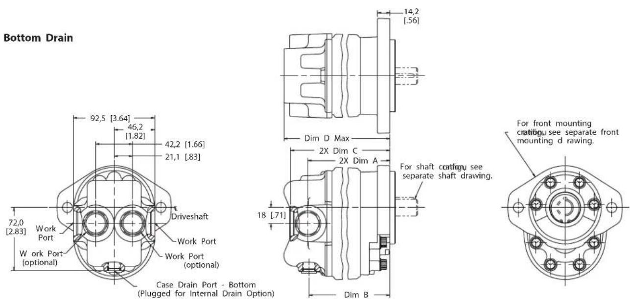
Top Drain
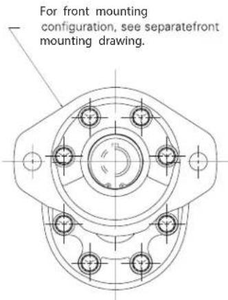
![92,5 [3.64] 46,2 [1.82] Case D rain Po rt - Top (Plugged fo r Inte rnal Drain Option) 42,2 [1.66] 21,1 [.83] 35,7 [1,41] Driveshaft Work Port Work Po rt (optional) Work Po rt (optional)](/content/2026/04/623181/images/59d6ee2f0a8ed949c9fd25f14792840af41c6052d9e7fcb39a6c2cfaf3ac662e.jpg)
Front mount: 2 bolt SAE A and B
| Displacement Dim A | Dim B Dim C Dim D | ||
| cm^3/r [ln ^3/r ] mm [ln] mm [ln] mm [ln] mm [ln] | |||
| 7.0 [.43] | 69.2 [2.72] 67.9 [2.67] | 89.0 [3.50] 96.6 [3.80] | |
| 8.8 [.54] | 71.1 [2.80] 69.8 [2.75] 90.9 [3.58] 98.5 [3.88] | ||
| 10.2 [.62] | 72.6 [2.86] 71.3 [2.81] | 92.4 [3.64] 100.0 [3.94] | |
| 11.6 [.71] | 74.3 [2.93] 73.0 [2.88] | 94.1 [3.71] | 101.7 [4.01] |
| 12.5 [.76] | 75.2 [2.96] 74.0 [2.91] | 95.1 [3.74] | 102.7 [4.04] |
| 14.6 [.89] | 77.5 [3.05] 76.2 [3.00] | 97.3 [3.83] | 104.9 [4.13] |
| 17.4 [1.06] | 80.7 [3.18] 79.4 [3.13] | 100.5 [3.96] | 108.1 [4.26] |
| 20.3 [1.24] | 83.9 [3.30] 82.6 [3.25] 103.7 [4.08] | 111.3 [4.38] | |
| 23.1 [1.41] | 87.1 [3.43] 85.8 [3.38] | 106.9 [4.21] | 114.5 [4.51] |
| 26.1 [1.59] | 90.3 [3.56] 89.0 [3.51] | 110.1 [4.34] | 117.7 [4.64] |
| 28.8 [1.76] | 93.5 [3.68] 92.2 [3.63] 113.3 [4.46] | 120.9 [4.76] | |
| 31.8 [1.94] | 96.7 [3.81] 95.4 [3.76] | 116.5 [4.59] | 124.1 [4.89] |
Series 26 Gear Pumps can be ordered by using the following Model Code.
A twenty-four digit coding system has been designed to identify the features presently available on Single gear pumps. The characters and their relative positions within the code identify specific features.
Use the Model Code Matrix as an aid when assembling the model code for the pump with the features you desire. It may be helpful to photocopy the matrix and write the numbers and letters into the boxes as you select features.
All twenty-four digits of the code must be submitted when ordering.
| ADM | * | * | ** | ** | A | 00 | 00 | 0 | 00 | 0 | 00 | 00 | 0 | 0 | A |
| 1 | 2 | 3 | 4 | 5 | 6 | 7 | 8 | 9 | 10 | 11 | 12 | 13 | 14 | 15 | 16 |
1 2 3 26 Series
ADM Gear Motor
4 Unit type
A Plain
5 Output rotation
D Bi-Directional
L Left-hand Rotation CCW
R Right-hand Rotation CW
6 7 Displacement (cm^3 /r [in3/r])
1 7.0 [.43]
2 8.8 [.54]
3 10.2 [.62]
4 11.6 [.71]
5 14.6 [.89]
6 17.4 [1.06]
7 17.4 [1.06]
8 23.1 [1.41]
9 25.2 [1.54]
10 26.1 [1.59]
11 28.8 [1.76]
12 30.3 [1.85]
13 31.8 [1.94]
8 9 Output shaft
AA 9 Tooth Spline 16/32 Spline, Min . Full Spline 22.4 [.88], Shaft Extension 31 .8 [1.25]
AB 11 Tooth Spline 16/32 Spline, Min . Full Spline 22 .4 [.88], Shaft Extension 31 . 8 [1.25]
AC Straight Shaft Dia 19 .05 [.750], Keyway 4 .8 x 25 .4 [.19 x 1 .00], Shaft Extension 31 .8 [1.25] (Key Included)
AD Straight Shaft Dia 15 .88 [.625], Keyway 4 .1 x 18 .3 [.16 x .72], Shaft Extension 31 1.25] (Key Included)
AJ Dia 15 .88 [.625], Taper .125:1, .500-20 UNF-2A, Keyway 4 .1 x 17 .5 [.16 x .69], Shaft Extension 43 .7 [1.72] (Key Included)
10 Mounting features
A 2-Bolt A - SAE Flange Series 82-2
Ports, sizes and location- backplate
1 Inlet Port 1 .0625-12 UN-2B SAE O-Ring Port; Outlet Port 1 .0625-12 UN-2B SAE O-Ring Port - Side Ports
2 Inlet Port 1 .0625-12 UN-2B SAE O-Ring Port; Outlet Port 1 .0625-12 UN-2B SAE O-Ring Port - Rear Ports
3 Inlet Port .875-14 UN-2B SAE O-Ring Port; Outlet Port .875-14 UN-2B SAE O-Ring Port - Side Ports
4 Inlet Port .875-14 UN-2B SAE O-Ring Port; Outlet Port .875-14 UN-2B SAE O-Ring Port - Rear Ports
13 14 Case drain
00 No Case Drain
AA .5625-18 UNF-2B SAE O-Ring Port - Bottom
AB .5625-18 UNF-2B SAE O-Ring Port - Top
AC Internal with Bi-Directional Checks, .5625-18 UNF-2B SAE O-Ring Port - Plugged
AD .5625-18 UNF-2B SAE O-Ring Port - Bottom-Plugged
AE .5625-18 UNF-2B SAE O-Ring Port - Top-Plugged
15 Relief valve type
0 No Relief Valve
C Cross-over
16 17 Relief valve setting bar [lbf/in2]
00 No Relief Valve Setting
AA 117.2 [1700]
AB 141.3 [2050]
AC 31.0 [450]
18 Test data
0 Generic
A Unit Specific (Used with Relief Valve)
Series 26 motor
Model code - single

19 20 Special features
00 No Special Features
21 22 Paint
00 None
0A Primer per Spec 209-13A
OB Black per Spec 209-13B
23 Identification
0 Standard
24 Design code
A A
Rotation CCW or CW
| Mounting Flange SAE 2 Bolt B |
| Maximum Continuous† Pressure 248 bar [3600 PSI]* |
| Maximum Intermittent†† Pressure 276 bar [4000 PSI]** |
| Minimum Speed at Continuous Pressure 750 RPM |
| Maximum Continuous Inlet Temperature 107°C [225°F] |
| Minimum Operating Temperature -29°C [-20°F] |
| Maximum Inlet Vacuum at 82°C [180°F] 6.0 In. Hg and Rated Speed |
† Continuous - pump may be run continuously at these ratings.
†† Intermittent - Intermittent operation, 10% of every minute. For side load limits consult your Danfoss representative.
46.7 [2.85] displacement maximum continuous pressure is 224 bar [3250 PSI] 51.1 [3.12] displacement maximum continuous pressure is 207 bar [3000 PSI] 55.2 [3.37] displacement maximum continuous pressure is 190 bar [2750 PSI]
** 46.7 [2.85] displacement maximum intermittent pressure is 252 bar [3650 PSI]
51.1 [3.12] displacement maximum intermittent pressure is 234 bar [3400 PSI]
55.2 [3.37] displacement maximum intermittent pressure is 217 bar [3150 PSI]
natural_image
Two mechanical pump components shown from different angles (no visible text or labels)| Model | 25500 | 25501 | 25502 | 25503 | 25504 | 25505 | 25506 | 25507 | 25508 |
| Displacement cm^3/r [ in^3/r ] | 21.3[1.30] | 25.4[1.55] | 29.2[1.78] | 33.6[2.05] | 38.2[2.33] | 42.8[2.61] | 46.7[2.85] | 51.1[3.12] | 55.2[3.37] |
| Max. Continuous Pressure bar [PSI] | 248[3600] | 248[3600] | 248[3600] | 248[3600] | 248[3600] | 248[3600] | 224[3250] | 207[3000] | 190[2750] |
| Max. Intermittent Pressure bar [PSI] | 276[4000] | 276[4000] | 276[4000] | 276[4000] | 276[4000] | 276[4000] | 252[3650] | 234[3400] | 217[3150] |
| Rated Speed (RPM) | 3500 | 3000 | 3000 | 2750 | 2750 | 2500 | 2500 | 2500 | 2250 |
| Minimum Output Flow at 207 bar [3000 PSI],3 and Rated Speed LPM [GPM] | 64,7[16.2] | 78,0[17.1] | 83,3[20.6] | 94,6[22.0] | 96,1[25.0] | 105,2[25.4] | 115,1[27.8] | 115,1[29.6] |
The performance data in the table above and the following graphs was collected using a mineral base oil with a viscosity of 133 SUS at 49^ [120°F]. The following performance graphs are representative of the series.
+ Continuous - pump may be run continuously at these ratings.
†† Intermittent - Intermittent operation, 10% of every minute.
Ordering information Standard catalog assemblies
Standard Catalog Assemblies are built from high quality production parts and are the most economical pumps available in this series. Dimensions and order numbers for Standard Catalog Assemblies are given on pages 29-30.
Optional configurations
Besides the Standard Catalog Assemblies, the L2 Series has several optional features. Flow divider and tandem backplates are available. Multiple gear pumps can also be built. If a variation from the Standard Catalog Assemblies is required, use the model codes on pages 35-36.
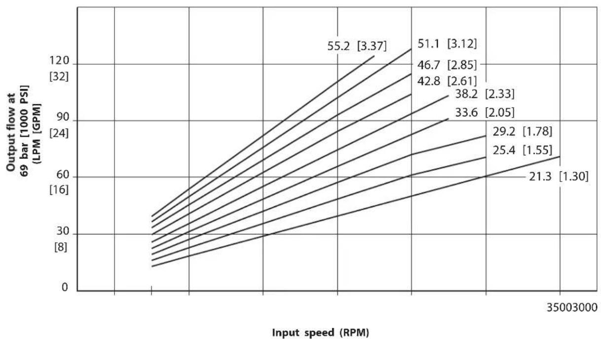
Series L2 pump Performance data charts
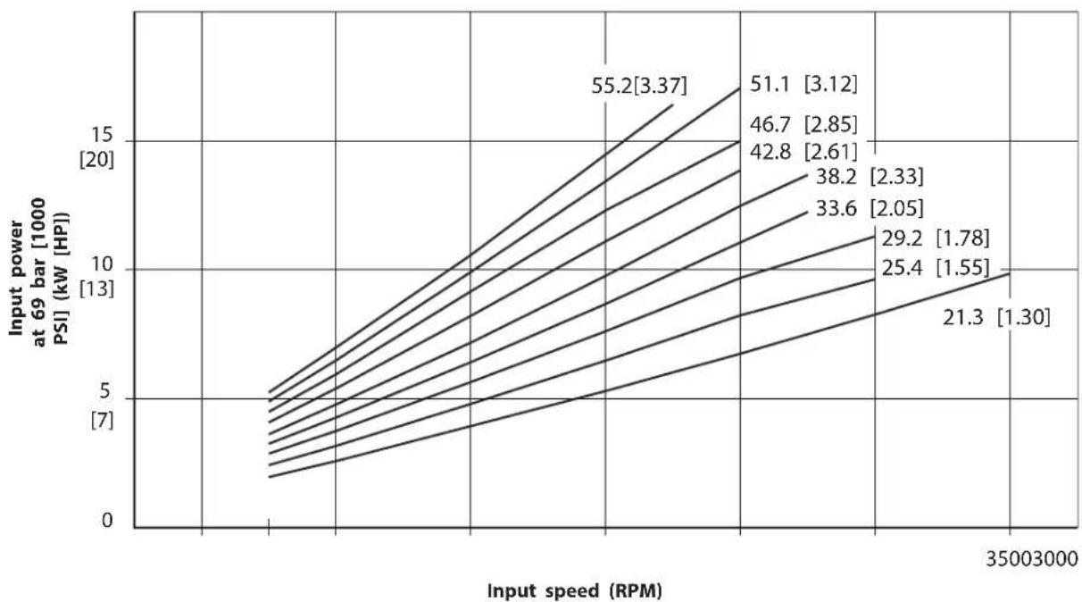
Output power vs speed
line
| Input speed (RPM) | Output flow at 69 bar [1000 PSI] (LPM [GPM]) | | ----------------- | ------------------------------------------- | | 55.2 | 3.37 | | 51.1 | 3.12 | | 46.7 | 2.85 | | 42.8 | 2.61 | | 38.2 | 2.33 | | 33.6 | 2.05 | | 29.2 | 1.78 | | 25.4 | 1.55 | | 21.3 | 1.30 |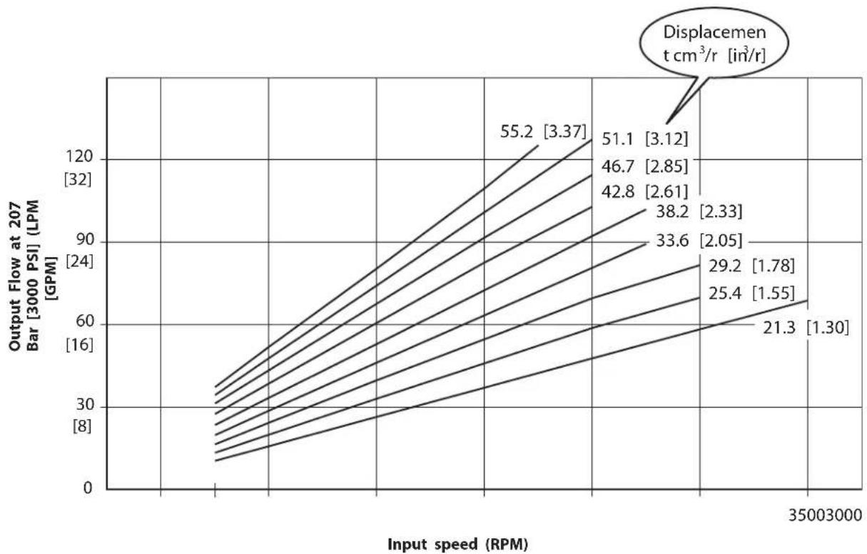
line
| Input speed (RPM) | Output Flow at 207 Bar [3000 PSI] (LPM) [GPM] | | ----------------- | --------------------------------------------- | | 35003000 | 21.3 | | 35003000 | 25.4 | | 35003000 | 29.2 | | 35003000 | 33.6 | | 35003000 | 38.2 | | 35003000 | 42.8 | | 35003000 | 46.7 | | 35003000 | 51.1 | | 35003000 | 55.2 |Input Power vs Speed
line
| Input speed (RPM) | Power at 69 bar [1000 PSI] (kW HP) | | ----------------- | ---------------------------------- | | 35003000 | 55.2 |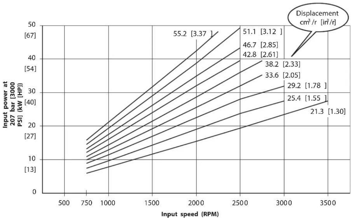
line
| Input speed (RPM) | 207 bar [3000 PSI] (kW HPI) | | ----------------- | ---------------------------- | | 750 | 13 | | 1000 | 10 | | 1500 | 27 | | 2000 | 42 | | 2500 | 54 | | 3000 | 38 | | 3500 | 21.3 |The performance data show in the graphs are representative of this series. Tests were performed per SAE specifications using mineral base oil with a viscosity of 133 SUS at 49^ [120° F].
Series L2 pump
Standard catalog assemblies - dimensions
![Suction port rear porting C L Pressure port rear porting Pressure port side portingt Driveshaft centerline 22.4 [.88] 17.5 [.69] 9.7 [.38] Se e shaft drawing Dia. 101.57 ± 0.03 [3.999 ±.001] 177.8 [7.00] 146 [5.75] 59.9 [2.36] 104.4 [4.11] 2X Dia. 14.5 ± 0.13 [.572 ± .005] 27.7 [1.09] 27.7 [1.09] 81.8 † 75.4 † [2.97] Suction port side porting† Z OUT](/content/2026/04/623181/images/8112886339e41d62eeb6d9135646d641031bec118c8a72a6d0c72a072730c68d.jpg)
Left hand rotation shown
† For split flange porting subtract .8 [.03], available in side porting only
| Model 25500 25501 25502 25503 25504 25505 25506 25507 25508 | |||||||||
| Displacement (cm ^3 /r [in ^3 /r]) | 21.3 [1.30] | 25.4 [1.55] | 29.2 [1.78] | 33.6 [2.05] | 38.2 [2.33] | 42.8 [2.61] | 46.7 [2.85] | 51.1 [3.12] | 55.2 [3.37] |
| Dimension A (mm [in.l]) | 84.8 [3.34] | 88.2 [3.47] | 91.7 [3.61] | 95.1 [3.75] | 98.6 [3.88] | 102.0 [4.02] | 105.3 [4.14] | 109.0 [4.29] | 112.4 |
| [4.43] | |||||||||
| Dimension B (mm [in.j]) | 117.3 [4.62] | 120.8 [4.75] | 124.2 [4.89] | 127.7 [5.03] | 131.1 [5.16] | 134.6 [5.30] | 137.8 [5.42] | 141.5 [5.57] | 145.0 [5.71] |
7/8 inch straight key
Maximum Input Torquett 170
7/8 inch 13 tooth spline
Maximum Input Torquett Nm[1500 lb-in] 209 Nm [1850 lb-in]
7/8 inch 41 tooth spline
Maximum Input Torqueff 316 Nm [2800 lb-in]
![[.97] 4.1 [.16] [.978±.004] 6.30 +0.0 -0.03 [248 +0.0 -0.01] Dia.](/content/2026/04/623181/images/211218f45eb3685abb386fe26771c9e3476cc19ee36328524c828aadd350a922.jpg)
![13 Tooth 16/32 DP 30° Involute Flat root class 1 side fit spline SAE J498b 41.1 [1.62]](/content/2026/04/623181/images/2203519d363843d4abb34cfac72498d40efcdc690f3998f4e32c8d632f7d3f08.jpg)
![41 Tooth 48/96 DP 45° Involute fillet root class 1 side fit spline 13 [.51] Min full spline 24.9 [.98]](/content/2026/04/623181/images/cf9e8329d2a90048ff5c7f3d4e4ca14a30b395dab37c530a8fe8a355ee75a983.jpg)
\* Multiple pump input torque limitations:
The total torque for multiple pump displacements and pressure combinations cannot exceed the maximum input torque rating of the shaft. The proper formula is Pressure times Displacement divided by 6.28.
All dimensions are in mm [in].
| Right hand rotation product no | Left hand rotation product no Shaft | Port location | SAE pressure port size | SAE suction port size | |
| Model 25500 - 21.3 cm3/r [1.30 in3/r] Displacement | |||||
| 25500-RSA 25500-LSA | 13 T Spline Side 1-1/16-12 1-5/8-12 | ||||
| 25500-RSB 25500-LSB | 13 T Spline Rear 1-1/16-12 1-5/8-12 | ||||
| 25500-RSC 25500-LSC | 7/8 Keyed | Side 1-1/16-12 1-5/8-12 | |||
| 25500-RSD | 25500-LSD | 7/8 Keyed | Rear | 1-1/16-12 | 1-5/8-12 |
| 25500-RSE | 25500-LSE | 13 T Spline | Side | 3/4 Split Flange | 1-1/4 Split Flange |
| 25500-RSF | 25500-LSF | 7/8 Keyed | Side | 3/4 Split Flange | 1-1/4 Split Flange |
| Model 25501 - 25.4 cm3/r [1.55 In3/r] Displacement | |||||
| 25501-RSA 25501-LSA | 13 T Spline Side 1-1/16-12 1-5/8-12 | ||||
| 25501-RSB | 25501-LSB 13 T Spline Rear 1-1/16-12 1-5/8-12 | ||||
| 25501-RSC | 25501-LSC 7/8 Keyed | Side 1-1/16-12 1-5/8-12 | |||
| 25501-RSD | 25501-LSD | 7/8 Keyed | Rear | 1-1/16-12 | 1-5/8-12 |
| 25501-RSE | 25501-LSE | 13 T Spline | Side | 3/4 Split Flange | 1-1/4 Split Flange |
| 25501-RSF | 25501-LSF | 7/8 Keyed | Side | 3/4 Split Flange | 1-1/4 Split Flange |
| Model 25502 - 29.2 cm3/r [1.78 in3/r] Displacement | |||||
| 25502-RSA 25502-LSA | 13 T Spline Side 1-1/16-12 1-5/8-12 | ||||
| 25502-RSB | 25502-LSB 13 T Spline Rear 1-1/16-12 1-5/8-12 | ||||
| 25502-RSC 25502-LSC | 7/8 Keyed | Side 1-1/16-12 1-5/8-12 | |||
| 25502-RSD 25502-LSD | 7/8 Keyed | Rear 1-1/16-12 1-5/8-12 | |||
| 25502-RSE | 25502-LSE | 13 T Spline | Side | 3/4 Split Flange | 1-1/4 Split Flange |
| 25502-RSF | 25502-LSF | 7/8 Keyed | Side | 3/4 Split Flange | 1-1/4 Split Flange |
| Model 25503 - 33.6 cm3/r [2.05 In3/r] Displacement | |||||
| 25503-RSA 25503-LSA | 13 T Spline Side 1-1/16-12 1-5/8-12 | ||||
| 25503-RSB 25503-LSB | 13 T Spline Rear 1-1/16-12 1-5/8-12 | ||||
| 25503-RSC 25503-LSC | 7/8 Keyed | Side 1-1/16-12 1-5/8-12 | |||
| 25503-RSD | 25503-LSD | 7/8 Keyed | Rear | 1-1/16-12 | 1-5/8-12 |
| 25503-RSE | 25503-LSE | 13 T Spline | Side | 3/4 Split Flange | 1-1/4 Split Flange |
| 25503-RSF | 25503-LSF | 7/8 Keyed | Side | 3/4 Split Flange | 1-1/4 Split Flange |
| Model 25504 - 38.2 cm3/r [2.33 in3/r] Displacement | |||||
| 25504-RSA 25504-LSA | 13 T Spline Side 1-1/16-12 1-5/8-12 | ||||
| 25504-RSB 25504-LSB | 13 T Spline Rear 1-1/16-12 1-5/8-12 | ||||
| 25504-RSC 25504-LSC | 7/8 Keyed | Side 1-1/16-12 1-5/8-12 | |||
| 25504-RSD | 25504-LSD | 7/8 Keyed | Rear | 1-1/16-12 | 1-5/8-12 |
| 25504-RSE | 25504-LSE | 13 T Spline | Side | 3/4 Split Flange | 1-1/4 Split Flange |
| 25504-RSF | 25504-LSF | 7/8 Keyed | Side | 3/4 Split Flange | 1-1/4 Split Flange |
| Model 25505 - 42.8 cm3/r [2.61 In3/r] Displacement | |||||
| 25505-RSA 25505-LSA | 13 T Spline Side 1-1/16-12 1-5/8-12 | ||||
| 25505-RSB 25505-LSB | 13 T Spline Rear 1-1/16-12 1-5/8-12 | ||||
| 25505-RSC 25505-LSC | 7/8 Keyed | Side 1-1/16-12 1-5/8-12 | |||
| 25505-RSD | 25505-LSD | 7/8 Keyed | Rear | 1-1/16-12 | 1-5/8-12 |
| 25505-RSE | 25505-LSE | 13 T Spline | Side | 3/4 Split Flange | 1-1/4 Split Flange |
| 25505-RSF | 25505-LSF | 7/8 Keyed | Side | 3/4 Split Flange | 1-1/4 Split Flange |
Series L2 pump Order numbers
| Right hand rotation product | def. hold | ||||
| rotationproduct no Shaft | Portlocation | SAE pressureport size | SAE suctionport size | ||
| Model 25506 - 46.7 cm3/r [2.85 in3/r] Displacement | |||||
| 25506-RSA | 25506-LSA | 13 T Spline Side 1-1/16-12 1-5/8-12 | |||
| 25506-RSB | 25506-LSB 13 T Spline Rear 1-1/16-12 1-5/8-12 | ||||
| 25506-RSC | 25506-LSC 7/8 Keyed | Side 1-1/16-12 1-5/8-12 | |||
| 25506-RSD | 25506-LSD | 7/8 Keyed | Rear | 1-1/16-12 | 1-5/8-12 |
| 25506-RSE | 25506-LSE | 13 T Spline | Side | 3/4 Split Flange | 1-1/4 Split Flange |
| 25506-RSF | 25506-LSF | 7/8 Keyed | Side | 3/4 Split Flange | 1-1/4 Split Flange |
| Model 25507 - 51.1 cm3/r [3.12 In3/r] Displacement | |||||
| 25507-RSA | 25507-LSA | 13 T Spline Side 1-1/16-12 1-5/8-12 | |||
| 25507-RSB | 25507-LSB 13 T Spline Rear 1-1/16-12 1-5/8-12 | ||||
| 25507-RSC | 25507-LSC 7/8 Keyed | Side 1-1/16-12 1-5/8-12 | |||
| 25507-RSD | 25507-LSD 7/8 Keyed | Rear | 1-1/16-12 1-5/8-12 | ||
| 25507-RSE | 25507-LSE | 13 T Spline | Side | 3/4 Split Flange | 1-1/4 Split Flange |
| 25507-RSF | 25507-LSF | 7/8 Keyed | Side | 3/4 Split Flange | 1-1/4 Split Flange |
| Model 25508 - 55.2 cm3/r [3.37 in3/r] Displacement | |||||
| 25508-RSA | 25508-LSA | 13 T Spline Side 1-1/16-12 1-5/8-12 | |||
| 25508-RSB | 25508-LSB 13 T Spline Rear 1-1/16-12 1-5/8-12 | ||||
| 25508-RSC | 25508-LSC 7/8 Keyed | Side 1-1/16-12 1-5/8-12 | |||
| 25508-RSD | 25508-LSD | 7/8 Keyed | Rear | 1-1/16-12 | 1-5/8-12 |
| 25508-RSE | 25508-LSE | 13 T Spline | Side | 3/4 Split Flange | 1-1/4 Split Flange |
| 25508-RSF | 25508-LSF | 7/8 Keyed | Side | 3/4 Split Flange | 1-1/4 Split Flange |
Series L2 pump
Optional configurations
The L2 Series gear pump components can be assembled into many optional configurations. The versatile design allows you to assemble a pump to meet your specific needs.
Model codes for single and multiple pumps along with the component part dimension drawings are given on the following pages.
Single gear pump with Double gear pump with spilt-flange ports commo
natural_image
Technical line drawing of a mechanical component with mounting holes and shafts (no text or symbols)common suction port
natural_image
Technical line drawing of a mechanical component with no visible text or symbolsTriple gear pump with two suction ports
natural_image
Technical line drawing of a mechanical component with no visible text or symbolsSingle gear pump with Double gear pump with Triple gear pump with flow divider flow divider
natural_image
Technical line drawing of a mechanical component with no visible text or symbols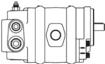
natural_image
Technical line drawing of a mechanical device with no visible text or symbolsflow divider
natural_image
Technical line drawing of a mechanical component with no visible text or symbolsSingle gear pump with SAE A flange auxiliary mount
natural_image
Technical line drawing of a mechanical assembly (no text or symbols)Double gear pump with common suction port and SAE A flange auxiliary mount
natural_image
Technical line drawing of a mechanical assembly (no text or symbols)Triple gear pump with two suction ports and SAE A Flange auxiliary mount
natural_image
Technical line drawing of a mechanical assembly (no text or symbols)Series L2 pump
Component parts - dimensions
Front plate
SAE 2 Bolt B Mount .Used on all Standard Catalog Assemblies .
![17.5 [.69] 9.7 [.38] Dia. 101.57±0.03 [3.999±.001] 40.1 [1.58] 146 [5.75] 177.8 [7.00] 57.2 [2.36] 2X Dia. 14.5±0.13 [.572±.005] C L 99.5 [3.92]](/content/2026/04/623181/images/3756fe4c5960c3815985c626fc1f2a0d4eb417c00d8c8384fdfe8dd58615470a.jpg)
Body
Used on Single and Multiple Pumps
Displacement Dimension A
| cm^3/r in^3/j mm in. . | |
| 21.3 [1.3 0 | 19.8 [ , 7 8 ] |
| 25.4 [1.55] | 23.1 [ , 9 1 ] |
| 29.2 [1.78] | 26.7 [1.05] |
| 33.6 [2.05] | 30.0 [1.18] |
| 38.2 [2.33] | 1.32 [33.5] |
| 42.8 [2.61] | ] |
| 46.7 [2.85] | 37.1 [1.46] |
| 51.1 [3.12] | 1.59 [40.4] |
| 55.2 [3.37] | ] |
| 43.9 [1.73] | |
Backplate
Used on Single and Multiple Pumps
![Suctio n port rear porting N Suctio n port side porting† 27. 7 [1.09] 81. 8⁺ [3.22] C L 27. 7 [1.09] 75. 4⁺ [2.97] OUT Pressure port rear porting Pressure port side portingt Drive shaft t C L 22. 4 [.88] 25. 1 [.99] 57. 7 [2.27]](/content/2026/04/623181/images/7d99b55f2a11802a6f9c2f0e2589251c05c7a197eca91fa848a916fdfbfda158.jpg)
Left hand rotation shown
† For split flange porting subtract .8 [.03], available in side porting only
Flow divider backplate
Used on single and multiple pumps
![76.5 [3.01] Max. 21.3 [.84] 22.4 [.88] Suction port side porting Suction port rear portin g 101.1 [3.98] 1.5 [.06 ] Priority pressure port rear portin g 1.5 [.06 ] 46.2 [1.82] Secondary pressure port rear porting 29.5 [1.16] 25.4 [1.00] 65 [2.56] 68.3 [2.69] C L 52.1 [2.05] 80.3 [3.16 ] 93.5 [3.68] Optional hex plug (no relief valve) Priority pressure port sid e porting Drive shaft C L 80.0 [3.15] Secondary pressure e port sid e porting Top View](/content/2026/04/623181/images/3288223b9a9b1c03e93315348981dcafc8b202ab50166cbef982a6ba5c868e52.jpg)
Left hand rotation shown
Series L2 pump
Component parts - dimensions
Tandem backplate with SAE 2 bolt a flange
Used on single and multiple pumps
![Spacer Used with 11 tooth spline output shaft See model code for output shaft options 106.4 [4.19] 2X 3/8-16 UNC-2B 23.8 [.94] Min. Full thread depth Pressure port† Drive shaft C L 22.4 [.88] Suction port † 86.9 † [3.42] 86.9 † [3.42] 57.9 [2.28] 106. 4 36.8 [1.45] [4.19] 24.9 [.98] 43.2 [1.70] ]](/content/2026/04/623181/images/486c0ea16e63cd1b0e98052a80c7640197aa8d22c7a97387f20c6cf715af0290.jpg)
Right hand rotation shown
† For split flange porting subtract .8 [.03]
Adaptor plate
Used on multiple pumps
![Pressure port † 76.2 [3.00] C 82.6 [3.25] L Drive e shaft C L 22.4 [.88] Suction port † 30.2 [1.19] 60.5 [2.38]](/content/2026/04/623181/images/7c67db6d6052938a0454a227c27fbaa518d25ca077c8e2dcf72751f6d6d6a421.jpg)
Right hand rotation shown
† For split flange porting subtract .8 [.03]
Series L2 Pump Model code - single
L2 gear pumps can be ordered by using the following Model Code.
A twenty-three digit coding system has been designed to identify all of the features available on L2 single gear pumps. The characters and their relative positions within the code identify specific features.
Use the Model Code Matrix as an aid when assembling the model code for the pump with the features you desire. It may be helpful to photocopy the matrix and write the numbers and letters into the boxes as you select features.
All twenty-three digits of the code must be submitted when ordering. The seven zeros at the end of the model code are for factory use, be sure to include them when ordering.
| ABF | * | * | ** | ** | ** | ** | ** | ** | ** | * | 0 | 00 | 00 | 0 | 0 |
| 1 | 2 | 3 | 4 | 5 | 6 | 7 | 8 | 9 | 10 | 11 | 12 | 13 | 14 | 15 |
1 2 3 L2 Series
| ABF Gear Pump - Single Unit | ||
| 4 | Unit type | |
| A Plain | ||
| B Flow Divider with/without Relief Valve (Pos 14-15) | ||
| 5 | Input rotation (viewed from input shaft end) | |
| L Left-hand Rotation CCW | ||
| R Right-hand Rotation CW | ||
| 6 7 | Displacement ( cm^3/r [in ^3 /r]) | |
| 0 21.3 [1. 30] | ||
| 1 25.4 [1.55] | ||
| 2 29.2 [1.78] | ||
| 3 33.6 [2 .05] | ||
| 4 38.2 [2.33] | ||
| 5 42.8 [2.61] | ||
| 6 46.7 [2.85] | ||
| 7 51.1 [3 .12] | ||
| 8 55. 2 [3 .37] | ||
| 8 9 | Input shaft | |
| AA 7/8 Inch Dia . 13 Tooth Spline 16/32 Pitch Shaft Extension 41 .1 [1.62] | ||
| AB 7/8 Inch Dia . Straight Keyed, Keyway 6 .4 X 25.4 [.25 X 1 .00] Shaft Extension 41 .1 [1.62] | ||
| AD 7/8 Inch Dia . 41 Tooth Spline 48/96 Pitch Shaft Extension 24 .9 [.98] | ||
10 11 Ports, sizes and location- backplate
| 1 | 1 5/8-12 Suction; 1 1/16- 12 Pressure SAE Straight Thread O-ring Ports - Side |
| 2 | 1 5/8-12 Suction; 1 1/16- 12 Pressure SAE Straight Thread O-ring Ports - Rear |
| 3 | 1 1/4 Suction; 3/4 Pressure Split Flange Ports - Side |
| 4 | 1 5/8-12 Suction; 7/8-14 Priority Pressure; 1 1/16-12 Secondary Pressure SAE Straight Thread O-ring Ports - Side |
| 05 | 1 5/8-12 Suction; 7/8-14 Priority Pressure; 1 1/16-12 Secondary Pressure SAE Straight Thread O-ring Ports - Rear |
12 13 Priority flow divider setting (LPM [GPM])
| 00 | No Flow Setting |
| AA | 3.8 [1.00] |
| AB | 5.7 [1. 50] |
| AC | 7.6 [2.00] |
| AD | 9.5 [2.50] |
| AE | 11.4 [3 .00] |
| AF | 13.3 [3 .50] |
| AG | 15.1 [4 .00] |
| AH | 17.0 [4 .50] |
| AJ | 18.9 [5 .00] |
| AK | 20.8 [5 .50] |
| AL | 22.7 [6 .00] |
| AN | 26.5 [7.00] |
| AP | 30.3 [8 .00] |
| AR | 34.1 [9 .00] |
| AS | 37.8 [10 .00] |
Series L2 Pump Model code - single
| ABF | * | * | ** | ** | ** | ** | ** | ** | ** | * | 0 | 00 | 00 | 0 | 0 |
| 1 | 2 | 3 | 4 | 5 | 6 | 7 | 8 | 9 | 10 | 11 | 12 | 13 | 14 | 15 |
14 15 Relief valve full flow setting (bar [PSI])
00 No Relief Valve Setting
AA 34.5 [500]
AB 51.7 [750]
AC 68.9 [1000]
AD 86.2 [1250]
AE 103.4 [1500]
AF 120.6 [1750]
AG 137.9 [2000]
AH 155.1 [2250]
AJ 172.4 [2500]
AK 189 .6 [2750]
AL 206 .8 [3000]
| 16 | Auxiliary rear mount |
| 0 None | |
| B 2 Bolt A SAE Flange Series 82-2 Output Shaft Accepts 9 Tooth Spline 16/32 Pitch, Shaft Extension 31 .8 [1.25] | |
| C 2 Bolt A SAE Flange Series 82-2, With 11 Tooth 16/32 Pitch External Spline Output Shaft, 17 .5 [.69] Minimum Full Spline, Requires Spacer and Coupler to Accept 31.8 [1. 25] Mating Shaft Extension |
| 17 | Test data |
| 0 Generic | |
| A Unit Specific (required for flow divider and relief valve options.) |
| 18 | 19 | Special features |
| 00 No Special Features | ||
| AB Viton Shaft Seal | ||
| 20 | 21 | Paint |
| 00 None | ||
| 0A Red Primer | ||
| 0B Black | ||
| 22 | Identification | |
| 0 Standard | ||
| 23 | Design code | |
| A A |
Series L2 pump
Model code - multiple
Multiple L2 gear pumps can be ordered by using the following Model Code.
A twenty-eight digit coding system has been designed to identify all of the features available on L2 double and triple gear pumps. The characters and their relative positions within the code identify specific features.
Use the Model Code Matrix as an aid when assembling the model code for the pump with the features you desire. It may be helpful to photocopy the matrix and write the numbers and letters into the boxes as you select features.
All twenty-eight digits of the code must be submitted when ordering. The six zeros at the end of the model code are for factory use, be sure to include them when ordering.

1 2 3 L2 Series
ABG Gear Pump - Multiple Unit
4 Unit type
A Plain
B Flow Divider with/without Relief Valve (Pos 20-21)
5 Input rotation (viewed from input shaft end)
L Left-hand Rotation CCW
R Right-hand Rotation CW
6 7 Displacement (cm³/r [in³/r])
0 21.3 [1.30]
1 25.4 [1.55]
2 29.2 [1.78]
3 33.6 [2 .05]
4 38.2 [2 . 33]
5 42.8 [2 .61]
6 46.7 [2 .85]
7 51.1 [3 .12]
8 55.2 [3 .37]
8 9 Displacement of center section (cm³/r [in³/r])
0 21.3 [1.30]
1 25.4 [1.55]
2 29.2 [1.78]
3 33.6 [2 .05]
4 38.2 [2 . 33]
5 42.8 [2 .61]
6 46.7 [2 .85]
7 51.1 [3 .12]
8 55.2 [3 .37]
99 No Center Displacement
10 11 Displacement of rear section (cm³/r [in³/r])
0 21.3 [1.30]
1 25.4 [1.55]
2 29.2 [1.78]
3 33.6 [2 .05]
4 38.2 [2 . 33]
5 42.8 [2 .61]
6 46.7 [2 .85]
7 51.1 [3 .12]
8 55.2 [3 .37]
12 13 Input shaft
AA 7/8 Inch Dia. 13 Tooth Spline 16/32 Pitch Shaft Extension 41 .1 [1.62]
AB 7/8 Inch Dia. Straight Keyed, Keyway 6 .4 X 25.4 [.25 X 1 .00] Shaft Extension 41 .1 [1.62]
AE 7/8 Inch Dia. 41 Tooth Spline 48/96 Pitch Shaft Extension 24 .9 [.98]
14 Front adaptor ports
1 5/8-12 Suction; 1 1/16-12 Pressure - SAE Straight Thread O-ring Ports
3 1 1/4 Suction; 3/4 Pressure Split Flange Ports, Common Suction
Series L2 pump Model code - multiple
| ABG | * | * | ** | ** | ** | ** | * | * | ** | ** | ** | * | 00 | 00 | 0 | A |
| 1 | 2 | 3 | 4 | 5 | 6 | 7 | 8 | 9 | 10 | 11 | 12 | 13 | 14 | 15 | 16 |
15 Rear adaptor ports (triple pumps)
0 No Rear Adaptor
1 1 5/8-12 Suction; 1 1/16- 12 Pressure - SAE Straight Thread O-ring Ports
3 1 1/4 Suction; 3/4 Pressure Split Flange Ports, Common Suction
16 17 Ports, sizes and location- backplate
03 1 5/8-12 Suction; 1 1/16- 12 Pressure SAE Straight Thread O-ring Ports - Rear
05 1 5/8-12 Suction; 7/8-14 Priority Pressure; 1 1/16-12 Secondary Pressure SAE Straight Thread O-ring Ports - Side
06 1 5/8-12 Suction; 7/8-14 Priority Pressure; 1 1/16-12 Secondary Pressure SAE Straight Thread O-ring Ports - Rear
7 1 5/8-12 Suction (Plugged); 1 1/16-12 Pressure SAE Straight Thread O-ring Ports - Rear
8 1 1/4 Suction; 3/4 Pressure Split Flange Ports - Side
18 19 Priority flow divider setting (LPM [GPM])
00 No Flow Setting
AA 3.8 [1.00]
AB 5.7 [1.50]
AC 7.6 [2 .00]
AD 9.5 [2.50]
AE 11.4 [3.00]
AF 13.3 [3 .50]
AG 15.1 [4 .00]
AH 17.0 [4 .50]
AJ 18.9 [5 .00]
AK 20.8 [5 .50]
AL 22.7 [6 .00]
AN 26.5 [7.00]
AP 30.3 [8 .00]
AR 34.1 [9.00]
AS 37.8 [10 .00]
20 21 Relief valve full flow setting (bar [PSI])
00 No Relief Valve Setting
AA 34.5 [500]
AB 51.7 [750]
AC 68.9 [1000]
AD 86.2 [1250]
AE 103.4 [1500]
AF 120.6 [1750]
AG 137.9 [2000]
AH 155.1 [2250]
AJ 172.4 [2500]
AK 189.6 [2750]
AL 206.8 [3000]
22 Test data
0 Generic
A Unit Specific (required for flow divider and relief valve options.)
23 24 Special features
00 No Special Features
AA Viton Shaft Seal
AE 2 Bolt A SAE Flange Series 82-2 Output Shaft Accepts 9 Tooth Spline 16/32 Pitch, Shaft Extension 31 .8 [1.25]
AF 2 Bolt A SAE Flange Series 82-2, With 11 Tooth 16/32 Pitch External Spline Output Shaft, 17 .5 [.69] Minimum Full Spline, Requires Spacer and Coupler to Accept 31.8 [1.25] Mating Shaft Extension
25 26 Paint
00 None
OA Red Primer
OB Black
27 Identification
0 Standard
28 Design code
A A
Notes
Products we offer:
- Cartridge valves
• DCV directional control valves
• Electric converters
Electric machines
Electric motors - Gear motors
- Gear pumps
• Hydraulic integrated circuits (HICs) - Hydrostatic motors
• Hydrostatic pumps - Orbital motors
- PLUS+1* controllers
- PLUS+1* displays
• PLUS+1*joysticks and pedals
• PLUS+1* operator interfaces - PLUS+1* sensors
- PLUS+1*software
• PLUS+1* software services, support and training
• Position controls and sensors
• PVG proportional valves
• Steering components and systems - Telematics
Danfoss Power Solutions is a global manufacturer and supplier of high-quality hydraulic and electric components. We specialize in providing state-of-the-art technology and solutions that excel in the harsh operating conditions of the mobile off-highway market as well as the marine sector. Building on our extensive applications expertise, we work closely with you to ensure exceptional performance for a broad range of applications. We help you and other customers around the world speed up system development, reduce costs and bring vehicles and vessels to market faster.
Danfoss Power Solutions – your strongest partner in mobile hydraulics and mobile electrification.
Go to www.danfoss.com for further product information.
We offer you expert worldwide support for ensuring the best possible solutions for outstanding performance. And with an extensive network of Global Service Partners, we also provide you with comprehensive global service for all of our components.
Local address:
Hydro-Gear
www.hydro-gear.com
Daikin-Sauer-Danfoss
www.daikin-sauer-danfoss.com
Danfoss
Power Solutions (US) Company
2800 East 13th Street
Ames, IA 50010, USA
D-24539 Neumünster, Germany
Phone: +49 4321 871 0
Danfoss
Power Solutions ApS
Nordborgvej 81
DK-6430 Nordborg, Denmark
Phone: +45 7488 2222
Danfoss
Power Solutions Trading
(Shanghai) Co., Ltd.
Building #22, No. 1000 Jin Hai Rd
Jin Qiao, Pudong New District
Shanghai, China 201206
Phone: +86 21 2080 6201
Danfoss can accept no responsibility for possible errors in catalogues, brochures and other printed material. Danfoss reserves the right to alter its products without notice. This also applies to products already on order provided that such alterations can be made without subsequent changes being necessary in specifications already agreed.
All trademarks in this material are property of the respective companies. Danfoss and the Danfoss logotype are trademarks of Danfoss A/S. All rights reserved.