
ProLITE 5.0 DSP - Receiver PEAVEY - Free user manual and instructions
Find the device manual for free ProLITE 5.0 DSP PEAVEY in PDF.

| Product Type | Professional power amplifier with DSP |
| Brand | Peavey |
| Model | ProLITE 5.0 DSP |
| Rated power (2 ohms) | 3300 W (burst) / 2600 W (THD 1%) per channel |
| Rated power (4 ohms) | 2000 W (burst) / 1700 W (THD 1%) per channel |
| Rated power (8 ohms) | 1175 W (burst) / 1000 W (THD 1%) per channel |
| Minimum impedance | 2 ohms |
| Frequency response | 20 Hz - 22 kHz (+/- 0.5 dB at 1 W) |
| Voltage gain | x70 (+37 dB) |
| Inputs | Combo XLR / 1/4" (2 channels) |
| Outputs | 2x 1/4" and 1x 2-pin / 4-pin twist locking connector per channel |
| DSP functions | Adjustable high-pass/low-pass filters (Butterworth, Linkwitz-Riley 12/18/24 dB/oct), 5-band parametric EQ, MaxxBass®, Horn EQ, delay up to 125 ms, limiters, 4 memories, password lock |
| Protections | Thermal, DC, subsonic, incorrect loads, under/over voltage, ACL™ (Automatic Clip Limiting) |
| Indicators | Active, Signal, ACL, Temperature, DC (LED per channel) |
| Cooling | 3 variable speed fans |
| Power supply | 120 V / 240 V AC, stable consumption 195 VA (90 W) |
| Dimensions (W x H x D) | 19" x 3.5" x 17.25" (plus 0.75" for handle) |
| Net weight | 6.4 kg (14.2 lb) |
| Gross weight | 8.2 kg (18.0 lb) |
| Construction | 0.062" thick aluminum |
| Maintenance | Wipe with a dry cloth. Do not expose to liquids. Refer all repairs to a certified technician. |
| Safety | Do not open the enclosure, risk of electric shock. Use a grounded outlet. Follow ventilation instructions (30 cm clearance). |
Frequently Asked Questions - ProLITE 5.0 DSP PEAVEY
User questions about ProLITE 5.0 DSP PEAVEY
0 question about this device. Answer the ones you know or ask your own.
Ask a new question about this device
Download the instructions for your Receiver in PDF format for free! Find your manual ProLITE 5.0 DSP - PEAVEY and take your electronic device back in hand. On this page are published all the documents necessary for the use of your device. ProLITE 5.0 DSP by PEAVEY.
USER MANUAL ProLITE 5.0 DSP PEAVEY
Pro-LITE® 5.0 / 7.5 DSP
Power Amplifiers
Owner's Manual

CREST AUDIO®

Intended to alert the user to the presence of uninsulated “dangerous voltage” within the product’s enclosure that may be of sufficient magnitude to constitute a risk of electric shock to persons.
Intended to alert the user of the presence of important operating and maintenance (servicing) instructions in the literature accompanying the product.
CAUTION: Risk of electrical shock — DO NOT OPEN!
CAUTION: To reduce the risk of electric shock, do not remove cover. No user serviceable parts inside. Refer servicing to qualified service personnel.
WARNING: To prevent electrical shock or fire hazard, this apparatus should not be exposed to rain or moisture, and objects filled with liquids, such as vases, should not be placed on this apparatus. Before using this apparatus, read the operating guide for further warnings.

Protective earthing terminal. The apparatus should be connected to a mains socket outlet with a protective earthing connection.

IMPORTANT SAFETY INSTRUCTIONS
WARNING: When using electrical products, basic cautions should always be followed, including the following:
- Read these instructions.
- Keep these instructions.
- Heed all warnings.
- Follow all instructions.
- Do not use this apparatus near water.
-
Clean only with a dry cloth.
-
Do not block any of the ventilation openings. Install in accordance with manufacturer's instructions.
-
Do not install near any heat sources such as radiators, heat registers, stoves or other apparatus (including amplifiers) that produce heat.
-
Do not defeat the safety purpose of the polarized or grounding-type plug. A polarized plug has two blades with one wider than the other. A grounding type plug has two blades and a third grounding plug. The wide blade or third prong is provided for your safety. If the provided plug does not fit into your outlet, consult an electrician for replacement of the obsolete outlet.
-
Protect the power cord from being walked on or pinched, particularly at plugs, convenience receptacles, and the point they exit from the apparatus.
-
Only use attachments/accessories provided by the manufacturer.
-
Use only with a cart, stand, tripod, bracket, or table specified by the manufacturer, or sold with the apparatus. When a cart is used, use caution when moving the cart/apparatus combination to avoid injury from tip-over.
-
Unplug this apparatus during lightning storms or when unused for long periods of time.
-
Refer all servicing to qualified service personnel. Servicing is required when the apparatus has been damaged in any way, such as power-supply cord or plug is damaged, liquid has been spilled or objects have fallen into the apparatus, the apparatus has been exposed to rain or moisture, does not operate normally, or has been dropped.
-
Never break off the ground pin. Write for our free booklet "Shock Hazard and Grounding." Connect only to a power supply of the type marked on the unit adjacent to the power supply cord.
-
If this product is to be mounted in an equipment rack, rear support should be provided.
-
Note for UK only: If the colors of the wires in the mains lead of this unit do not correspond with the terminals in your plug, proceed as follows: a) The wire that is colored green and yellow must be connected to the terminal that is marked by the letter E, the earth symbol, colored green or colored green and yellow. b) The wire that is colored blue must be connected to the terminal that is marked with the letter N or the color black. c) The wire that is colored brown must be connected to the terminal that is marked with the letter L or the color red.
-
This electrical apparatus should not be exposed to dripping or splashing and care should be taken not to place objects containing liquids, such as vases, upon the apparatus.
-
The on/off switch in this unit does not break both sides of the primary mains. Hazardous energy can be present inside the chassis when the on/off switch is in the off position. The mains plug or appliance coupler is used as the disconnect device, the disconnect device shall remain readily operable.
-
Exposure to extremely high noise levels may cause a permanent hearing loss. Individuals vary considerably in susceptibility to noise-induced hearing loss, but nearly everyone will lose some hearing if exposed to sufficiently intense noise for a sufficient time. The U.S. Government's Occupational Safety and Health Administration (OSHA) has specified the following permissible noise level exposures:
Duration Per Day In Hours Sound Level dBA, Slow Response
| 8 90 | |
| 6 92 | |
| 4 95 | |
| 3 97 | |
| 2 100 | |
| 1 1/2 102 | |
| 1 105 | |
| 1/2 | 110 |
| 1/4 or less | |
According to OSHA, any exposure in excess of the above permissible limits could result in some hearing loss. Earplugs or protectors to the ear canals or over the ears must be worn when operating this amplification system in order to prevent a permanent hearing loss, if exposure is in excess of the limits as set forth above. To ensure against potentially dangerous exposure to high sound pressure levels, it is recommended that all persons exposed to equipment capable of producing high sound pressure levels such as this amplification system be protected by hearing protectors while this unit is in operation.
SAVE THESE INSTRUCTIONS!
a) The wire that is colored green and yellow must be connected to the terminal that is marked by the letter E, the earth symbol, colored green or colored green and yellow.
b) The wire that is colored blue must be connected to the terminal that is marked with the letter N or the color black.
c) The wire that is colored brown must be connected to the terminal that is marked with the letter L or the color red.
a) The wire that is colored green and yellow must be connected to the terminal that is marked by the letter E , the earth symbol, colored green or colored green and yellow.
b) The wire that is colored blue must be connected to the terminal that is marked with the letter N or the color black.
c) The wire that is colored brown must be connected to the terminal that is marked with the letter L or the color red.
a) The wire that is colored green and yellow must be connected to the terminal that is marked by the letter E, the earth symbol, colored green or colored green and yellow.
b) The wire that is colored blue must be connected to the terminal that is marked with the letter N or the color black.
c) The wire that is colored brown must be connected to the terminal that is marked with the letter L or the color red.
a) The wire that is colored green and yellow must be connected to the terminal that is marked by the letter E, the earth symbol, colored green or colored green and yellow.
b) The wire that is colored blue must be connected to the terminal that is marked with the letter N or the color black.
Logo referenced in Directive 2002/96/EC Annex IV(OJ(L)37/38,13.02.03 and defined in EN 50419: 2005
The bar is the symbol for marking of new waste and is applied only to equipment manufactured after 13 August 2005
Correct Disposal of this product. This marking indicates that this product should not be disposed with other house hold wastes throughout the EU. To prevent possible harm to the environment or human health from uncontrolled waste disposal, recycle it responsibly to promote the sustainable reuse of material resources. To return your used device, please use the return and collection systems, or contact the retailer where the product was purchased. They can take this product for environmental safe recycling.

FCC Compliancy Statement
This device complies with Part 15 of the FCC rules. Operation is subject to the following two conditions: (1) this device may not cause harmful interference, and (2) this device must accept any interference received, that may cause undesired operation.
Warning: Changes or modifications to the equipment not approved by Peavey Electronics Corp. can void the user's authority to use the equipment.
Note - This equipment has been tested and found to comply with the limits for a Class B digital device, pursuant to Part 15 of the FCC Rules. These limits are designed to provide reasonable protection against harmful interference in a residential installation. This equipment generates, uses and can radiate radio frequency energy and, if not installed and used in accordance with the instructions, may cause harmful interference to radio communications. However, there is no guarantee that interference will not occur in a particular installation. If this equipment does cause harmful interference to radio or television reception, which can be determined by turning the equipment off and on, the user is encouraged to try and correct the interference by one or more of the following measures.
- Reorient or relocate the receiving antenna.
- Increase the separation between the equipment and receiver.
- Connect the equipment into an outlet on a circuit different from that to which the receiver is connected.
- Consult the dealer or an experienced radio/TV technician for help.
ENGLISH
Pro-LITE® 5.0 / 7.5
Power Amplifiers
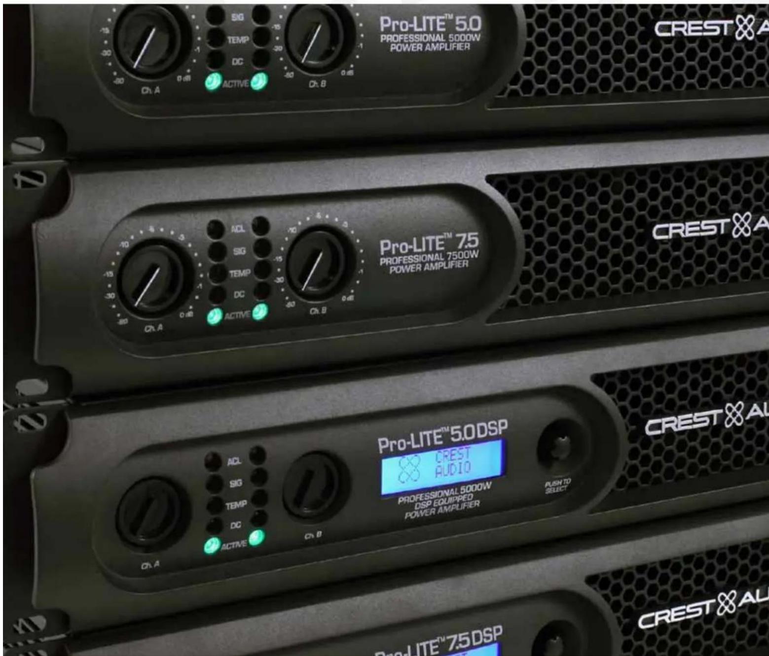
Congratulations on your purchase of the Crest Pro-LITE power amplifier! Designed for years of reliable, flawless operation under rigorous use, the groundbreaking Pro-LITE TM series utilizes an advanced design that dramatically reduces weight, while increasing output power, reliability and thermal efficiency. Pro-LITE Series amplifiers are also designed with a resonant switch-mode power supply and a highspeed class D topology, that yields the highest audio resolution and efficiency available. This revolutionary amplifier offers the sonic superiority and unsurpassed reliability for which Crest is famous, in an extremely efficient and lightweight design. Advanced technology and extensive protection circuitry allow operation with greater efficiency into difficult loads and power conditions. In other words, you get an amazingly powerful and efficient amplifier that won't break your budget or your back! The ACL TM (Automatic Clip Limiting) circuitry ensures trouble-free operation into loads as low as 2 ohms. ACL TM protects drivers and ensures that sonic integrity is maintained, even in extreme overload conditions. The Pro-LITE's high-efficiency design allows the amplifier to operate at very low temperatures, and does not require massive heat sinks to cool. For your safety, read the important precautions section, as well as input, output and power connection instructions.
Although the Pro-LITE ® amplifier is simple to operate and housed in an ultra-strong, ultra-lightweight chassis, improper use can be dangerous. This amplifier is very high-powered and can put out high voltages and sizable currents at frequencies up to 30 kHz. Always use safe operating techniques when operating this amplifier.
Before you apply power to your amplifier, it is very important to ensure that the product has the proper AC line voltage supplied. You can find the proper voltage for your amp printed next to the IEC line (power) cord on the rear panel of the unit. Each product feature is numbered. Refer to the front-panel diagram in this manual to locate the particular features next to its number.

Please read this guide carefully to ensure your personal safety as well as the safety of your amplifier.

VENTILATION: For proper ventilation, allow 12" clearance from nearest combustible surface. Make sure that vents are not blocked and air can flow freely through the unit.
Pro-LITE® Features:
• 2 channel independent crossovers
- ACL TM protection
• Revolutionary class D topology
• Detented input controls
• Combination XLR 1/4" inputs
• 4 pole twist lock output connectors
- Ultra-light weight
- Individual signal pass 1/4" jacks on each channel
- LED illuminated
- Standby, LED power present indication

WARNING: Changes or modifications to this unit not expressly approved by the party responsible for compliance could void the user's authority to operate the equipment.
NOTE: This equipment has been tested and found to comply with the limits for a Class A digital device, pursuant to Part 15 of the FCC Rules. These limits are designed to provide reasonable protection against harmful interference in a residential installation. This equipment generates, uses and can radiate radio frequency energy and if not installed and used in accordance with the instructions may cause harmful interference to radio communications.
However, there is no guarantee that interference will not occur in a particular installation. If this equipment does cause harmful interference to radio or television reception, which can be determined by turning the equipment off and on, the user is encouraged to try to correct the interference by one or more of the following measures:
- Reorient or relocate the receiving antenna.
- Increase the separation between the equipment and receiver.
- Connect the equipment into an outlet on a circuit different from that to which the receiver is connected.
- Consult the dealer or and experienced radio/TV technician for help.
Front Panel
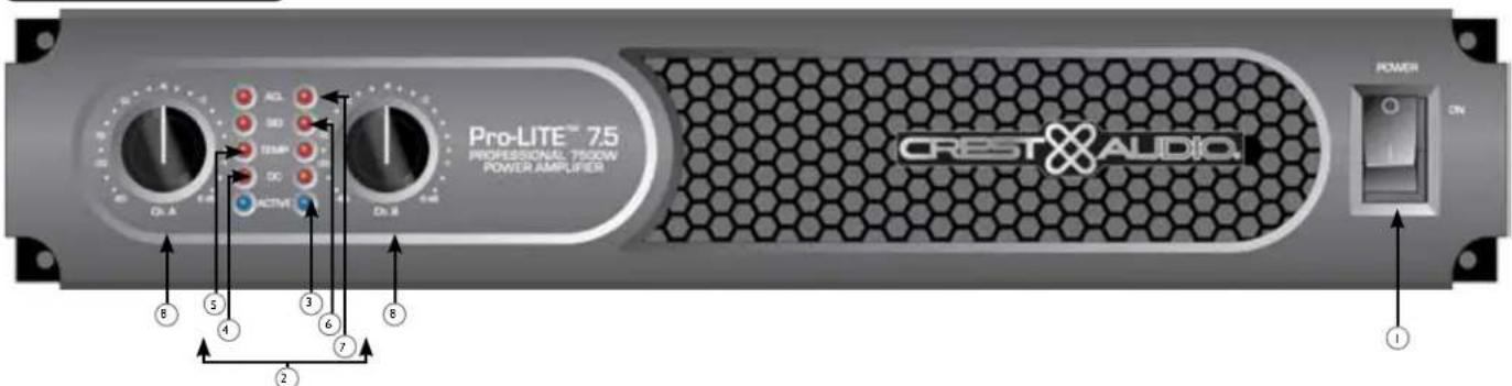
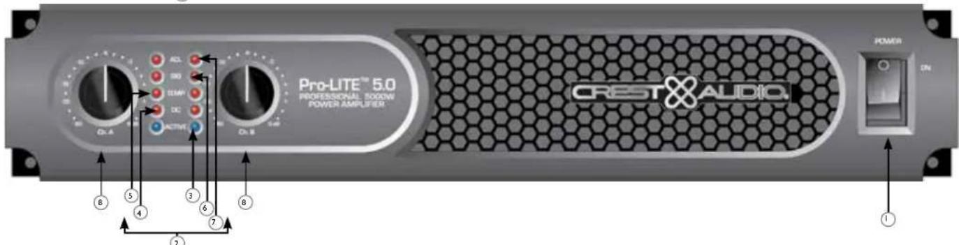
① AC POWER SWITCH
This switch sends power to the amplifier.
2 INDICATORS
The Pro-LITE® amplifiers feature five front-panel LED indicators per channel: ACTIVE, DC, TEMP, SIGNAL and ACL These LED indicators inform the user of each channel's operating status and warn of possible abnormal conditions.
3 ACTIVE LED
The Active LED indicates that the channel is operational. It lights under normal operation and remains on even when the channel is in ACL ™ gain reduction. If the Active LED goes off, there is no signal at the output connectors.
4 DC LED
In the event of abnormal operating conditions, the Pro-LITE ® has built-in amplifier protection. Under conditions that would normally damage the power amplifier, the DC LED will illuminate and the amp will automatically attempt to restart to correct the condition. If the amplifier does not return to normal operating status, contact your local authorized service center:
5 TEMP LED
In the unlikely event of an unstable thermal condition, amplifier protection will be activated and will shut down the offending channel. The Temp LED will remain illuminated until safe operating temperatures have returned.
6 SIGNAL LED
This LED lights when its channel produces an output signal of about 4 volts RMS or more (0.1 volt or more at the input, with 0 dB attenuation and standard x40 voltage gain). This signal indicates whether a signal is reaching and being amplified by the amplifier.
⑦ ACL™ (Automatic Clip Limiting) LED
A channel's ACL™ LED will light at the onset of clipping. If the LEDs are flashing quickly and intermittently, the channel is just at the clip threshold. A steady, bright glow means the amp is clip limiting or preventing severely clipped waveforms from reaching the loudspeakers. During initial power-up the ACL' LED will light.
⑧ INPUT ATTENUATORS
Whenever possible, set the attenuators fully clockwise to maintain optimum system headroom. The input attenuator controls, located at the front panel (one for channel A, one for channel B), adjust gain for their respective amplifier channels in all modes. See the specifications at the end of this manual for standard voltage gain and input sensitivity information.

AC POWER INLET:
This is the receptacle for an IEC line cord, which provides AC power to the unit. Connect the line cord to this connector to provide power to the unit. Damage to the equipment may result if improper line voltage is used. (See line voltage marking on unit). The 120VAC Pro-LITE® 7.5 gets a power cord retaining clamp.
Never break off the ground pin on any equipment. It is provided for your safety. If the outlet used does not have a ground pin, a suitable grounding adapter should be used and the third wire should be grounded properly. To prevent the risk of shock or fire hazard, always make sure that the amplifier and all associated equipment is properly grounded.
NOTE: FOR U.K. ONLY
As the colors of the wires in the mains lead of this apparatus may not correspond with the colored markings identifying the terminals in your plug, proceed as follows: (1) The wire which is colored green and yellow must be connected to the terminal which is marked by the letter E, or by the Earth symbol, or colored green or green and yellow. (2) The wire which is colored blue must be connected to the terminal which is marked with the letter N, or the color black. (3) The wire which is colored brown must be connected to the terminal which is marked with the letter L, or the color red.

CONNECTING OUTPUTS
All models have one combination 4 pole twist lock output connector per channel. Channel A output allows for CHA 1+ Pos / 1- Neg and Channel B 2+ Pos / 2- Neg to use a single 4 conductor speaker cable.

CONNECTING INPUTS
Input connections are made via the 3-pin XLR (pin 2+) or 6.3 mm plug combination connectors on the rear panel of the amplifier. The inputs are actively balanced.

THRU/OUT JACKS
This 1/4" jack supplies parallel output signals from the associated channel for patching to this amplifier and/or additional power amplifier inputs.

CHANNEL MODE SWITCH
HIGH PASS
This position is used to activate the HIGH PASS filter for the corresponding channel. This filter will limit the frequencies sent to the associated amplifier channel to frequencies above 100 Hz. In situations where separate subwoofer cabinets are being used, this position would indicate connecting the mid-high frequency speaker cabinet to the channel associated with the HIGH PASS switch.
FULL RANGE
As the name implies, the Full Range position on this switch allows all frequencies to pass to the amplifier. Normally used when connecting a full range speaker enclosure to the amplifier's output.
SUBWOOFER
This position is used to activate the LOW PASS filter for the corresponding channel. This filter will limit the frequencies sent to the associated amplifier channel to frequencies below 100 Hz. In situations where separate subwoofer cabinets are being used, this position would indicate connecting the subwoofer speaker cabinet to the channel associated with the Subwoofer switch.
ENGLISH
Pro-LITE® DSP 5.0 / 7.5
Power Amplifiers
As the name implies, the Pro-LITE® DSP all include advanced digital signal processing. The DSP was designed to be incredibly effective, yet extremely easy to use. Using unique and revolutionary advanced bass enhancement processes, the Pro-LITE® DSP amplifiers dramatically improve the perceived level of bass in any system, using a fraction of the power that would be required with any other power amp. Before you send signal through your amplifier, it is very important to ensure that the product has the proper AC line voltage supplied. You can find the proper voltage for your amp printed next to the IEC line (power) cord on the rear panel of the unit. Each product feature is numbered. Refer to the front panel diagram in this manual to locate the particular features next to its number.
Please read this guide carefully to ensure your personal safety as well as the safety of your amplifier.
Pro-LITE® DSP Features:
- ACL TM protection
• Revolutionary Pro-LITE® class D topology - Combination XLR 1/4" inputs
- 4 pole twist lock output connector
- Light weight
- Individual signal pass-thru 1/4" jacks on each channel
- LED illuminated
- DSP-based Loudspeaker Management System
• 120 ms of delay per channel
- 4 bands of parametric equalization per channel
- Security lock
- Adjustable Crossover
- Adjustable fourth-order high-pass filter each channel
- MAXX Bass®
- Horn EQ each channel
- Blue, backlit LCD screen

WARNING: PLEASE REVIEW YOUR DSP SETTINGS BEFORE SENDING SIGNAL TO THE AMPLIFIER. INCORRECT SETTINGS CAN POTENTIALLY DAMAGE SPEAKER ENCLOSURES.

VENTILATION: For proper ventilation, allow 12" clearance from nearest combustible surface. Make sure that vents are not blocked and air can flow freely through the unit.

WARNING: Changes or modifications to this unit not expressly approved by the party responsible for compliance could void the user's authority to operate the equipment.
NOTE: This equipment has been tested and found to comply with the limits for a Class A digital device, pursuant to Part 15 of the FCC Rules. These limits are designed to provide reasonable protection against harmful interference in a residential installation. This equipment generates, uses and can radiate radio frequency energy, and if not installed and used in accordance with the instructions, may cause harmful interference to radio communications.
However, there is no guarantee that interference will not occur in a particular installation. If this equipment does cause harmful interference to radio or television reception, which can be determined by turning the equipment off and on, the user is encouraged to try to correct the interference by one or more of the following measures:
- Reorient or relocate the receiving antenna.
- Increase the separation between the equipment and receiver.
- Connect the equipment into an outlet on a circuit different from that to which the receiver is connected.
- Consult the dealer or and experienced radio/TV technician for help.
Front Panel
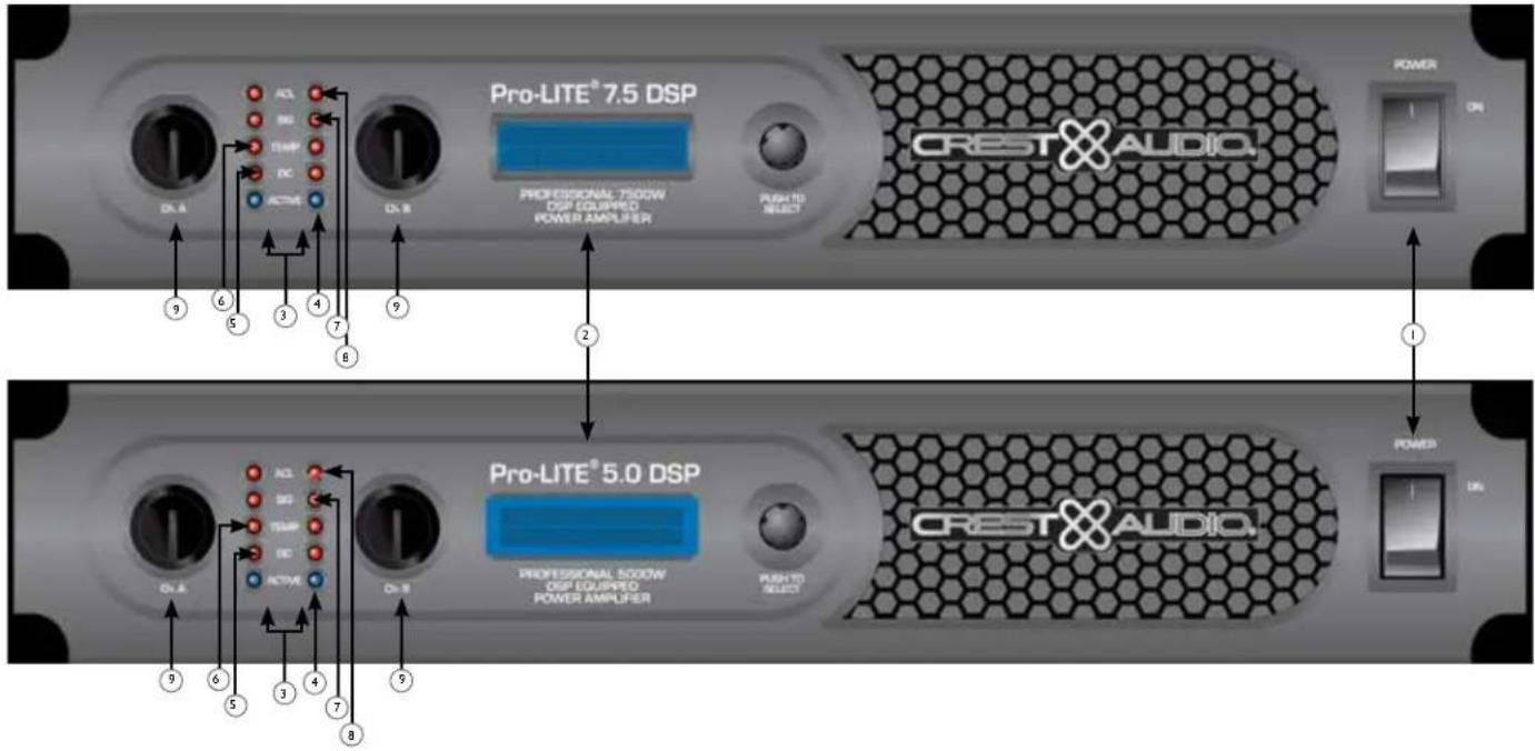
① AC POWER SWITCH
This switch provides power to the amplifier.
2 LCD SCREEN
Blue, backlit LCD screen.
3 INDICATORS
The Pro-LITE® amplifiers feature five front-panel LED indicators per channel: ACTIVE, DC, TEMP, SIGNAL and ACL™. These LED indicators inform the user of each channel's operating status and warn of possible abnormal conditions.
4 ACTIVE LED
The Active LED indicates that the channel is operational. It lights under normal operation and remains on even when the channel is in ACL ™ gain reduction. If the Active LED goes off, there is no signal at the output connectors.
5 DC LED
In the event of abnormal operating conditions, the Pro-LITE ® has built-in amplifier protection. Under conditions that would normally damage the power amplifier, the DC LED will illuminate and the amp will automatically attempt to restart to correct the condition. If the amplifier does not return to normal operating status, contact your local authorized service center.
6 TEMP LED
In the unlikely event of an unstable thermal condition, amplifier protection will be activated and will shut down the offending channel. The Temp LED will remain illuminated until safe operating temperatures have returned.
7 SIGNAL LED
This LED lights when its channel produces an output signal of about 4 volts RMS or more (0.1 volt or more at the input, with 0 dB attenuation and standard x40 voltage gain). This signal indicates whether a signal is reaching and being amplified by the amplifier.
8 ACL™ (Automatic Clip Limiting) LED
A channel's ACL TM LED will light at the onset of clipping. If the LEDs are flashing quickly and intermittently, the channel is just at the clip threshold. A steady, bright glow means the amp is clip limiting or preventing severely clipped waveforms from reaching the loudspeakers. During initial power-up the ACL TM LED will light.
9 INPUT ATTENUATORS
Whenever possible, set the attenuators fully clockwise to maintain optimum system headroom. The input attenuator controls, located at the front panel (one for channel A, one for channel B), adjust gain for their respective amplifier channels in all modes. See the specifications at the end of this manual for standard voltage gain and input sensitivity information.
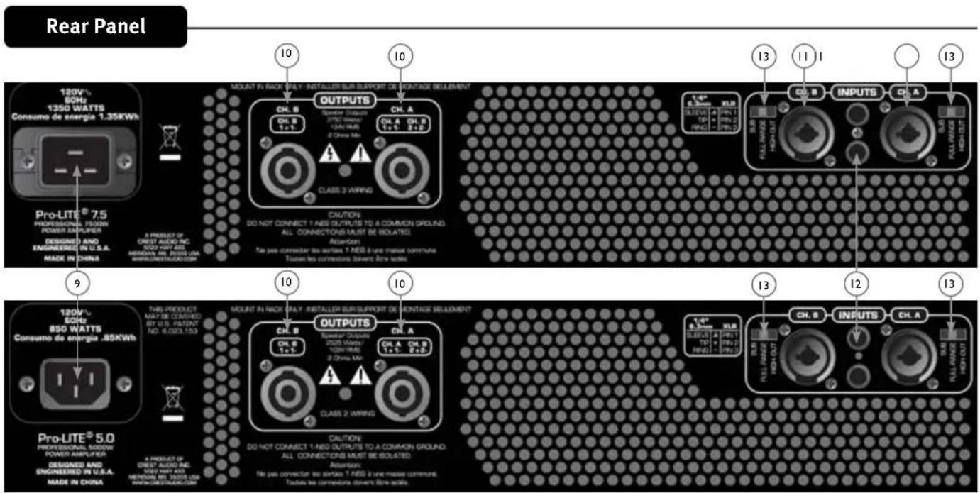
Rear Panel
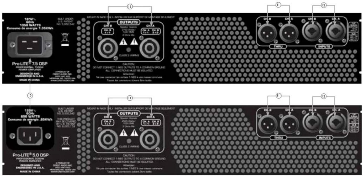
AC POWER INLET:
This is the receptacle for an IEC line cord, which provides AC power to the unit. Connect the line cord to this connector to provide power to the unit. Damage to the equipment may result if improper line voltage is used. (See line voltage marking on unit).
Never break off the ground pin on any equipment. It is provided for your safety. If the outlet used does not have a ground pin, a suitable grounding adapter should be used and the third wire should be grounded properly. To prevent the risk of shock or fire hazard, always make sure that the amplifier and all associated equipment is properly grounded.
NOTE: FOR U.K. ONLY
As the colors of the wires in the mains lead of this apparatus may not correspond with the colored markings identifying the terminals in your plug, proceed as follows: (1) The wire which is colored green and yellow must be connected to the terminal which is marked by the letter E, or by the Earth symbol, or colored green or green and yellow. (2) The wire which is colored blue must be connected to the terminal which is marked with the letter N, or the color black. (3) The wire which is colored brown must be connected to the terminal which is marked with the letter L, or the color red.
THRU/OUT JACKS
This XLR jack supplies parallel output signals from the associated channel for patching to this amplifier and/or additional power amplifier inputs. This XLR jack also provides an unbalanced (tip/sleeve) output to be patched with single-conductor shielded cables.
CONNECTING INPUTS
Input connections are made via the 3-pin XLR (pin 2+) or 6.3 mm plug combination connectors on the rear panel of the amplifier. The inputs are actively balanced. The input overload point is high enough to accept the maximum output level of virtually any signal source.
CONNECTING OUTPUTS
All models have one combination 4 pole twist lock output connector per channel. Channel A output allows for CH A 1+ Pos / 1- Neg and channel B 2+ Pos / 2- Neg to use a single 4 conductor speaker cable.
Navigation Overview
The encoder knob to the right of the display is used to navigate and control the DSP functions. The Channel A and B controls to the left of the display are also encoders but are dedicated to adjusting input gain for each channel. Turning the encoder knob to the right of the display will allow you to scroll through
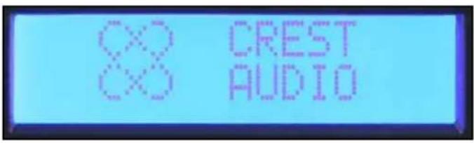
Crest® Pro-LITE™ screen
Once the Crest Audio ® screen appears, you can start adjusting the DSP processor. Pressing the encoder will bring you to the main menu.
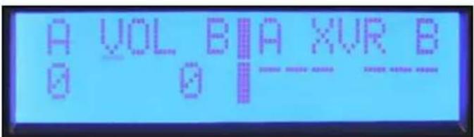
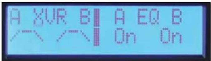
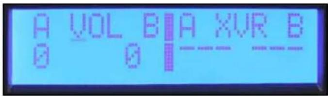
the Main Menu selections. The Main Menu not only allows you to select a process for editing, but also provides a quick view of which processes are activated. From left to right the menu selections are: Input Mode, Volume, Crossover/Band-Pass Filters, Equalization, Delay, Limiting, Memory and Lock.
Input Mode Volume
Crossover / Band-Pass Filters
Equalization
Delay
Limiting
Memory Lock
Navigation Overview continued
To select an item from the Main Menu, rotate the encoder until the cursor marks the selection you want. Press the encoder to navigate to the Sub Menu adjustment screens for that processing function. When you enter a processing function Sub Menu, the cursor will appear in the upper left corner of the screen allowing you to scroll through Sub Menu screens.
To edit a parameter, press the encoder to move the cursor to the desired parameter on the screen. Turning the encoder then adjusts that parameter. To scroll to another screen, press the encoder to return the cursor to the upper left corner of the screen. You can now scroll through Sub Menu screens.
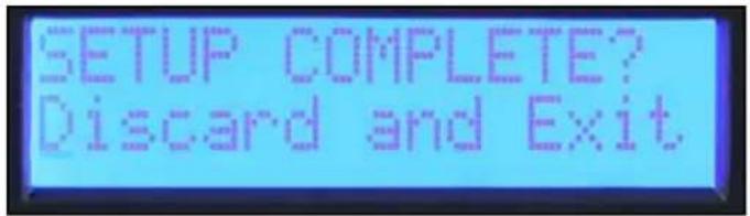
Discard and Exit screen
To reset the DSP and discard edits, select "Discard and Exit" from the Sub Menu to delete the edits made since entering the Sub Menu.
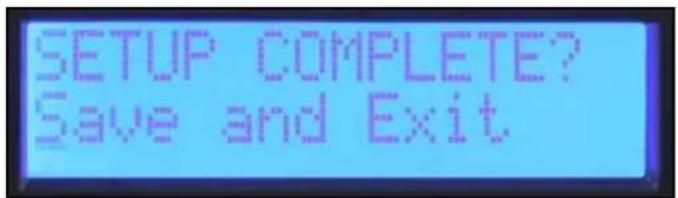
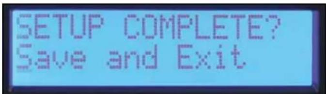
Save and Exit screen
The final screen in most process Sub Menus is "Save and Exit." Press the encoder in this screen to save the edits and return to the main menu.
Note: adjustments made are not stored until Save and Exit is selected and you return to the main menu. Turning off the amplifier while editing in a Sub Menu gives the same result as "Discard and Exit."
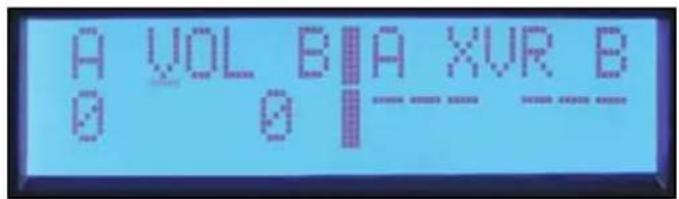
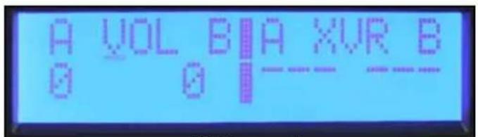
Volume
The current gain settings are always available in the main menu screen. The dedicated encoders on the front panel are used for adjustment of the A and B channels in stereo and mono modes. If the input mode is set to Bridge, the Channel B control is not active and the volume display shows "na."
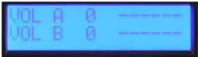
Volume screen
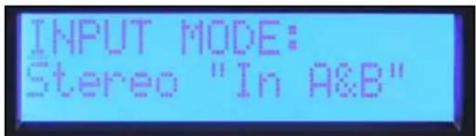
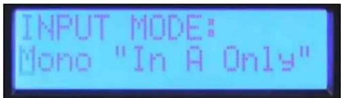
Mode
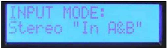
Stereo Mode screen
Stereo: Inputs A and B go to outputs A and B.
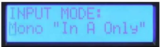
Mono Mode screen
Mono: Input A drives both outputs A and B.
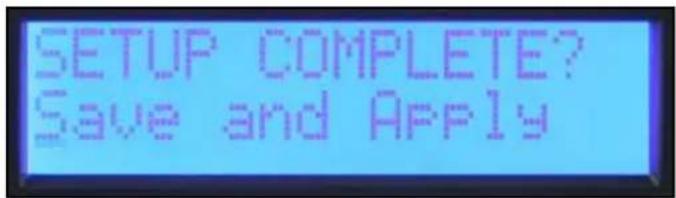
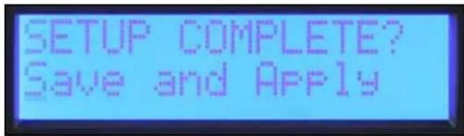
Save and Apply screen
Unlike the other function Sub Menus, the input mode does not change until you select "Save and Apply" and return to the Main Menu.
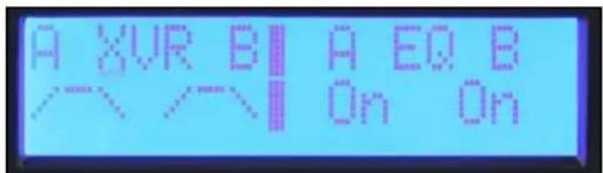
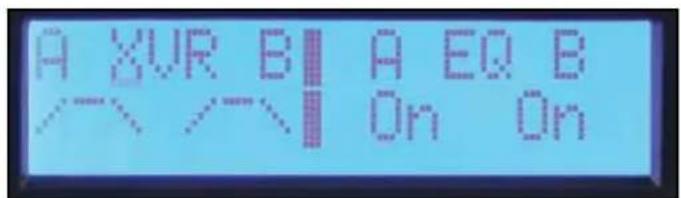
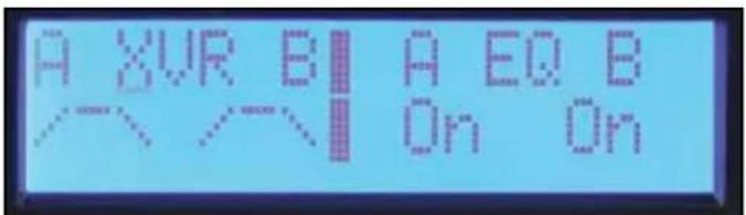
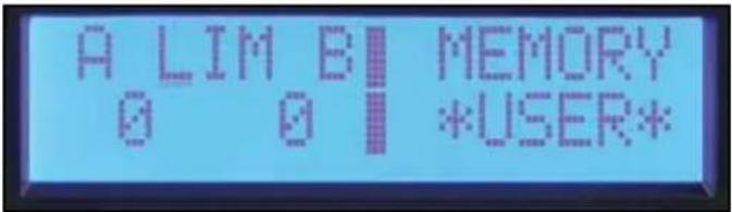
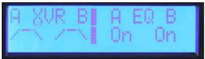
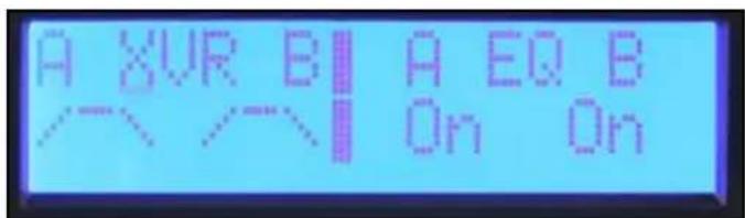
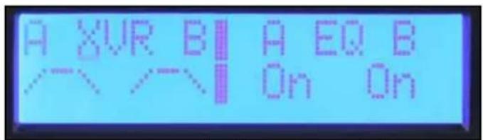
Crossover Filters, Band-Pass Filters and Polarity
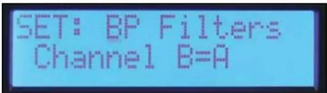
When you enter the "XOVER" Sub Menu, you are given three options for how the band-pass filters can be set. When Set "BP Filters Independently" is selected, the Channel A and B highpass and low-pass filters are individually set.
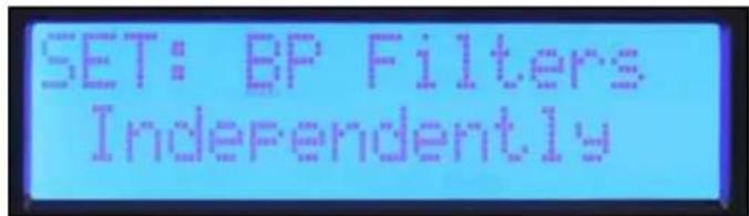
Set: BP Filters Independently screen
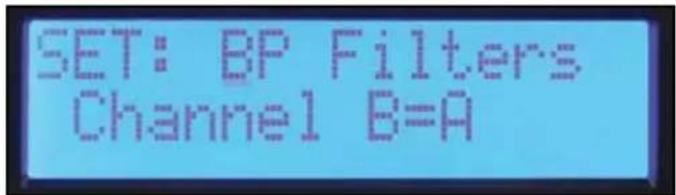
If you are using the amplifier in a stereo system where both channels will be set the same, select "Channel B=A" and both channels will be set at once. Setting the filters for Channel A also sets Channel B.
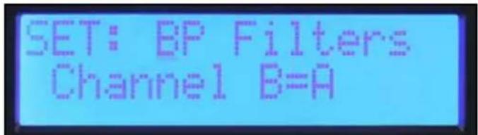
Set: BP Filters Channel B=A screen
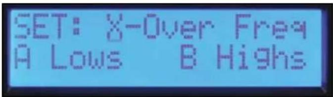
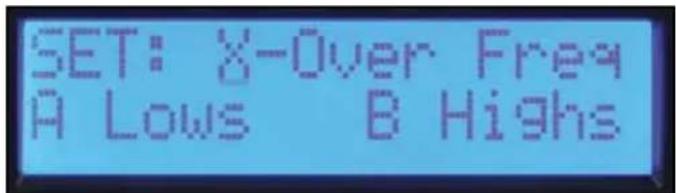
If you create a crossover between channels of the amplifier, select "X-over Freq A Lows B Highs" and crossover frequency and filter type can be set with one set of controls. Set by crossover screen, High-pass and Low-pass screens.
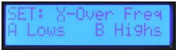
Set: X-Over Freq A Lows B Highs screen
The filter types available for the high-pass and low-pass filters are:
Off No filter
BW-12 dB Butterworth filter with 12 dB per octave slope. -3dB at corner frequency. Butterworth filters have a flat frequency response in the pass-band.
BW-18 dB Butterworth filter with 18 dB per octave slope. -3dB at corner frequency. Butterworth filters have a flat frequency response in the pass-band.
BW-24 dB Butterworth filter with 24 dB per octave slope. -3dB at corner frequency. Butterworth filters have a flat frequency response in the pass-band.
LR-24 dB Linkwitz-Riley Filter with 24 dB per octave slope. -6dB at corner frequency. LR filters combine for a flat response at the corner frequency.
It is generally a good idea to use a high-pass filter for all loudspeakers.
Output Polarity
The output polarity can be inverted on either channel. Select Normal or Invert in the polarity screen. If you create a crossover with 12dB per octave filters, the high frequency output would likely need to be inverted to maintain the proper phase relationship at the crossover frequency. Temporarily inverting the polarity of one channel of a multi-way system can also aid in the setting of the delay for driver alignment. You can adjust the delay for cancellation at the crossover frequency. Remember to switch the polarity back to Normal when complete.
To return to the Main Menu, select Discard and Exit or Save and Exit.
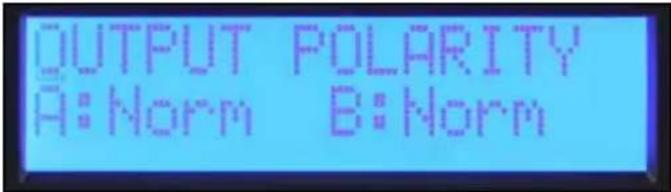
Output Polarity screen
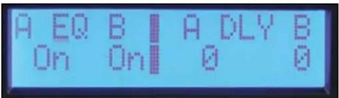
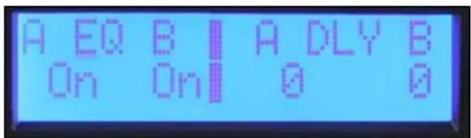
Equalization
The Pro-LITE® DSP provides five bands of parametric EQ, Waves® Maxx Bass® enhancement and horn EQ on each channel.
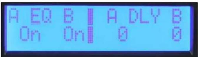
Bypass

EQ bypass screen
The first screen in the EQ Sub Menu is the bypass screen. The channels can be bypassed independently or both A&B can be bypassed together. Press the encoder until the cursor is under the desired parameter to change and rotate the encoder to change the bypass mode. Press the cursor to return it to the upper left corner when done so you can scroll to other screens.
Set Channel EQ
The first screen in the EQ Sub Menu is the bypass screen. The channels can be bypassed independently or both A&B can be bypassed together. Press the encoder until the cursor is under the desired parameter to change and rotate the encoder to change the bypass mode. Press the cursor to return it to the upper left corner when done so you can scroll to other screens.
MaxxBass®
The MaxxBass ® enhancement system interacts with the high-pass filter for each channel to produce bass energy in a frequency range the loudspeaker can handle. The higher the MaxxBass ® number, the more the bass is enhanced.
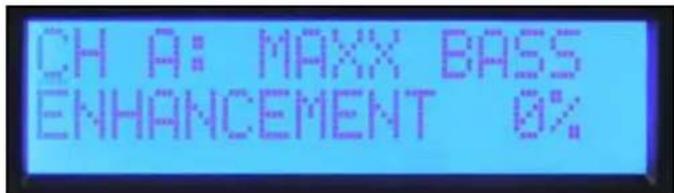
MaxxBass screen
Parametric EQ
There are five bands of parametric EQ for each channel. The frequency can be set in 1/12 octave frequency steps. The filter bandwidth is set and displayed in octaves. The level can be adjusted over a +/- 15 dB range. Press the encoder to select the desired parameter to adjust. Return the cursor to the upper left corner when done to scroll to other screens.
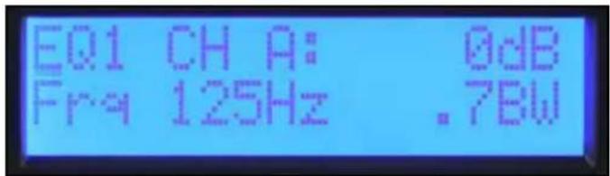
Parametric EQ screen
Horn EQ
The Horn EQ provides a 6dB per octave high frequency boost that is sometimes required for high frequency horns. The frequency control sets the low frequency corner of the filter.
To return to the Main Menu, select Discard and Exit or Save and Exit.
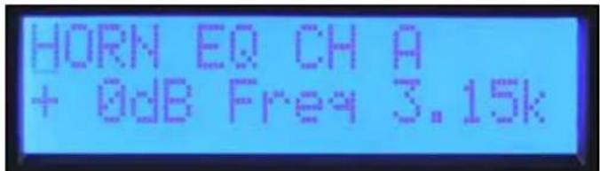
Horn EQ screen
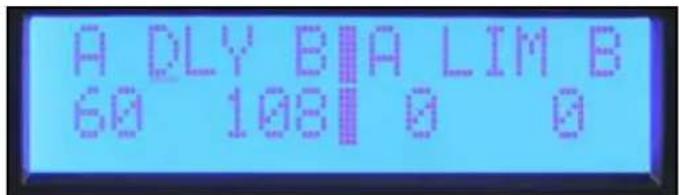
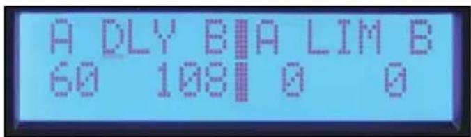
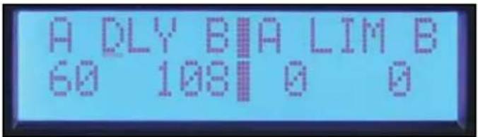
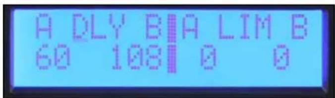
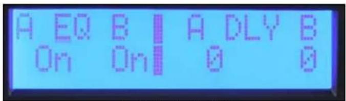
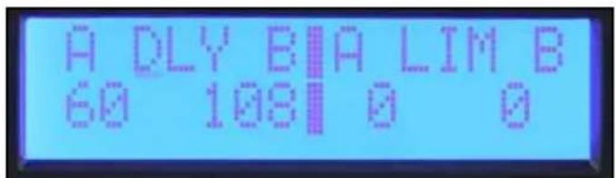
Delay
Delay can be used to align drivers within a loudspeaker or to delay auxiliary speakers like those installed under a balcony. A short delay can also be used to delay the main speakers to align them with the drums or bass guitar. A total of 125 mS of delay is available on each channel. 5 mS of delay is available in 41.67 uS steps for driver alignment. 120 mS is available in 1 mS steps for system alignment. These delays can be set independently so that the driver alignment offset can be maintained when the system alignment delay is adjusted.
The first screen in the delay Sub Menu allows the user to decide whether the delays will be set independently or B=A. This selection only applies to the 1 mS step system delay, leaving the driver alignment delays to be set independently. The Pro-LITE™ DSP amplifiers display the equivalent delay distance in meters and feet in the system delay and centimeters or inches in the driver delay.
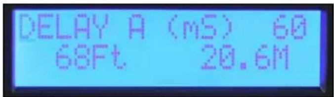
System (mS) Delay screen
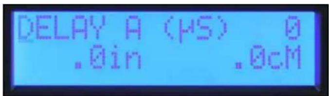
Driver alignment (uS) screen
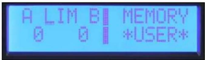
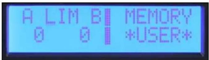
Limiter
The Pro-LITE® DSP has limiters available on each channel. These limit the signal level to the input of the power amplifier stage. The limit threshold starts at zero and is adjusted in -1 dB steps, reducing the maximum output. You must be aware that the Pro-LITE® DSP works the same as most other amplifiers in that their maximum output depends on the line voltage and load impedance. Depending on load, you may need to reduce the limiter up to 3 dB before the output is reduced.
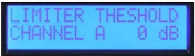
Limiter screen
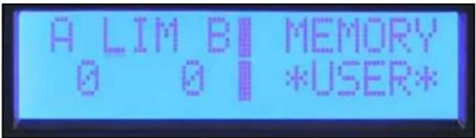
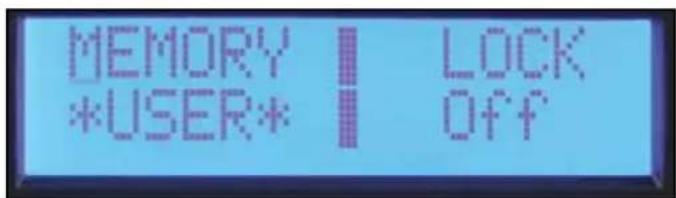
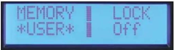
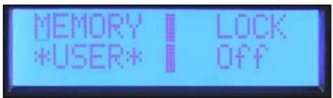
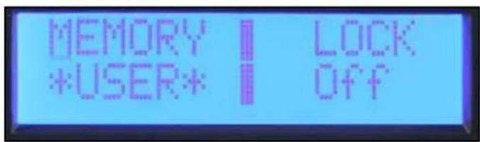
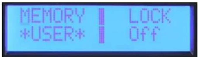
Memory
The Pro-LITE ® has four memory locations where its settings can be stored and then recalled. Each location has a six-character name to identify the file. The name of the active preset is also displayed in the Main Menu “Memory” screen.
Saving Settings
In the Memory Operation Sub Menu, select "Save Settings."
Select one of the four preset locations. Edit the name by rotating the cursor to select the character and pressing the encoder to step to the next position. Continue until complete. To keep the same name, press the encoder six times to step through the name edit screen.
Once the save location has been selected and you have named the preset, you will be given a yes/no option to complete the save.
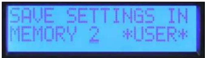
Save Settings screen
Recalling a Preset
In the Memory Operation Sub Menu, select "Recall Settings."
Select the Preset number to recall or select recall factory settings to recall a neutral state. Just like the save function, the option is given to exit without completing the recall option.
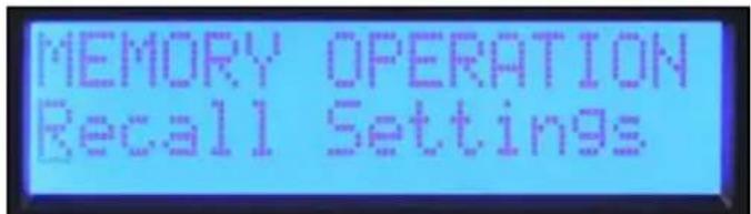
Recall Preset screen
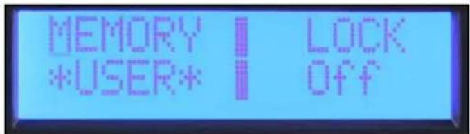
Lock
The security lock feature of the Pro-LITE ® DSP allows selected controls to be locked to prevent unauthorized adjustment. A four digit password must be set when the lock is engaged. This password must be entered whenever a Sub Menu is entered to allow temporary access to the edit functions. The lock is re-engaged whenever you return the Main Menu or turn the unit off. All editing is locked when the power is off.
Note: Be sure to make note of the password. Contact customer service if the password is lost or misplaced.
The Pro-LITE™ amplifiers have three different lock modes:
Off All settings can be adjusted without entering a password.
All Except Volume A password must be entered for all edit Sub Menus except volume.
All with Volume A password must be entered for all edit Sub Menus including volume.
Pro-LITE® 7.5 Specification Sheet
Rated Watts 2ch x 2 ohms 4800 watts 20ms repetitive burst / 3790 watts 1% THD both channels driven @ 1kHz.
Rated Watts 2ch x 4 ohms driven @ 1kHz. 2810 watts 20ms repetitive burst / 2450 watts 1% THD / 2030 watts 0.15% THD, both channels
Rated Watts 2ch x 8 ohms 1550 watts 20ms repetitive burst / 1425 watts 1% THD / 1200 watts 0.15% THD, both channels driven @ 1kHz.
Minimum Impedance 2 ohms
Maximum RMS Voltage Swing 124 volts
Frequency Response 20Hz - 25kHz; +0dB, -3dB
20Hz - 20kHz 2ch x 2 ohms <0.5% @ 3390 watts 20Hz to 4kHz, decreasing to 3100 watts @ 20kHz, both channels driven.
20Hz - 20kHz 2ch x 4 ohms <0.15% @ 1850 watts 20Hz to 20kHz, both channels driven.
20Hz - 20kHz 2ch x 8 ohms <0.15% @ 1170 watts 20Hz to 20kHz, both channels driven.
Input CMRR > - 75dB @ 1 kHz.
Voltage Gain × 40 (+32dB)
Crossover 100Hz switchable 2nd order high pass and 3rd low pass per channel.
Crosstalk > -60dB @ 1kHz @ 1000 watts power @ 8 ohms.
Hum and Noise > -100dB, "A" weighted referenced to rated power @ 4 ohms.
Slew Rate > 12V/μs
Damping Factor (8 ohms) > 200:1 @ 20Hz - 1kHz @ 8 ohms
Phase Response +15 to -85 degrees from 20Hz to 20kHz
Input Sensitivity 2.25 volts +/- 3% for 1kHz 4 ohm rated power, 2.2 volts +/- 3% for 1kHz 2 ohm rated power
Input Impedance 20 kilohms, balanced and 10 kilohms unbalanced.
Current Draw @ 1/8 in VA (watts) 2210 (1440) @ 2 ohms, 1550 (950) @ 4 ohms, 985 (560) @ 8 ohms
Current Draw @ 1/3 in VA (watts) 4260 (3|50) @ 2 ohm, 3|20 (2|60) @ 4 ohms, 1890 (1200) @ 8 ohms
Idle Consumption 250VA, 120 watts.
Cooling 3 temperature dependent variable speed fans.
Controls 2 front panel attenuators, crossover select switch for HPF, Normal and LPF
Indicator LEDs Five LED indicators per channel: Active, Signal, ACL, Temperature and DC
Protection Thermal, DC, subsonic, incorrect loads, under and over voltage
Connectors Inputs: Dual combination 1/4" XLR, Outputs: Dual 1/4" thru, one 2-pin & one 4 pin twist-lock connector
Construction 0.062" thick aluminum
Dimensions 3.5"x19"x17" behind front panel + 0.6" for handle
Net Weight 6.61kg (14.6lbs.*)
Gross Weight 8.34kg (18.4lbs.)
Rated power readings made with BW: 20 Hz to 22 kHz. All power measurements made @ 120 VAC or 240VAC.
2 ohm steady state sine wave power is time limited by circuit breaker.
Bridge operation is not possible.
*Net Weight does not include power cord.
Pro-LITE® 5.0 Specification Sheet
Rated Watts 2ch x 2 ohms 3300 watts 20ms repetitive burst / 2600 watts 1% THD both channels driven @ 1kHz.
Rated Watts 2ch x 4 ohms driven @ 1kHz. 2025 watts 20ms repetitive burst / 1725 watts 1% THD / 1500 watts 0.2% THD, both channels
Rated Watts 2ch x 8 ohms 1175 watts 20ms repetitive burst / 1000 watts 1% THD / 825 watts 0.2% THD, both channels driven @ 1kHz.
Minimum Impedance 2 ohms
Maximum RMS Voltage Swing 105 volts
Frequency Response 20Hz - 22kHz; +/-0.5dB @ I watt.
20Hz - 20kHz 2ch x 2 ohms <0.5% @ 2250 watts 20Hz to 4kHz, decreasing to 1650 watts @ 20kHz, both channels driven.
20Hz - 20kHz 2ch x 4 ohms <0.15% @ 1400 watts 20Hz to 10kHz, decreasing to 1350 watts @20kHz, both channels driven.
20Hz - 20kHz 2ch x 8 ohms <0.15% @ 860 watts 20Hz to 4kHz, increasing to 1000 watts @ 20kHz, both channels driven.
Input CMRR > - 75dB @ 1 kHz.
Voltage Gain × 40 (+32dB)
Crossover 100Hz switchable 2nd order high pass and 3rd low pass per channel.
Crosstalk > -60dB @ 1kHz @ 700 watts power @ 8 ohms.
Hum and Noise > -105dB, "A" weighted referenced to rated power @ 4 ohms.
Slew Rate > 12V/μs
Damping Factor (8 ohms) > 210:1 @ 20Hz - 1kHz @ 8 ohms
Phase Response +5 to -91 degrees from 20Hz to 20kHz
Input Sensitivity 1.95 volts +/- 3% for 1kHz 4 ohm rated power, 1.83 volts +/- 3% for 1kHz 2 ohm rated power
Input Impedance 20 kilohms, balanced and 10 kilohms unbalanced.
Current Draw @ 1/8 in VA (watts) 1435 (890) @ 2 ohms, 920 (525) @ 4 ohms, 625 (335) @ 8 ohms
Current Draw @ 1/3 in VA (watts) 3050 (2155) @ 2 ohm, 1880 (1200) @ 4 ohms, 1200 (715) @ 8 ohms
Idle Consumption 195VA, 90 watts.
Cooling 3 temperature dependent variable speed fans.
Controls 2 front panel attenuators, crossover select switch for HPF, Normal and LPF
Indicator LEDs Five LED indicators per channel: Active, Signal, ACL, Temperature and DC
Protection Thermal, DC, subsonic, incorrect loads, under and over voltage
Connectors Inputs: Dual combination 1/4" XLR, Outputs: Dual 1/4" thru, one 2-pin & one 4 pin twist-lock connector
Construction 0.062" thick aluminum
Dimensions 3.5"x19"x17" behind front panel + 0.6" for handle
Net Weight 6.2kg (13.6lbs.*)
Gross Weight 7.9kg (17.4lbs.)
Rated power readings made with BW: 20 Hz to 22 kHz. All power measurements made @ 120 VAC or 240VAC.
2 ohm steady state sine wave power is time limited by circuit breaker.
Bridge operation is not possible.
*Net Weight does not include power cord.
Pro-LITE® 7.5 DSP Specification Sheet
Rated Watts 2ch x 2 ohms 4780 watts 20ms repetitive burst / 3740 watts 1% THD both channels driven @ 1kHz.
Rated Watts 2ch x 4 ohms driven @ 1kHz. 2810 watts 20ms repetitive burst / 2475 watts 1% THD / 2160 watts 0.2% THD, both channels
Rated Watts 2ch x 8 ohms driven @ 1kHz. 1550 watts 20ms repetitive burst / 1475 watts 1% THD / 1270 watts 0.2% THD, both channels
Minimum Impedance 2 ohms
Maximum RMS Voltage Swing 124 volts
Frequency Response 20Hz - 25kHz; +0dB, -3dB
20Hz - 20kHz 2ch x 2 ohms <0.5% @ 3390 watts 20Hz to 4kHz, decreasing to 2000 watts @ 20kHz, both channels driven.
20Hz - 20kHz 2ch x 4 ohms <0.15% @ 2000 watts 20Hz to 20kHz, both channels driven.
20Hz - 20kHz 2ch x 8 ohms <0.15% @ 1150 watts 20Hz to 20kHz, both channels driven.
Input CMRR > - 75dB @ 1 kHz.
Voltage Gain × 70 (+37dB)
Crossover Adjustable High Pass and Low Pass filter per channel. Filter Types: 12dB/oct 2nd order, 18dB/oct 3rd order, 24dB/oct 4th order Butterworth and 24dB/oct 4th order Linkwitz-Riley
Crosstalk > -60dB @ 1kHz @ 1000 watts power @ 8 ohms.
Hum and Noise > -96dB, "A" weighted referenced to rated power @ 4 ohms.
Slew Rate > 12V/μs
Damping Factor (8 ohms) > 200:1 @ 20Hz - 1kHz @ 8 ohms
Input Sensitivity 1.340 volts +/- 3% for 1kHz 4 ohm rated power; 1.250 volts +/- 3% for 1kHz 2 ohm rated power
Input Impedance 12 kilohms, balanced and 10 kilohms unbalanced.
Current Draw @ 1/8 in VA (watts) 2210 (1440) @ 2 ohms, 1550 (950) @ 4 ohms, 985 (560) @ 8 ohms
Current Draw @ 1/3 in VA (watts) 4260 (3150) @ 2 ohm, 3120 (2160) @ 4 ohms, 1890 (1200) @ 8 ohms
Idle Consumption 250VA, 120 watts
Cooling 3 temperature dependent variable speed fans.
Controls 2 front panel attenuators, push-button navigation encoder to navigate through the menus on the LCD screen for input mode, parametric EQ, crossover select switch for HPF, Normal and LPF
Indicator LEDs Five LED indicators per channel: Active, Signal, ACL, Temperature and DC
Protection Thermal, DC, subsonic, incorrect loads, under and over voltage
Connectors twist-lock connector Inputs: Dual combination 1/4" XLR, Outputs: Dual male XLR input thru, one 2-pin & one 4 pin
Construction 0.062" thick aluminum
Dimensions 3.5"x19"x 17.25" behind front panel + 0.75" for handle
Net Weight 6.9kg (15.2lbs.*)
Gross Weight 8.6kg (19.0lbs.)
Rated power readings made with BW: 20 Hz to 22 kHz. All power measurements made @ 120 VAC or 240VAC.
2 ohm steady state sine wave power is time limited by circuit breaker.
Bridge operation is not possible.
*Net Weight does not include power cord.
Pro-LITE® 5.0 DSP Specification Sheet
Rated Watts 2ch x 2 ohms
3300 watts 20ms repetitive burst / 2600 watts 1% THD both channels driven @ 1kHz.
Rated Watts 2ch x 4 ohms driven @ 1kHz.
2000 watts 20ms repetitive burst / 1700 watts 1% THD / 1500 watts 0.2% THD, both channels
Rated Watts 2ch x 8 ohms @ 1kHz.
1175 watts 20ms repetitive burst / 1000 watts 1% THD / 825 watts 0.2% THD, both channels driven
Minimum Impedance 2 ohms
Maximum RMS Voltage Swing 100 volts
Frequency Response 20Hz - 22kHz; +/-0.5dB @ I watt.
20Hz - 20kHz 2ch x 2 ohms
<0.5% @ 2250 watts 20Hz to 4kHz, decreasing to 1650 watts @ 20kHz, both channels driven.
20Hz - 20kHz 2ch x 4 ohms
<0.15% @ 1400 watts 20Hz to 10kHz, decreasing to 1350 watts @20kHz, both channels driven.
20Hz - 20kHz 2ch x 8 ohms
<0.15% @ 830 watts 20Hz to 4kHz, increasing to 1000 watts @ 20kHz, both channels driven.
Input CMRR > - 75dB @ 1 kHz.
Voltage Gain × 70 (+37dB)
Crossover Adjustable High Pass and Low Pass filter per channel.
Filter Types: 12dB/oct 2nd order, 18dB/oct 3rd order, 24dB/oct 4th order Butterworth and 24dB/oct 4th order Linkwitz-Riley.
Crosstalk > -60dB @ 1kHz @ 700 watts power @ 8 ohms.
Hum and Noise
-96dB, "A" weighted referenced to rated power @ 4 ohms.
Slew Rate > 12V/μs
Damping Factor (8 ohms)
210:1 @ 20Hz - 1kHz @ 8 ohms
Input Sensitivity
1.11 volts +/- 3% for 1kHz 4 ohm rated power, 1.04 volts +/- 3% for 1kHz 2 ohm rated power
Input Impedance
12 kilohms, balanced and 6 kilohms unbalanced.
Current Draw @ I/8 in VA (watts)
1435 (890) @ 2 ohms, 920 (525) @ 4 ohms, 625 (335) @ 8 ohms
Current Draw @ 1/3 in VA (watts)
3050 (2155) @ 2 ohm, 1880 (1200) @ 4 ohms, 1200 (715) @ 8 ohms
Idle Consumption
195VA, 90 watts.
Cooling
3 temperature dependent variable speed fans.
Controls
2 front panel attenuators, push-button navigation encoder to navigate through the menus on the LCD screen for input mode, parametric EQ, crossover select switch for HPF, Normal and LPF
Indicator LEDs
Five LED indicators per channel: Active, Signal, ACL, Temperature and DC
Protection
Thermal, DC, subsonic, incorrect loads, under and over voltage
Connectors
Inputs: Dual combination 1/4" XLR, Outputs: Dual 1/4" thru, one 2-pin & one 4 pin twist-lock connector
Construction
0.062" thick aluminum
Dimensions
3.5"x19"x 17.25" behind front panel + 0.75" for handle
Net Weight
6.4kg (14.2lbs.*)
Gross Weight
8.2kg (18.0lbs.)
Rated power readings made with BW: 20 Hz to 22 kHz. All power measurements made @ 120 VAC or 240VAC.
2 ohm steady state sine wave power is time limited by circuit breaker.
Bridge operation is not possible.
*Net Weight does not include power cord.
ESPAÑOL
Pro-LITE™ 5.0 / 7.5
7 LED ACL™ (Automatic Clip Limiting)
As the colors of the wires in the mains lead of this apparatus may not correspond with the colored markings identifying the terminals in your plug, proceed as follows: (1) The wire which is colored green and yellow must be connected to the terminal which is marked by the letter E, or by the Earth symbol, or colored green or green and yellow. (2) The wire which is colored blue must be connected to the terminal which is marked with the letter N, or the color black. (3) The wire which is colored brown must be connected to the terminal which is marked with the letter L, or the color red.

CONNECTING OUTPUTS
Pro-LITE™ DSP 5.0 / 7.5
⑧ LED ACL™ (Automatic Clip Limiting)
As the colors of the wires in the mains lead of this apparatus may not correspond with the colored markings identifying the terminals in your plug, proceed as follows: (1) The wire which is colored green and yellow must be connected to the terminal which is marked by the letter E, or by the Earth symbol, or colored green or green and yellow. (2) The wire which is colored blue must be connected to the terminal which is marked with the letter N, or the color black. (3) The wire which is colored brown must be connected to the terminal which is marked with the letter L, or the color red.
CONECTORES THRU/OUT
Pantalla Guardar y Aplicar
Set: Pantalla BP Filters Channel B=A

Set: Pantalla X-Over Freq A Lows B Highs
Pantalla Output Polarity
Ecualización
Pantalla EQ BYPASS
Pantalla MaxxBass
EQ paramétrico
Pantalla Limiter
Memoria
Pantalla Guardar ajustes
Tipos de filtros: 12 dB/ oct 2nd order, 18 dB/ oct 3rd order, 24 dB/ oct 4th order Butterworth y Linkwitz –Riley 24 dB/ oct 4th orden
Crosstalk > -60dB a 1kHz a 1000 watts de potencia a 8 ohms.
Tipos de filtros: 12 dB/ oct 2nd order, 18 dB/ oct 3rd order, 24 dB/ oct 4th order Butterworth y Linkwitz –Riley 24 dB/ oct 4th order
Crosstalk > -60dB a 1kHz a 700 watts de potencia a 8 ohms.
As the colors of the wires in the mains lead of this apparatus may not correspond with the colored markings identifying the terminals in your plug, proceed as follows: (1) The wire which is colored green and yellow must be connected to the terminal which is marked by the letter E, or by the Earth symbol, or colored green or green and yellow. (2) The wire which is colored blue must be connected to the terminal which is marked with the letter N, or the color black. (3) The wire which is colored brown must be connected to the terminal which is marked with the letter L, or the color red.
CONNEXION DES SORTIES
Pro-LITE™ DSP 5.0 / 7.5
As the colors of the wires in the mains lead of this apparatus may not correspond with the colored markings identifying the terminals in your plug, proceed as follows: (1) The wire which is colored green and yellow must be connected to the terminal which is marked by the letter E, or by the Earth symbol, or colored green or green and yellow. (2) The wire which is colored blue must be connected to the terminal which is marked with the letter N, or the color black. (3) The wire which is colored brown must be connected to the terminal which is marked with the letter L, or the color red.
PRISE THRU/OUT
Mode entrée Volume
Écran de mode mono
Écran MaxxBass
Écran de limiteur
Mémoire
Types de filtres : 12dB/oct 2nd order, 18 dB/oct 3rd order, 24 dB/oct 4th order Butterworth et
24 dB/oct 4th order Linkwitz-Riley
⑦ ACL™ (Automatic Clip Limiting)-LED
As the colors of the wires in the mains lead of this apparatus may not correspond with the colored markings identifying the terminals in your plug, proceed as follows: (1) The wire which is colored green and yellow must be connected to the terminal which is marked by the letter E, or by the Earth symbol, or colored green or green and yellow. (2) The wire which is colored blue must be connected to the terminal which is marked with the letter N, or the color black. (3) The wire which is colored brown must be connected to the terminal which is marked with the letter L, or the color red.
Pro-LITE™ DSP 5.0 / 7.5
Verstärker
ACL™ (Automatic Clip Limiting)-LED
As the colors of the wires in the mains lead of this apparatus may not correspond with the colored markings identifying the terminals in your plug, proceed as follows: (1) The wire which is colored green and yellow must be connected to the terminal which is marked by the letter E, or by the Earth symbol, or colored green or green and yellow. (2) The wire which is colored blue must be connected to the terminal which is marked with the letter N, or the color black. (3) The wire which is colored brown must be connected to the terminal which is marked with the letter L, or the color red.
THRU/OUT-BUCHSEN
Drosselung
Verzögerung
Speichersperre
Bildschirm MaxxBass
Parametrischer EQ
24dB/oct 4th order Linkwitz-Riley
As the colors of the wires in the mains lead of this apparatus may not correspond with the colored markings identifying the terminals in your plug, proceed as follows: (1) The wire which is colored green and yellow must be connected to the terminal which is marked by the letter E, or by the Earth symbol, or colored green or green and yellow. (2) The wire which is colored blue must be connected to the terminal which is marked with the letter N, or the color black. (3) The wire which is colored brown must be connected to the terminal which is marked with the letter L, or the color red.

Pro-LITE™ DSP 5.0 / 7.5
As the colors of the wires in the mains lead of this apparatus may not correspond with the colored markings identifying the terminals in your plug, proceed as follows: (1) The wire which is colored green and yellow must be connected to the terminal which is marked by the letter E, or by the Earth symbol, or colored green or green and yellow. (2) The wire which is colored blue must be connected to the terminal which is marked with the letter N, or the color black. (3) The wire which is colored brown must be connected to the terminal which is marked with the letter L, or the color red.
JACK THRU/OUT
Filtri Crossover / Band-Pass
Equalizzazione
Ritardo
Limitazione
Blocco memoria
Schermata Discard and Exit
Schermata Save and Exit
Schermata Save and Apply
Schermata Set: BP Filters Independently
Schermata Set: BP Filters Channel B=A
Schermata Set: X-Over Freq A Lows B Highs
Schermata EQ bypass
Schermata MaxxBass
EQ parametrico
Schermata Limiter
Memoria
Schermata save settings
Ingresso CMRR > - 75dB @ 1 kHz.
Crosstalk > -60dB @ 1kHz @ 700 watt potenza @ 8 ohm.
Assorbimento @ 1/3 in VA (watt) 3050 (2155) @ 2 ohm, 1880 (1200) @ 4 ohm, 1200 (715) @ 8 ohm
Consumo inutile 195VA, 90 watt.
Ingresso CMRR > - 75dB @ 1 kHz.
Tipi di filtro: 12dB/oct 2nd order, 18dB/oct 3rd order, 24dB/oct 4th order Butterworth e 24dB/oct 4th order Linkwitz-Riley
Crosstalk > -60dB @ 1kHz @ 1000 watt potenza @ 8 ohm.
Ronzio e rumore
2210 (1440) @ 2 ohm, 1550 (950) @ 4 ohm, 985 (560) @ 8 ohm
4260 (3150) @ 2 ohm, 3120 (2160) @ 4 ohm, 1890 (1200) @ 8 ohm
Consumo inutile
250VA, 120 watt
Raffreddamento
crossover HPF, Normal e LPF.
LED indicatore
Ingresso CMRR > - 75dB @ 1 kHz.
Tipo di filtro: 12dB/oct 2nd order, 18dB/oct 3rd order, 24dB/oct 4th order Butterworth e
24dB/oct 4th order Linkwitz-Riley.
Crosstalk > -60dB @ 1kHz @ 700 watt potenza @ 8 ohm.
Ronzio e rumore
1435 (890) @ 2 ohm, 920 (525) @ 4 ohm, 625 (335) @ 8 ohm
As the colors of the wires in the mains lead of this apparatus may not correspond with the colored markings identifying the terminals in your plug, proceed as follows: (1) The wire which is colored green and yellow must be connected to the terminal which is marked by the letter E, or by the Earth symbol, or colored green or green and yellow. (2) The wire which is colored blue must be connected to the terminal which is marked with the letter N, or the color black. (3) The wire which is colored brown must be connected to the terminal which is marked with the letter L, or the color red.
CONEXÃO DAS SAÍDAS
Pro-LITE™ DSP 5.0 / 7.5
As the colors of the wires in the mains lead of this apparatus may not correspond with the colored markings identifying the terminals in your plug, proceed as follows: (1) The wire which is colored green and yellow must be connected to the terminal which is marked by the letter E, or by the Earth symbol, or colored green or green and yellow. (2) The wire which is colored blue must be connected to the terminal which is marked with the letter N, or the color black. (3) The wire which is colored brown must be connected to the terminal which is marked with the letter L, or the color red.
CONECTOR THRU/OUT
Tela Crest® Pro-LITE™
Tela Discard and Exit
Tela Save and Exit
Tela Modo Estéreo
Tela Modo Mono
Tela Save and Apply
Tela BP Filters Independently
Tela BP Filters Channel B=A
Tela X-Over Freq A Lows B Highs
Tela Output Polarity
Equalização
Tela EQ Bypass
Tela MaxxBass
Tela Limitador
Memória
Tela save settings
Pro-LITE™ DSP 5.0 / 7.5
パワーアンプ
As the colors of the wires in the mains lead of this apparatus may not correspond with the colored markings identifying the terminals in your plug, proceed as follows: (1) The wire which is colored green and yellow must be connected to the terminal which is marked by the letter E, or by the Earth symbol, or colored green or green and yellow. (2) The wire which is colored blue must be connected to the terminal which is marked with the letter N, or the color black. (3) The wire which is colored brown must be connected to the terminal which is marked with the letter L, or the color red.
THRU/OUTジャック
Crest® Pro-LITE™ 画面
入力モード
ボリューム
制限
メモリロック
ナビゲーションの概要(続き)
削除と終了画面
保存と終了画面
ステレオモード動作
モノモード画面
保存と適用画面
出力極性画面
イコライゼーション
EQ バイパス画面
MaxxBass 画面
リミッター画面
メモリ
設定保存画面
プリセットの呼び出し
24dB/oct 4th order Butterworth, 24dB/oct 4th order Linkwitz –Riley
As the colors of the wires in the mains lead of this apparatus may not correspond with the colored markings identifying the terminals in your plug, proceed as follows: (1) The wire which is colored green and yellow must be connected to the terminal which is marked by the letter E, or by the Earth symbol, or colored green or green and yellow. (2) The wire which is colored blue must be connected to the terminal which is marked with the letter N, or the color black. (3) The wire which is colored brown must be connected to the terminal which is marked with the letter L, or the color red.
10 连接输出
Pro-LITE™ DSP 5.0 / 7.5
功率放大器
As the colors of the wires in the mains lead of this apparatus may not correspond with the colored markings identifying the terminals in your plug, proceed as follows: (1) The wire which is colored green and yellow must be connected to the terminal which is marked by the letter E, or by the Earth symbol, or colored green or green and yellow. (2) The wire which is colored blue must be connected to the terminal which is marked with the letter N, or the color black. (3) The wire which is colored brown must be connected to the terminal which is marked with the letter L, or the color red.
直通/输出插孔
Crest® Pro-LITE™ 显示屏
Input Mode(输入模式)
Volume (音量)
Crossover / Band-Pass Filters (分频/带通滤波器)
Equalization(均衡)
Delay(延迟)
Limiting (限幅)
Memory Lock(内存锁止)
导航概述(继续)
Discard and Exit屏幕
Save and Exit 屏幕
Stereo Mode(立体声模式)屏幕
立体声:输入A和B进输出A和B。
Mono Mode(单声道模式)屏幕
单声道:输入A同时驱动输出A和B。
Save and Apply 屏幕
设置: BP Filters Independently 屏幕
设置: BP Filters Channel B=A 屏幕
设置: X-Over Freq A Lows B Highs 屏幕
可用于高通和低通滤波器的滤波器类型有:
关闭 无滤波器
Output Polarity(输出极性)屏幕
Equalization(均衡)
EQ 旁通屏幕
MaxxBass 屏幕
参数EQ
限幅器屏幕
内存
Save Settings 屏幕
调出预设置
As the colors of the wires in the mains lead of this apparatus may not correspond with the colored markings identifying the terminals in your plug, proceed as follows: (1) The wire which is colored green and yellow must be connected to the terminal which is marked by the letter E, or by the Earth symbol, or colored green or green and yellow. (2) The wire which is colored blue must be connected to the terminal which is marked with the letter N, or the color black. (3) The wire which is colored brown must be connected to the terminal which is marked with the letter L, or the color red.
출력 연결
Pro-LITE™ DSP 5.0 / 7.5
파워 엠프
As the colors of the wires in the mains lead of this apparatus may not correspond with the colored markings identifying the terminals in your plug, proceed as follows: (1) The wire which is colored green and yellow must be connected to the terminal which is marked by the letter E, or by the Earth symbol, or colored green or green and yellow. (2) The wire which is colored blue must be connected to the terminal which is marked with the letter N, or the color black. (3) The wire which is colored brown must be connected to the terminal which is marked with the letter L, or the color red.
THRU/OUT 잡
입력 모드 볼륨

크로스오버/밴드-페스 필터
이 Joel라이제이션
덜레이
제한
메모리 및 잠금
탐색 개요 계속
버리고 나가기 화면
저장하고 나가기 화면
스테레오 모드 화면
모노 모드 화면
저장 및 적용 화면
설정:BP 필터 개별 설정 화면
설정:BP 필터 채널 B=A 화면
출력 극성 화면
이킬라이제이션
EQ 우회 화면
MaxxBass 화면
파라미터 EQ
리미터 화면
설정 저장 화면
프리셋 불러오기
입력 CMRR > - 75dB @ 1 kHz.
전압 게인 × 40 (+32dB)
Crossover
200:1 @ 20Hz - 1kHz @ 8 ohms
위상 응답
+15 \~ -85Hz, 20Hz \~ 20kHz
입력 감도


- Pro-LITE® 5.0 / 7.5 DSP
- Owner's Manual
- CREST AUDIO®
- IMPORTANT SAFETY INSTRUCTIONS
- SAVE THESE INSTRUCTIONS!
- FCC Compliancy Statement
- ENGLISH
- Pro-LITE® 5.0 / 7.5
- Power Amplifiers
- Pro-LITE® Features:
- Front Panel
- ① AC POWER SWITCH
- INDICATORS
- ACTIVE LED
- DC LED
- TEMP LED
- SIGNAL LED
- ⑦ ACL™ (Automatic Clip Limiting) LED
- ⑧ INPUT ATTENUATORS
- AC POWER INLET:
- NOTE: FOR U.K. ONLY
- CONNECTING OUTPUTS
- CONNECTING INPUTS
- THRU/OUT JACKS
- CHANNEL MODE SWITCH
- HIGH PASS
- FULL RANGE
- SUBWOOFER
- Pro-LITE® DSP 5.0 / 7.5
- Pro-LITE® DSP Features:
- LCD SCREEN
- INDICATORS
- ACTIVE LED
- DC LED
- TEMP LED
- SIGNAL LED
- ACL™ (Automatic Clip Limiting) LED
- INPUT ATTENUATORS
- Rear Panel
- Navigation Overview
- Crest® Pro-LITE™ screen
- Navigation Overview continued
- Volume
- Mode
- Crossover Filters, Band-Pass Filters and Polarity
- The filter types available for the high-pass and low-pass filters are:
- Output Polarity
- Equalization
- Bypass
- Set Channel EQ
- MaxxBass®
- Parametric EQ
- Horn EQ
- Delay
- Limiter
- Memory
- Saving Settings
- Recalling a Preset
- Lock
- Pro-LITE® 7.5 Specification Sheet
- Pro-LITE® 5.0 Specification Sheet
- Pro-LITE® 7.5 DSP Specification Sheet
- Pro-LITE® 5.0 DSP Specification Sheet
- ESPAÑOL
- Pro-LITE™ 5.0 / 7.5
- LED ACL™ (Automatic Clip Limiting)
- Pro-LITE™ DSP 5.0 / 7.5
- ⑧ LED ACL™ (Automatic Clip Limiting)
- CONECTORES THRU/OUT
- Ecualización
- EQ paramétrico
- Memoria
- CONNEXION DES SORTIES
- PRISE THRU/OUT
- Écran de mode mono
- Mémoire
- Verstärker
- ACL™ (Automatic Clip Limiting)-LED
- THRU/OUT-BUCHSEN
- Parametrischer EQ
- JACK THRU/OUT
- Schermata Discard and Exit
- Schermata Save and Exit
- EQ parametrico
- CONEXÃO DAS SAÍDAS
- CONECTOR THRU/OUT
- Tela Crest® Pro-LITE™
- Equalização
- Memória
- パワーアンプ
- THRU/OUTジャック
- Crest® Pro-LITE™ 画面
- ナビゲーションの概要(続き)
- イコライゼーション
- メモリ
- プリセットの呼び出し
- 连接输出
- 功率放大器
- 直通/输出插孔
- Crest® Pro-LITE™ 显示屏
- 导航概述(继续)
- 可用于高通和低通滤波器的滤波器类型有:
- Equalization(均衡)
- 参数EQ
- 内存
- 调出预设置
- 출력 연결
- THRU/OUT 잡
- 탐색 개요 계속
- 이킬라이제이션
- 파라미터 EQ
- 프리셋 불러오기
Brand : PEAVEY
Model : ProLITE 5.0 DSP
Category : Receiver