
CC 4000 - Receiver CREST AUDIO - Free user manual and instructions
Find the device manual for free CC 4000 CREST AUDIO in PDF.
User questions about CC 4000 CREST AUDIO
0 question about this device. Answer the ones you know or ask your own.
Ask a new question about this device
Download the instructions for your Receiver in PDF format for free! Find your manual CC 4000 - CREST AUDIO and take your electronic device back in hand. On this page are published all the documents necessary for the use of your device. CC 4000 by CREST AUDIO.
USER MANUAL CC 4000 CREST AUDIO
CC™ Power Amplifier Owner's Manual
 | Intended to alert the user to the presence of uninsulated “dangerous voltage” within the product’s enclosure that may be of sufficient magnitude to constitute a risk of electric shock to persons. |
| Intended to alert the user of the presence of important operating and maintenance (servicing) instructions in the literature accompanying the product. | |
 | CAUTION: Risk of electrical shock — DO NOT OPEN!CAUTION: To reduce the risk of electric shock, do not remove cover. No user serviceable parts inside. Refer servicing to qualified service personnel.WARNING: To prevent electrical shock or fire hazard, this apparatus should not be exposed to rain or moisture, and objects filled with liquids, such as vases, should not be placed on this apparatus. Before using this apparatus, read the operating guide for further warnings. |
 | Este símbolo tiene el propósito, de alertar al usuario de la presencia de “(voltaje) peligroso” sin aislamiento dentro de la caja del producto y que puede tener una magnitud suficiente como para constituir riesgo de descarga eléctrica.Este símbolo tiene el propósito de alertar al usuario de la presencia de instruccones importantes sobre la operación y mantenimiento en la información que viene con el producto.PRECAUCION: Riesgo de descarga eléctrica ¡NO ABRIR!PRECAUCION: Para disminuir el riesgo de descarga eléctrica, no abra la cubierta. No hay piezas útiles dentro. Deje todo mantenimiento en manos del personal técnico cualificado.ANDVERTENCIA: Para prevenir choque electrico o riesgo de incendios, este aparato no se debe exponer a la lluvia o a la humedad. Los objetos llenos de líquidos, como los floreros, no se deben colocar encima de este aparato. Antes de usar este aparato, lea la guía de funcionamiento para otras advertencias. |
 | Ce symbole est utilisé dans ce manuel pour indiquer à l'utilisateur la présence d'une tension dangereuse pouvant être d'amplitude suffisante pour constituer un risque de choc électrique.Ce symbole est utilisé dans ce manuel pour indiquer à l'utilisateur qu'il ou qu'elle trouvera d'importantes instructions concernant l'utilisation et l'entretien de l'appareil dans le paragraphe signalé.ATTENTION: Risques de choc électrique — NE PAS OUVRIR!ATTENTION: Afin de réduire le risque de choc électrique, ne pas enlever le couvercle. Il ne se trouve à l'intérieur aucune pièce pouvant être reparée par l'utilisateur. Confiez l'entretien et la réparation de l'appareil à un réparateur Peavey agréé.AVIS: Dans le but de reduire les risques d'incendie ou de decharge électrique, cet appareil ne doit pas être expose a la pluie ou a l'humidite et aucun objet rempli de liquide, tel qu'un vase, ne doit être pose sur celui-ci. Avant d'utiliser de cet appareil, lisez attentivement le guide fonctionnant pour avertissements supplémentaires. |
 | |
 | Dieses Symbol soll den Anwender vor unisolierten gefährlichen Spannungen innerhalb des Gehäuses warnen, die von Ausreichender Stärke sind, um einen elektrischen Schlag verursachen zu können.Dieses Symbol soll den Benutzer auf wichtige Instruktionen in der Bedienungsanleitung aufmerksam machen, die Handhabung und Wartung des Produkts betreffen.VORSICHT: Risiko — Elektrischer Schlag! Nicht öffnen!VORSICHT: Um das Risiko eines elektrischen Schlages zu vermeiden, nicht die Abdeckung entfernen. Es befinden sich keine Teile darin, die vom Anwender repariert werden könnten. Reparaturen nur von qualifiziertem Fachpersonal durchführen lassen.WARNUNG: Um elektrischen Schlag oder Brandgefahr zu verhindern, sollte dieser Apparat nicht Regen oder Feuchtigkeit ausgesetzt werden und Gegenstände mit Flüssigkeiten gefuellt, wie Vasen, nicht auf diesen Apparat gesetzt werden. Bevor dieser Apparat verwendet wird, lesen Sie bitte den Funktionsführer für weitere Warnungen. |
 | |
 | Tarkoitettu kiinnittämään käyttäjän huomio sellaiseen eristämättömään vaaralliseen jännitteeseen tuotteen kotelossa, joka saattaa olla riittävän suuri aiheuttaakseen sähköiskuvaaran.Tarkoitettu kiinnittämään käyttäjän huomio tärkeisiin käyttö- ja huolto-ohjeisiin tuotteen mukana seuraavassa ohjeistuksessa.VAROITUS: Sähköiskun vaara — ÄLÄ AVAA!VAROITUS: Sähköiskuvaaran vuoksi älä poista kantta. Ei sisällä käyttäjän huollettavissa olevia osia. Huoltaminen tulee jättää pätevän huoltohenkilöstön tehtäväksi.VAARA: Sähköiskun tai tulipalon vaaran estämiseksi tätä laitetta ei saa altistaa sateelle tai kosteudelle, eikä sen päälle saa asettaa nesteellä täytettyjä esineitä, kuten maljakoita. Ennen laitteen käyttöä lue muut varoitukset käyttöohjeesta. |
 | |
 | Är avsedd att varna användaren för förekomsten av oisolerad “farlig spänning” inom produktens hölje som kan vara av tillräcklig nivå för att personer ska riskera elektrisk stöt.Är avsedd att uppmärksamma användaren på förekomsten av viktiga handhavande- och underhållsinstruktioner (service) i den litteratur som medföljer produkten.OBSERVERA: Risk för elektrisk stöt – ÖPPNA INTE!OBSERVERA: För att minska risken för elektrisk stöt, avlägsna inte höljet. Inga delar inuti kan underhållas av användaren. Låt kvalificerad servicepersonal sköta servicen.VARNING: För att förebygga elektrisk stöt eller brandrisk bör apparaten inte utsättas för regn eller fukt, och föremål fyllda med vätskor, såsom vaser, bör inte placeras på denna apparat. Läs bruksanvisningen för ytterligare varningar innan denna apparat används. |
 | |
 | Atto ad avvisare l'utente in merito alla presenza "voltaggio pericoloso" non isolato all'interno della scatola del prodotto che potrebbe avere una magnitudo sufficiente a costituire un rischio di scossa elettrica per le persone. |
 | Atto ad avvisare l'utente in merito alla presenza di istruzioni operative e di assistenza importanti (manutenzione) nel libretto che accompagna il prodotto.ATTENZIONE: Rischio di scossa elettrica — NON APRIRE!ATTENZIONE: per ridurre il rischio di scossa elettrica, non rimuovere il coperchio. Non vi sono parti utili all'utente all'interno. Fare riferimento a personale addetto qualificato.AVVERTENZA: per prevenire il rischio di scossa o il rischio di incendio, questo apparecchio non dovrebbe essere esposto a pioggia o umidità, e oggetti riempiti con liquidi, come vasi, non dovrebbero essere posizionati sopra questo apparecchio. Prima di usare questo apparecchio, leggere la guida operativa per ulteriori informazioni. |
 | Destinado a alertar o usuário da presença de "voltagem perigosa" não isolada dentro do receptáculo do produto que pode ser de magnitude suficiente para constituir um risco de choque elétrico a pessoas.Destinado a alertar o usuário da presença de instruções importantes de operação e manutenção (conserto) na literatura que acompanha o produto. |
 | CUIDADO: Risco de choque elétrico — NÃO ABRA!CUIDADO: Para evitar o risco de choque elétrico, não remova a cobertura. Contém peças não reparáveis pelo usuário. Entregue todos os consertos apenas a pessoal qualificado.ADVERTÊNCIA: Para evitar choques elétricos ou perigo de incêndio, este aparelho não deve ser exposto à chuva ou umidade e objetos cheios de líquidos, tais como vasos, não devem ser colocados sobre ele. Antes de usar este aparelho, leia o guia de operação para mais advertências. |
 | 人体への電気ショックの危険が考えられる製品筐体内の非絶縁「危険電圧」の存在をユーザーに警告するものです。製品に付属している説明書に記載の重要な操作およびメンテナンス(サービス)要領の存在をユーザーに警告するものです。注意:電気ショックの危険あり—開けないでください! |
 | 注意:電気ショックの危険を低減するため、カバーを外さないでください。内部部品はユーザーによるサービス不可。資格ビス要因のサービスを要請してください。警告:電気ショックまたは火災の危険を避けるため、この装置を雨または湿気にさらしてはなりません。また、過敏など液体この装置上に置いてはなりません。この装置を使用する前に、警告事項について操作ガイドをお読みください。 |
 | 三角形内带有箭头闪电状符号意在敬告用户,表明产品内部有非绝缘的“危险电压”存在,而且具有足以致人触电的危险。三角形内的感叹号意在警告用户,表明与机器的操作和维护(维修)有关的重要说明。 |
 | 警告:触电危险—勿打开!警告:为了避免触电危险,请勿打开机壳。机内无用户可以维修的部件。需要维修时,请与指定的专业维修人员联系。警告:为了避免触电或火灾危险,请勿将本机置于雨中或潮湿之处。请勿将装满液体的物体,例如花瓶等置于本机之上。使用本机之前,请仔细阅读本操作说明书中的安全说明。 |
 | 제품의 케이스 내에 간진을 유발할 수 있는 질연되지 않은 "위험한 진압" 이 존재함을 사용자에게 알립니다. 제품과 함께 제공되는 인쇄문에 중요한 작동 및 유지 보수(서비스) 지침이 있음을 사용자에게 알립니다.주외:감전 위험—열지 마십시오!주외:감전 위험을 낮추기 위해 딜개를 제거하지 마십시오. 장치 내부에는 사용자가 직접 수리할 수 있는 부품이 없습니다.자격을 갖춘 서비스 요원에게 서비스를 의뢰하십시오.경고:감전 또는 화재 위험을 예방하기 위해 본 기기를 떼 또는 습기에 노출하게나 꽃병과 감에 액체 가들어 있는 플게를 본 기기 위에 올레놓지 마십시오. 본 기기를 사용하기 전에 추가 경고 사항에 대한 작동 설명서를 읽에 주십시오. |
IMPORTANT SAFETY INSTRUCTIONS
WARNING: When using electrical products, basic cautions should always be followed, including the following:
- Read these instructions.
- Keep these instructions.
- Heed all warnings.
- Follow all instructions.
-
Do not use this apparatus near water.
-
Clean only with a dry cloth.
-
Do not block any of the ventilation openings. Install in accordance with manufacturer's instructions.
-
Do not install near any heat sources such as radiators, heat registers, stoves or other apparatus (including amplifiers) that produce heat.
-
Do not defeat the safety purpose of the polarized or grounding-type plug. A polarized plug has two blades with one wider than the other. A grounding type plug has two blades and a third grounding plug. The wide blade or third prong is provided for your safety. If the provided plug does not fit into your outlet, consult an electrician for replacement of the obsolete outlet.
-
Protect the power cord from being walked on or pinched, particularly at plugs, convenience receptacles, and the point they exit from the apparatus.
-
Only use attachments/accessories provided by the manufacturer.
-
Use only with a cart, stand, tripod, bracket, or table specified by the manufacturer, or sold with the apparatus. When a cart is used, use caution when moving the cart/apparatus combination to avoid injury from tip-over.
-
Unplug this apparatus during lightning storms or when unused for long periods of time.
-
Refer all servicing to qualified service personnel. Servicing is required when the apparatus has been damaged in any way, such as power-supply cord or plug is damaged, liquid has been spilled or objects have fallen into the apparatus, the apparatus has been exposed to rain or moisture, does not operate normally, or has been dropped.
-
Never break off the ground pin. Write for our free booklet "Shock Hazard and Grounding." Connect only to a power supply of the type marked on the unit adjacent to the power supply cord.
-
If this product is to be mounted in an equipment rack, rear support should be provided.
-
Note for UK only: If the colors of the wires in the mains lead of this unit do not correspond with the terminals in your plug, proceed as follows: a) The wire that is colored green and yellow must be connected to the terminal that is marked by the letter E, the earth symbol, colored green or colored green and yellow. b) The wire that is colored blue must be connected to the terminal that is marked with the letter N or the color black. c) The wire that is colored brown must be connected to the terminal that is marked with the letter L or the color red.
-
This electrical apparatus should not be exposed to dripping or splashing and care should be taken not to place objects containing liquids, such as vases, upon the apparatus.
-
The on/off switch in this unit does not break both sides of the primary mains. Hazardous energy can be present inside the chassis when the on/off switch is in the off position. The mains plug or appliance coupler is used as the disconnect device, the disconnect device shall remain readily operable.
-
Exposure to extremely high noise levels may cause a permanent hearing loss. Individuals vary considerably in susceptibility to noise-induced hearing loss, but nearly everyone will lose some hearing if exposed to sufficiently intense noise for a sufficient time. The U.S. Government's Occupational Safety and Health Administration (OSHA) has specified the following permissible noise level exposures:
Duration Per Day In Hours Sound Level dBA, Slow Response
| 8 90 | |
| 6 92 | |
| 4 95 | |
| 3 97 | |
| 2 100 | |
| 1 1/2 102 | |
| 1 105 | |
| 1/2 | 110 |
| 1/4 or less | |
According to OSHA, any exposure in excess of the above permissible limits could result in some hearing loss. Earplugs or protectors to the ear canals or over the ears must be worn when operating this amplification system in order to prevent a permanent hearing loss, if exposure is in excess of the limits as set forth above. To ensure against potentially dangerous exposure to high sound pressure levels, it is recommended that all persons exposed to equipment capable of producing high sound pressure levels such as this amplification system be protected by hearing protectors while this unit is in operation.
SAVE THESE INSTRUCTIONS!
a) The wire that is colored green and yellow must be connected to the terminal that is marked by the letter E, the earth symbol, colored green or colored green and yellow.
b) The wire that is colored blue must be connected to the terminal that is marked with the letter N or the color black.
c) The wire that is colored brown must be connected to the terminal that is marked with the letter L or the color red.
important precautions
1 Save the carton and packing materials! Should you ever need to ship the unit, use only the original factory packing.
For replacement packaging, call Crest Audio's Customer Service Department directly.
② Read all documentation before operating your equipment. Retain all documentation for future reference.
③ Follow all instructions printed on unit chassis for proper operation.
4 Never hold a power switch or circuit breaker in the "on" position, if it won't stay there by itself!
⑤ Do not use the unit if the electrical power cord is frayed or broken.
The power supply cords should be routed so that they are not likely to be walked on or pinched by items placed upon or against them.
⑥ Always operate the unit with the AC ground wire connected to the electrical system ground. Precautions should be taken so that the means of grounding of a piece of equipment is not defeated.
⑦ Damage caused by connection to improper AC voltage is not covered by any warranty. Mains voltage must be correct and the same as that printed on the rear of the unit.
⑧ Do not ground any hot (red) terminal.
Never connect a hot (red) output to ground or to another hot (red) output!
9 Power down and disconnect units from mains voltage before making connections.
10 Do not drive the inputs with a signal level greater than that required to enable equipment to reach full output.
Do not run the output of any amplifier channel back into another channel's input.
Do not parallel- or series-connect an amplifier output with any other amplifier output.
Crest Audio is not responsible for damage to loudspeakers for any reason.
⑫ Do not connect the inputs or outputs of amplifiers to any other voltage source: such as a battery, mains source, or power supply, regardless of whether the amplifier is turned on or off.
13 Connecting amplifier outputs to oscilloscopes or other test equipment while the amplifier is in bridged mono mode may damage both the amplifier and test equipment!
14 Do not spill water or other liquids into or on the unit, or operate the unit while standing in liquid.
15 Do not block fan intake or exhaust ports.
Do not operate equipment on a surface or in an environment which may impede the normal flow of air around the unit: such as a bed, rug, weathersheet, carpet, or completely enclosed rack.
16 If the unit is used in an extremely dusty or smoky environment: the unit should be periodically blown free of foreign matter.
⑰ Do not use the unit near stoves, heat registers, radiators, or other heat producing devices.
18 The power cord of equipment should be unplugged from the outlet when left unused for a long period of time.
Service Information
Do not remove the cover!
Removing the cover will expose you to potentially dangerous voltages. There are no user serviceable parts inside.
Equipment should be serviced by qualified service personnel when:
A. The power supply cord or the plug has been damaged.
B. The equipment has been exposed to rain.
C. The equipment does not appear to operate normally, or exhibits a marked change in performance.
D. The equipment has been dropped, or the enclosure damaged.
To obtain service:
contact your nearest Crest Audio Service Center, Distributor, Dealer, or Crest Audio at 201.909.8700 USA or visit www.crestaudio.com for additional information.
email techserve@crestaudio.com

This symbol is used to alert the operator to follow important procedures and precautions detailed in documentation.

This symbol is used to warn operators that uninsulated "dangerous voltages" are present within the equipment enclosure that may pose a risk of electric shock.
WARNING
THE ON/OFF SWITCH IN THIS APPARATUS DOES NOT BREAK BOTH SIDES OF THE MAINS. HAZARDOUS ENERGY MAY BE PRESENT INSIDE THE ENCLOSURE WHEN THE POWER SWITCH IS IN THE OFF POSITION.
1 how to use this manual p.2 introduction p.3
2 installation p.4
unpacking
mounting
connecting power
cooling requirements
operating precautions
connecting inputs
connecting outputs
3 features overview p.6
front panel
rear panel
4 operation modes p.9
stereo
parallel
bridged mono
5 protection features p.10
automatic clip limiting
IGM™ impedance sensing
thermal protection
short circuit
DC voltage protection
turn on/off protection
AUTORAMP™ signal control
6 safety p.12 speaker protection user responsibility
7 service and support p.13
support
contact us
a specifications p.14
b wire gauge charts p.17
contents
ENGLISH p.1
DEUTSCH p.19
FRANÇAIS p.39
ESPAÑOL p.58
日本語 p.77
한국어의 p.96
appendices
1 how to use this manual
CC ^TM owner's manual
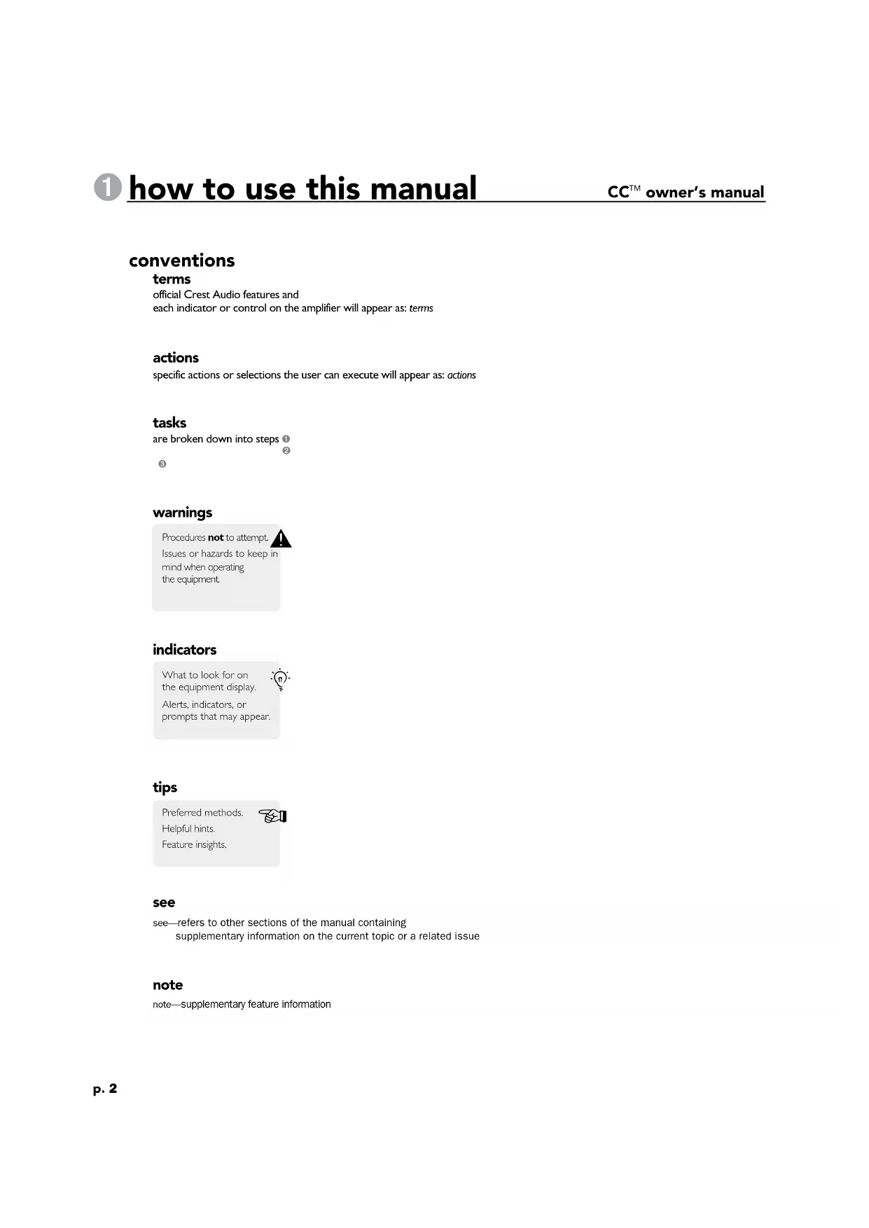
conventions
terms
official Crest Audio features and each indicator or control on the amplifier will appear as: terms
actions
specific actions or selections the user can execute will appear as: actions
tasks
are broken down into steps ① ② ③
warnings
Procedures not to attempt. Issues or hazards to keep in mind when operating the equipment.

indicators
What to look for on the equipment display. Alerts, indicators, or prompts that may appear.

tips
Preferred methods. Helpful hints. Feature insights.

see
see—refers to other sections of the manual containing supplementary information on the current topic or a related issue
note
note—supplementary feature information
welcome
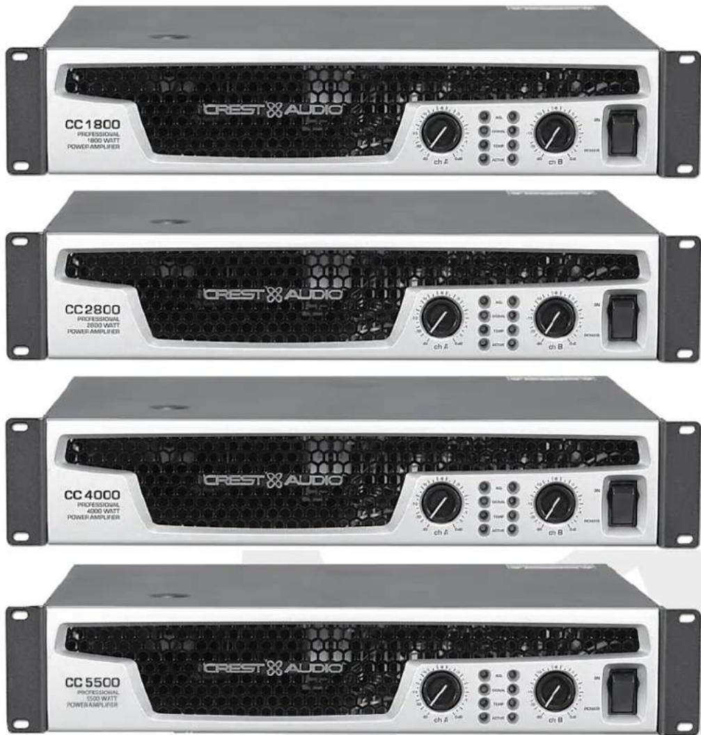
Congratulations on your purchase of a Crest Audio CC ^™ Series power amplifier. Designed for years of reliable, flawless operation under rigorous use. The Crest CC Series amplifiers offer the sonic superiority and unsurpassed reliability for which Crest Audio is famous, while remaining surprisingly compact. Advanced technology and extensive protection circuitry allow operation with greater efficiency into difficult loads and power conditions. The ACL ^™ (Automatic Clip Limiting) circuit ensures trouble-free operation into loads as low as 2 ohms. The Automatic Clip Limiting circuits protect drivers and ensure that sonic integrity is maintained, even in extreme overload conditions. Crest Audio's high-efficiency designs use tunnel-cooled heat sinks and variable speed DC fans. This cooling topology maintains a lower overall operating temperature, resulting in longer output transistor life. Model CC 5500, CC 4000, CC 2800, and CC 1800 power amplifiers use Crest Audio's innovative "Power Density" circuitry and packaging.
For your safety, read the important precautions section, as well as input, output, and power connection sections.

unpacking
Upon unpacking, inspect the amplifier. If you find any damage, notify your supplier immediately. Only the consignee may institute a claim with the carrier for damage incurred during shipping. Be sure to save the carton and all packing materials. Should you ever need to ship the unit back to Crest Audio, one of its offices, service centers, or the supplier, use only the original factory packing. If the shipping carton is unavailable, contact Crest to obtain a replacement.
For replacement
packaging, call Crest
Audio's
Customer Service
Department directly
see—service and support

mounting
CC Series amplifiers will mount in standard 19" racks. Rear mounting ears are also provided for additional support, which is recommended in non-permanent installations like mobile or touring sound systems. Because of the cables and connectors on the rear panel, a right angle or offset screwdriver or hex key will make it easier to fasten the rear mounting ears to the rails.
connecting power
CC Series amplifier power requirements are rated at 1/8^th power (typical music conditions) and 1/3^rd power (extreme music conditions). The maximum power current draw rating is limited only by the front panel circuit breaker. Consult the specifications in the Appendices section for figures on the current that each amplifier will demand. Make sure the mains voltage is correct and is the same as that printed on the rear of the amplifier. Damage caused by connecting the amplifier to improper AC voltage is not covered by any warranty. Unless otherwise specified when ordered, Crest amplifiers shipped to customers are configured as follows:
When connecting the CC 5500 to 220-240 AC supply, consult with supply authority as needed to insure impedance Zsysmax equal to or less than 0.08+0.05j.
Always turn off and
disconnect the amplifier
from mains voltage before
making audio connections.
Also, as an extra precaution,
have the attenuators turned
down during power-up.

Option I North America
120VAC / 60 Hz
Option 2 Europe, Asia
230VAC / 50 Hz
Option 3 Australia
240VAC / 50 Hz
Option 4 South America
120VAC / 60 Hz or 240VAC / 50 Hz
CC 5500- When connecting this unit to 220-240 AC supply, consult with supply authority as needed to insure impedance Zsysmax equal to or less than 0.08+0.05j.
cooling requirements
The CC ^™ Series amplifiers use a forced-air cooling system to maintain a low, even operating temperature. Air is drawn into the amplifier by fan(s) on the rear panel, courses through the cooling fins of the tunnel-configured channel heat sink(s), and then exhausts through the front panel grille. If a heat sink gets too hot, its sensing circuit will open the output relay, disconnecting the load from that particular channel. The CC 1800 utilizes one common heat sink and a single fan, but retains the separate circuitry. It is important to have an adequate air supply at the back of the amplifier and enough space around the front of the amplifier to allow the cooling air to escape. If the amp is rack mounted, do not use doors or covers on the front of the rack; the exhaust air must flow without resistance. If you are using racks with closed backs, use fans on the rear rack panel to pressurize the rack and ensure an ample air supply.
Make certain that there is enough space around the front and rear of the amplifier to allow the heated air to escape.
suggestion: In racks with closed backs allow at least one standard-rack-space opening for every four amps.


operating precautions
Make sure the mains voltage is correct and is the same as that printed on the rear of the amplifier. Damage caused by connecting the amplifier to improper AC voltage is not covered by any warranty. See the Connecting Power section for more information on voltage requirements.
Although the CC Series amplifiers have AUTORAMP ^™ circuitry, which raises the signal level gradually after the output relay closes, it is always a good idea to have the gain controls turned down during power-up to prevent speaker damage if there is a high signal level at the inputs. Whether you buy or make them, use good-quality connections, input cables and speaker cables, along with good soldering technique, to ensure trouble-free operation. Most intermittent problems are caused by faulty cables.
Consult the Wire Gauge Charts to determine proper gauges for different load impedances and cable lengths. Remember that cable resistance robs amplifier power in two ways: power lost directly to resistance ( R loss), and by increasing the impedance of the load presented to the amplifier, thereby decreasing the power demanded of the amplifier. Also make sure the mode switch is correctly set for the desired application. See Sections on Stereo, Parallel and Bridged Mono Operation for more information.
Always turn off and disconnect the amplifier from mains voltage before making audio connections. Also, as an extra precaution, turn the attenuators down during power-up.

connecting inputs
Input connections are made via the 3-pin XLR (pin 2+) or 6.3 mm plug "Combi" connectors on the rear panel of the amplifier. The inputs are actively balanced. The input overload point is high enough to accept the maximum output level of virtually any signal source.
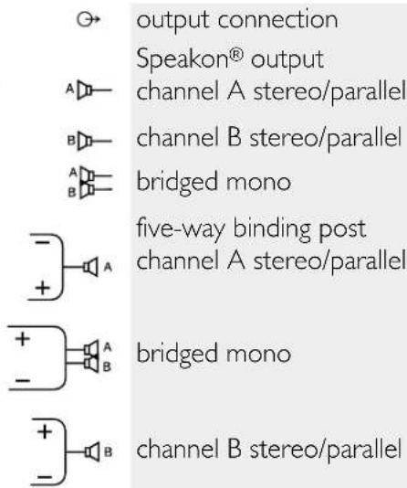
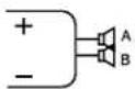
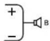
connecting outputs
All models have two output (speaker) connections per channel. Cables can be connected with banana plugs, spade lugs, or bare wire to the five-way binding posts. The preferred method is connection via the Speakon connectors.
③ features overview
CC ^TM owner's manual
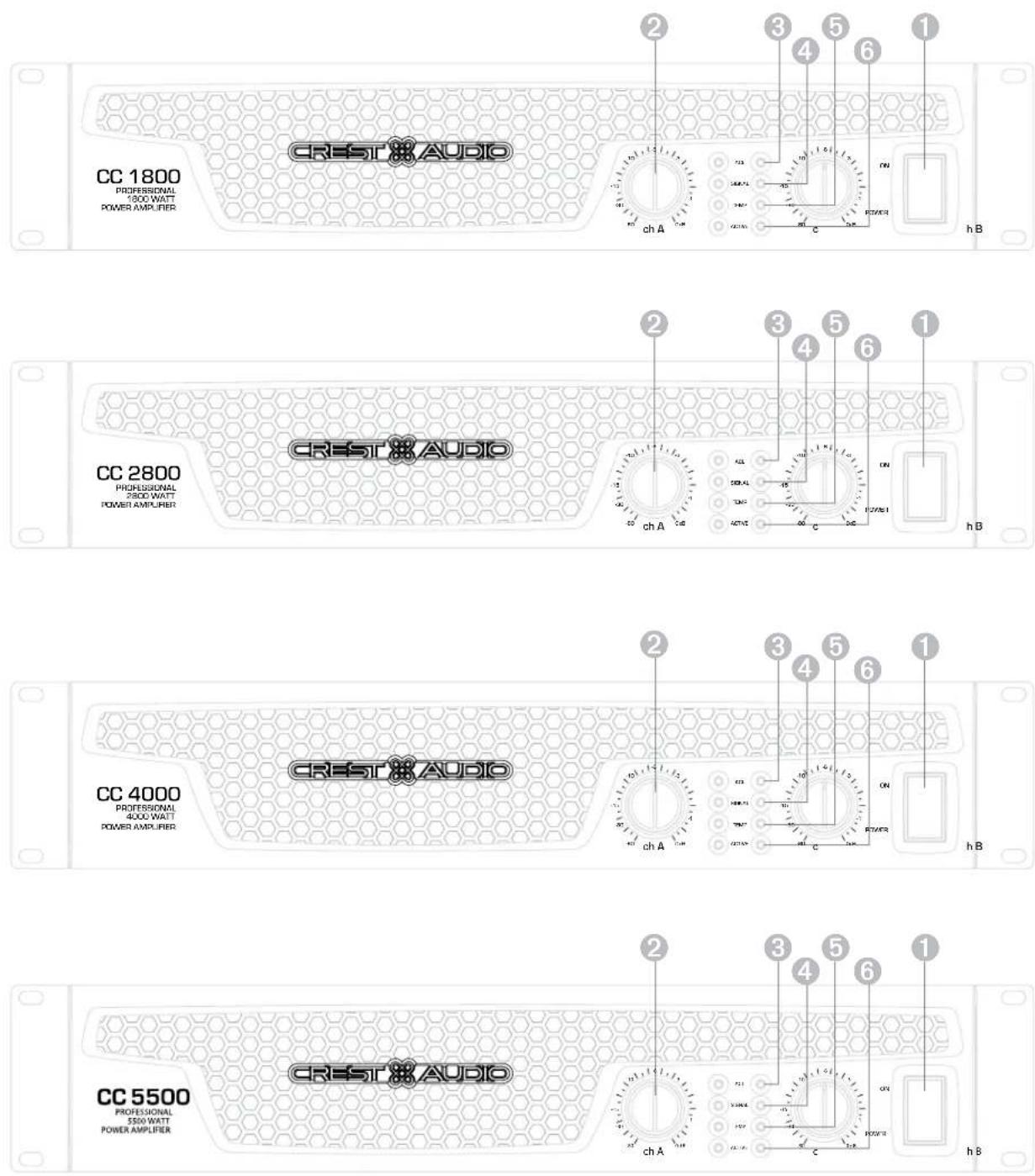
front panel
switches and controls
① AC Power Switch/Circuit Breaker
The CC Series amplifiers have a combination AC switch/circuit breaker on the front panel. If the switch shuts off during normal use, push it back to the ON position once. If it will not stay on, the amplifier needs servicing.
② Input Attenuators
Whenever possible, set the attenuators fully clockwise to maintain optimum system headroom. The input attenuator controls (one for channel A, one for channel B) located at the front panel adjust gain for their respective amplifier channels in all modes. See the specifications at the end of this manual for standard voltage gain and input sensitivity information.
The power only breaks one side of the AC mains. Hazardous energy may be present in the enclosure when the power switch is in the off position.

When operating in the bridged mode, both attenuators must be in the same position so the speaker load will be equally shared between the channels. See the section on Bridged Mono Operation for more information and precautions.

indicators
CC Series amplifiers feature four front panel LED indicators per channel: ACL™ (Automatic Clip Limiting), Signal, Temp, and Active. These LED indicators inform the user of each channel's operating status and warn of possible abnormal conditions.
③ ACL LED
A channel's ACL LED will light at the onset of clipping. If the LED's are flashing quickly and intermittently, the channel is just at the clip threshold, while a steady, bright glow means the amp is clip limiting, or reducing gain to prevent severely clipped waveforms reaching the loudspeakers. See the Automatic Clip Limiting section for more information. During initial power up the ACL LED will light indicating that the AUTORAMP ^™ gain reduction circuitry is activated. This will prevent sudden signal bursts when the speaker relays are closed.
④ Signal LED
This LED lights when its channel produces an output signal of about 4 volts RMS or more (0.1 volt or more at the input, with 0 dB attenuation and standard x40 voltage gain). It is useful in determining whether a signal is reaching and being amplified by the amplifier.
⑤ Temp LED
The Temp LED lights to indicate that the channel's output relay is open, disconnecting the speaker(s) due to an overheating condition. Once the channel temperature has returned to safe operating conditions the LED will turn off, the channel's output relay will close, and the speaker(s) will be reconnected.
⑥ Active LED
The Active LED indicates that its channel's output relay is closed and the channel is operational. It lights under normal operation and remains on even when the channel is in Automatic Clip Limiting or ACL gain reduction. These are protection features which leave the output relay closed. If the Active LED goes off, there is no signal at the output connectors.
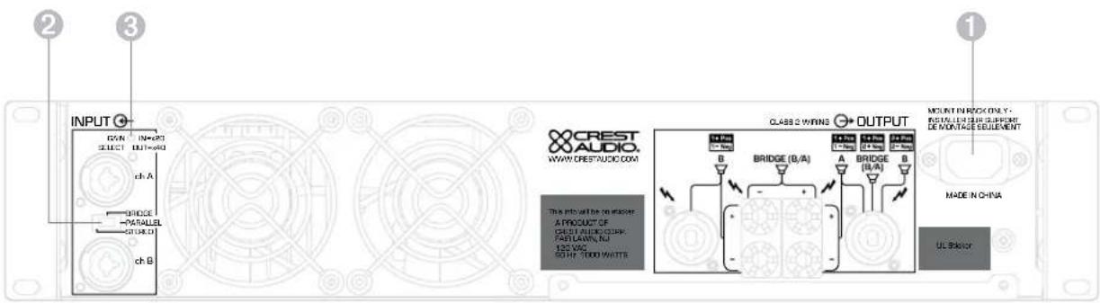
rear panel legend
rear panel
① IEC power connector
Accepts a standard IEC terminated power cable
② Mode Select Switch
The rear panel Mode Select Switch determines whether the amplifier is in the stereo, parallel, or bridged mono mode. Do not operate the Mode Select Switch with the amplifier powered on. See the sections on Stereo and Bridged Mono Mode for more information.
③ Gain Select Switch
The rear panel Gain Select Switch determines whether the amplifier has an overall gain of 40 (32 dB) or a gain of 20 (26 dB). The out position will select x40 while the in position will select x20.
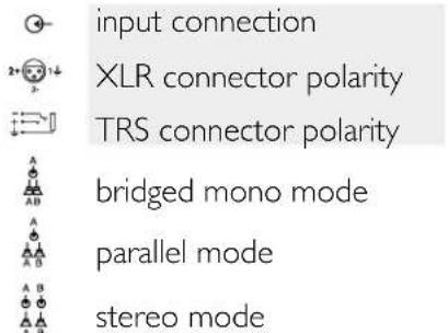
stereo
For stereo (dual channel) operation, turn the amplifier off and set the mode select switch to the stereo position. In this mode, both channels operate independently of each other, with their input attenuators controlling their respective levels. Thus, a signal at channel A's input produces an amplified signal at channel A's output, while a signal at channel B's input produces an amplified signal at channel B's output.
parallel
For parallel (dual-channel/single input) operation, turn the amplifier off and set the mode switch in the parallel position; both amplifier channels are then driven by the signal at channel A's input. No jumper wires are needed. Output connections are the same as in the stereo mode. Channel A's and channel B's input connectors are strapped together to allow patching to another amplifier. Both input attenuators remain active, allowing you to set different levels for each channel. Power and other general performance specifications are the same as in the stereo mode.
bridged mono
Both amplifier channels can be bridged together to make a very powerful single-channel monaural amplifier. Use extreme caution when operating in the bridged mode; potentially lethal voltage may be present at the output terminals. To bridge the amplifier, turn the amplifier off and slide the rear panel amplifier mode select switch to the bridge position. Apply the signal to channel A's input and connect the speakers across the hot outputs which are either the "+" binding posts of channels A and B. Alternately connect across pins "I+POS" and "2+NEG" of the channel A Speakon® connector. As with parallel operation, both input connectors are strapped together to drive the input of another amplifier.
Unlike the stereo and parallel modes, in which one side of each output is at ground, in the bridged mode both sides are hot. Channel A's side is the same polarity as the input. The minimum nominal load impedance in the bridged mode is 4 ohms which is equivalent to driving both channels at 2 ohms. Driving bridged loads of less than 4 ohms will activate the ACL circuitry resulting in a loss of power, and may also cause a thermal overload.
When operating in the bridged mode, both attenuators must be in the same position so the speaker load will be equally shared between the channels.


protection features
CC ^TM owner's manual
CC Series amplifiers incorporate several circuits to protect both themselves and loudspeakers under virtually any situation. Crest Audio has attempted to make the amplifiers as foolproof as possible by making them immune to short and open circuits, mismatched loads, DC voltage, and overheating. If a channel goes into the Automatic Clip Limiting or ACL ^™ gain reduction mode, the speaker load remains connected, but clipping percentage or output power are instantly reduced. When a problem occurs that causes a channel to go into a protection mode, the Temp LED for that channel will glow. DC voltage on the output, excessive subsonic frequencies, or thermal overload will cause the channel's output relay to disconnect the speaker load until the problem is corrected or the amplifier cools down.
automatic clip limiting (ACL)
Any time a channel is driven into hard, continuous clipping, the clip limiter circuit will automatically reduce the channel gain to a level just slightly into clipping, guarding the speakers against the damaging high power continuous square waves that may be produced. Situations that may activate the clip limiter include uncontrolled feedback, oscillation, or an improper equipment setting or malfunction upstream from the amplifier. Normal program transients will not trigger the clip limiter; only steady, excessive clipping will. The ACL LED will glow brightly and continuously when limiting occurs.
IGM™ impedance sensing
CC Series amplifiers feature innovative circuitry that allows safe operation into any load. When an amplifier sees a load that overstresses the output stage, the Instantaneous Gain Modulation (IGM) circuit adjusts the channel gain to a safe level. This method of output stage protection is far superior to conventional, brute force type limiting found on other amplifiers. The IGM circuit is sonically transparent in normal use and unobtrusive when activated.
thermal protection
The internal fans will keep the amplifier operating well within its intended temperature range under all normal conditions. If a channel's heat sink temperature reaches 75^ C, which may indicate an obstructed air supply, that channel will protect itself independently by disconnecting its load and shutting down until it has cooled. During this time, the channel's Temp LED will glow, the Active LED will go out, the ACL LEDs will stay lit and the cooling fans will run at high speed. The CC 1800 utilizes one common heat sink and single fan, but retains the separate circuitry.
short circuit
If an output is shorted, the IGM and thermal circuits will automatically protect the amplifier. The IGM circuit senses the short circuit as an extremely stressful load condition and attenuates the signal, protecting the channel's output transistors from over current stress. If the short circuit remains, the channel will eventually thermally protect itself by disconnecting the load.
DC voltage protection
If an amplifier channel detects DC voltage or subsonic frequencies at its output terminals, its output relay will immediately open to prevent loudspeaker damage.
turn-on/turn-off protection
At power-up, the amplifier stays in the protect mode, with outputs disconnected, for approximately six seconds while the power supplies charge and stabilize. While the output relays are open, the ACL LEDs light. When power is removed, the speaker loads immediately disconnect so that no thumps or pops are heard.
AUTORAMP™ signal control
Whenever a CC Series amplifier powers up or comes out of a protect mode, the AUTORAMP circuit activates. While the speakers are disconnected, the AUTORAMP circuit fully attenuates the signal. After the output relay closes, the signal slowly and gradually raises up to its set level. The AUTORAMP Signal Control circuit has some important advantages over conventional instant-on circuits:
- If a signal is present during power-up (or when coming out of protect), the speakers are spared a sudden, potentially damaging burst of audio power.
- Because the gain is reduced until after the output relay closes, no arcing occurs at the contacts, thereby extending their useful life.
speaker protection
All loudspeakers have electrical, thermal and physical limits that must be observed to prevent damage or failure. Too much power, low frequencies applied to high frequency drivers, severely clipped waveforms, and DC voltage can all be fatal to cone and compression drivers. The Crest Audio CC Series amplifiers automatically protect speakers from DC voltages and subsonic signals. For more information, see the section on Protection Features. Mid- and high-frequency speakers, especially compression drivers, are highly susceptible to damage from overpowering, clipped waveforms, or frequencies below their rated passband. Be extremely careful that the low and mid bands of an electronic crossover are connected to the correct amplifiers and drivers and not accidentally connected to those for a higher frequency band. The amplifier's clipping point is its maximum peak output power, and some of the higher power Crest Audio CC Series amplifiers can deliver more power than many speakers can safely handle. Be sure the peak power capability of the amplifier is not excessive for your speaker system.
To ensure that the speakers never receive excessive power and that the amplifier never clips, use a properly adjusted external limiter (or a compressor with a ratio of 10:1 or higher) to control power output. In systems with active electronic crossovers, use one for each frequency band. The clip limiter will automatically limit the duration of continuous square waveforms applied to the speakers. The amplifier will, however, allow normal musical transient bursts to pass. Some speaker systems are packaged with processors that have power limiting circuits and should not require additional external limiting.
Fuses may also be used to limit power to speaker drivers, although as current-limiting (rather than voltage-limiting devices) they are an imperfect solution. As the weakest links, fuses only limit once before needing replacement. Some poor quality fuses have a significant series resistance that could degrade the amplifier's damping of the speaker's motion and may even deteriorate the system's sound quality. If you elect to use fuses, check with the speaker manufacturer to determine the proper current rating and time lag required.
Do not drive any low-frequency speaker enclosure with frequencies lower than its own tuned frequency. The reduced acoustical damping could cause a ported speaker to bottom out even at moderate power. Consult the speaker system specifications to determine its frequency limits.
amplifier maintenance and user responsibility
A CC Series amplifier requires no routine maintenance and should never need any internal adjustment during its lifetime. Your CC Series amplifier is very powerful and can be potentially dangerous to loudspeakers and humans alike. It is your responsibility to read the Important Precautions section in the front of this manual, and to make sure that the amplifier is installed, wired and operated properly. Many loudspeakers can be easily damaged or destroyed by overpowering, especially with the high power available from a bridged amplifier. Read the Speaker Protection section and always be aware of the speaker's continuous and peak power capabilities.
support
In the unlikely event that your amplifier develops a problem, it must be returned to an authorized distributor, service center, or shipped directly to our factory for service.
To obtain service, contact your nearest Crest Audio Service Center, Distributor, Dealer, or any of the worldwide Crest Audio offices. For those with Internet access, please visit the Crest Audio web site.
Because of the complexity of the design and the
risk of electrical shock, all repairs must be attempted only by qualified technical
personnel. If the unit needs
to be shipped back to the factory,
it must be sent in its original carton.
If improperly packed, your amplifier may be damaged.


contact us
customer service
phone 866.812.7378 USA
fax 601.486.1380 USA
email customerserve@crestaudio.com
technical support
phone 866.812.7378 USA
fax 601.486.1380 USA
email techserve@crestaudio.com
web site
www.crestaudio.com
Crest Audio Inc.
711 A Street
Meridian, MS 39301 USA
For replacement packaging, call Crest Audio's Customer Service.

1800
| Rated Power Bridge 4 ohms | 1850 watts @ 1 kHz at <0.1% T.I.L.D. |
| Rated Power (2 x 2 ohms) | 900 watts per channel @ 1 kHz <0.05% T.H.D. both channels driven |
| Rated Power (2 x 4 ohms) | 700 watts per channel @ 1 kHz at <0.05% T.H.D. both channels driven |
| Rated Power (2 x 8 ohms) | 450 watts per channel @ 1 kHz at <0.05% T.H.D. both channels driven |
| Rated Power (1 x 2 ohms) | 950 watts @ 1 kHz at <0.05% T.I.L.D. |
| Rated Power (1 x 4 ohms) | 775 watts @ 1 kHz at <0.05% T.H.D. |
| Rated Power (1 x 8 ohms) | 475 watts @ 1 kHz at <0.05% T.H.D. |
| Minimum Load Impedance | 2 ohms |
| Maximum RMS Voltage Swing | 73 volts |
| Frequency Response | 10 Hz - 100 kHz; +0, -3 dB at 1 watt |
| Power Bandwidth | 10 Hz - 50 kHz; +0, -3 dB at rated 4 ohm power |
| T.H.D. (2 x 2 ohms) | <0.2% @ 700 watts per channel from 20 Hz to 20 kHz |
| T.H.D. (2 x 4 ohms) | <0.1% @ 600 watts per channel from 20 Hz to 20 kHz |
| T.H.D. (2 x 8 ohms) | <0.1% @ 425 watts per channel from 20 Hz to 20 kHz |
| Input CMRR | > -75 dB @ 1 kHz |
| Voltage Gain | x40 (32 dB) x20 (26 dB) |
| Crosstalk | > -55 dB @ 1 kHz at rated power @ 8 ohms |
| Hum and Noise | > -106 dB, "A" weighted referenced to rated power @ 8 ohms |
| Slew Rate | > 35V/us |
| Damping Factor (8 ohms) | > 150:1 @ 20 Hz - 1 kHz at 8 ohms |
| Phase Response | +6 to - 12 degrees from 20 Hz to 20 kHz |
| Input Sensitivity (x40) | 1.32 volts +/- 3% for 1 kHz, 4 ohm rated power, 1.06 volts +/- 3% for 1 kHz, 2 ohm rated power |
| Input Impedance | 15 k ohms, balanced |
| Current Draw @ 1/8 power | 1,000 watts @ 2 ohms, 685 watts @ 4 ohms, 400 watts @ 8 ohms |
| Current Draw @ 1/3 power | 2,340 watts @ 2 ohms, 1,650 watts @ 4 ohms, 1,000 watts @ 8 ohms |
| Cooling | One back panel temperature dependant variable speed 80 mm DC fan |
| Controls | 2 front panel attenuators, rear panel Mode switches |
| Indicator LEDs | 2 ACLTM (automatic clip limiting), 2 Signal presence, 2 Active status, 2 Temp |
| Protection | Thermal, DC, turn-on bursts, subsonic, incorrect loads |
| Connectors | Combi XLR & 6.3 mm phone input, Speakon and 5-way Binding Post speaker output, 15 amp IEC mains connector |
| Construction | 16 ga, steel with cast front panel |
| Dimensions | 88.9 mm x 482.6 mm x 377.8 mm + 31.8 mm for rear support ears and connectors (3.5" x 19" x 14.875" + 1.25") |
| Net Weight | 14.8 kg (32.6 lbs.) |
| Gross Weight | 15.9 kg (35 lbs.) |
All power measurements made at 120 VAC, power transformer cold. 2 ohm power is time limited by magnetic circuit breaker.
2800
| Rated Power Bridge 4 ohms | 2,800 watts @ 1 kHz at <0.1% T.I.L.D. |
| Rated Power (2 x 2 ohms) | 1,400 watts per channel @ 1 kHz <0.05% T.H.D. both channels driven |
| Rated Power (2 x 4 ohms) | 965 watts per channel @ 1 kHz at <0.05% T.H.D. both channels driven |
| Rated Power (2 x 8 ohms) | 595 watts per channel @ 1 kHz at <0.05% T.I.L.D. both channels driven |
| Rated Power (1 x 2 ohms) | 1,850 watts @ 1 kHz at <0.1% T.I.L.D. |
| Rated Power (1 x 4 ohms) | 1,150 watts @ 1 kHz at <0.05% T.H.D. |
| Rated Power (1 x 8 ohms) | 665 watts @ 1 kHz at <0.05% T.I.L.D. |
| Minimum Load Impedance | 2 ohms |
| Maximum RMS Voltage Swing | 82 volts |
| Frequency Response | 10 Hz - 100 kHz; +0, -2.0 dB at 1 watt |
| Power Bandwidth | 10 Hz - 35 kHz; +0, -3 dB at rated 4 ohm power |
| T.H.D. (2 x 2 ohms) | <0.15 @ 1,150 watts per channel from 20 Hz to 20 kHz |
| T.H.D. (2 x 4 ohms) | <0.1% @ 880 watts per channel from 20 Hz to 20 kHz |
| T.H.D. (2 x 8 ohms) | <0.1% @ 560 watts per channel from 20 Hz to 20 kHz |
| Input CMRR | > -65 dB @ 1 kHz |
| Voltage Gain | x40 (32 dB) x20 (26 dB) |
| Crosstalk | > -65 dB @ 1 kHz at rated power @ 8 ohms |
| Hum and Noise | > -111 dB, "A" weighted referenced to rated power @ 8 ohms |
| Slew Rate | > 15V/μs |
| Damping Factor (8 ohms) | > 500:1 @ 20 Hz - 1 kHz |
| Phase Response | +5 to -15 degrees from 20 Hz to 20kHz |
| Input Sensitivity (x40) | 1.7 volts +/- 3% for 1 kHz, 4 ohm rated power, 1.36 volts +/- 3% for 1 kHz, 2 ohm rated power |
| Input Impedance | 15 k ohms, balanced |
| Current Draw @ 1/8 power | 1,250 watts @ 2 ohms, 880 watts @ 4 ohms, 570 @ 8 ohms |
| Current Draw @ 1/3 power | 2,905 watts @ 2 ohms, 2,220 watts @ 4 ohms, 1,355 watts @ 8 ohms |
| Cooling | Two back panel temperature dependant variable speed 80 mm DC fans |
| Controls | 2 front panel attenuators, rear panel Mode switches |
| Indicator LEDs | 2 ACLTM (automatic clip limiting), 2 Signal presence, 2 Active status, 2 Temp |
| Protection | Thermal, DC, turn-on bursts, subsonic, incorrect loads |
| Connectors | Combi XLR & 6.3 mm phone input, Speakon and 5-way Binding Post speaker output, 15 amp IEC mains connector |
| Construction | 16 ga, steel with cast front panel |
| Dimensions | 88.9 mm x 482.6 mm x 377.8 mm + 31.8 mm for rear support ears and connectors (3.5" x 19" x 14.875" - 1.25") |
| Net Weight | 18.05 kg (39.8 lbs.) |
| Gross Weight | 19.23 kg (42.4 lbs.) |
All power measurements made at 120 VAC, power transformer cold. 2 ohm power is time limited by magnetic circuit breaker.
4000
| Rated Power Bridge 4 ohms | 4,000 watts @ 1 kHz at <0.1% T.H.D. |
| Rated Power (2 x 2 ohms) | 2,000 watts per channel @ 1 kHz <0.1% T.H.D. both channels driven |
| Rated Power (2 x 4 ohms) | 1,350 watts per channel @ 1 kHz at <0.05% T.H.D. both channels driven |
| Rated Power (2 x 8 ohms) | 800 watts per channel @ 1 kHz at <0.05% T.H.D. both channels driven |
| Rated Power (1 x 2 ohms) | 2,550 watts @ 1 kHz at <0.1% T.H.D. |
| Rated Power (1 x 4 ohms) | 1,600 watts @ 1 kHz at <0.05% T.H.D. |
| Rated Power (1 x 8 ohms) | 900 watts @ 1 kHz at <0.05% T.H.D. |
| Minimum Load Impedance | 2 ohms |
| Maximum RMS Voltage Swing | 93 volts |
| Frequency Response | 10 Hz - 100 kHz; +0, -2 dB at 1 watt |
| Power Bandwidth | 10 Hz - 35 kHz; +0, -3 dB at rated 4 ohm power |
| T.H.D. (2 x 2 ohms) | <0.2% @ 1,475 watts per channel from 20 Hz to 20 kHz |
| T.H.D. (2 x 4 ohms) | <0.1% @ 1,150 watts per channel from 20 Hz to 20 kHz |
| T.H.D. (2 x 8 ohms) | <0.1% @ 700 watts per channel from 20 Hz to 20 kHz |
| Input CMRR | > -65 dB @ 1 kHz |
| Voltage Gain | x40 (32 dB) x20 (26 dB) |
| Crosstalk | > -65 dB @ 1 kHz at rated power @ 8 ohms |
| Hum and Noise | > -112 dB, "A" weighted referenced to rated power @ 8 ohms |
| Slew Rate | > 15V/us |
| Damping Factor (8 ohms) | > 500:1 @ 20 Hz - 1 kHz |
| Phase Response | +5 to -15 degrees from 20 Hz to 20 kHz |
| Input Sensitivity (x40) | 1.88 volts +/- 3% for 1 kHz, 4 ohm rated power, 1.62 volts +/- 3% for 1 kHz power |
| Input Impedance | 15 k ohms, balanced |
| Current Draw @ 1/8 power | 1,825 watts @ 2 ohms, 1,185 watts @ 4 ohms, 720 @ 8 ohms |
| Current Draw @ 1/3 power | 4,535 watts @ 2 ohms, 2,975 watts @ 4 ohms, 1,835 watts @ 8 ohms |
| Cooling | Two back panel temperature dependant variable speed 80 mm DC fans |
| Controls | 2 front panel attenuators, rear panel Mode switches |
| Indicator LEDs | 2 ACLTM (automatic clip limiting), 2 Signal presence, 2 Active status, 2 Ter |
| Protection | Thermal, DC, turn-on bursts, subsonic, incorrect loads |
| Connectors | Combi XLR & 6.3 mm phone input. Speakon and 5-way Binding Post sp |
| amp IEC mains connector | |
| Construction | 16 ga. steel with cast front panel |
| Dimensions | 88.9 mm x 482.6 mm x 377.8 mm + 31.8 mm for rear support cars and co |
| (3.5" x 19" x 14.875" + 1.25") | |
| Net Weight | 19.64 kg (43.3 lbs.) |
| Gross Weight | 20.8 kg (45.8 lbs.) |
All power measurements made at 120 VAC, power transformer cold. 2 ohm power is time limited by magnetic circuit breaker.
5500
| Rated Power Bridge 4 ohms | 5,550 watts @ 1 kHz at <0.1% T.H.D. |
| Rated Power (2 x 2 ohms) | 2,750 watts per channel @ 1 kHz <0.05% T.H.D. both channels driven. |
| Rated Power (2 x 4 ohms) | 1,800 watts per channel @ 1 kHz at <0.05% T.I.D. both channels driven |
| Rated Power (2 x 8 ohms) | 1,150 watts per channel @ 1 kHz at <0.05% T.H.D. both channels driven |
| Rated Power (1 x 2 ohms) | 3,600 watts @ 1 kHz at <0.05% T.H.D. |
| Rated Power (1 x 4 ohms) | 2,200 watts @ 1 kHz at <0.05% T.I.D. |
| Rated Power (1 x 8 ohms) | 1,280 watts @ 1 kHz at <0.05% T.H.D. |
| Minimum Load Impedance | 2 ohms |
| Maximum RMS Voltage Swing | 115 volts |
| Frequency Response | 10 Hz - 40 kHz; -0, -3 dB at 1 watt |
| Power Bandwidth | 10 Hz - 30 kHz; +0, -3 dB at rated 4 ohm power |
| T.H.D. (2 x 2 ohms) | <0.2% @ 1,900 watts per channel from 20 Hz to 20 kHz |
| T.H.D. (2 x 4 ohms) | <0.05% @ 1,525 watts per channel from 20 Hz to 20 kHz |
| T.H.D. (2 x 8 ohms) | <0.05% @ 1,000 watts per channel from 20 Hz to 20 kHz |
| Input CMRR >-63 dB @ 1 kHz | |
| Voltage Gain x 40 (32 dB), x 20 (26 dB) | |
| Crosstalk >67 dB @ 1 kHz at 700 watts @ 4 ohms | |
| Hum and Noise >-110 dB, "A" weighted referenced to rated power @ 8 ohms | |
| Damping Factor (8 ohms) | >400:1 @ 20 Hz - 1 kHz |
| Phase Response | +5 to -55 degrees from 20 Hz to 20 kHz |
| Input Sensitivity | 2.18 volts +/- 3% for 1 kHz. 4 ohm rated power, 1.89 volts +/- 3% for 1 kHz. 2 ohm rated power |
| Input Impedance | 15 k ohms balanced, 7.5 k ohms unbalanced |
| Current Draw @ 1/8 power | 2,640 watts @ 2 ohms, 1,740 watts @ 4 ohms, 1,140 watts @ 8 ohms |
| Current Draw @ 1/3 power | 5,920 watts @ 2 ohms. 4,150 watts @ 4 ohms, 2,690 watts @ 8 ohms |
| Cooling | Two back panel temperature dependent variable speed 80 mm DC fans |
| Controls | 2 front panel attenuators, rear panel Gain and Mode switches |
| Indicator LEDs | 2 ACL (clip limiting), 2 Signal presence, 2 Active status, 2 Temp |
| Protection | Thermal, DC, turn-on bursts, subsonic, incorrect loads. |
| ConnectorsAC power plug (USA only) | Combi 1⁄2" & XLR inputs, Speakon® and binding post speaker output, NFMA #L5-30P |
| Construction | 16 ga. steel with cast front panel |
| Dimension(3.5"x19"x 14.875" + 1.25"). | 88.9mm x 482.6mm x 377.8mm + 31.8mm for rear support ears and connectors |
| Net Weight | 21.32 kg. (47 lbs.) |
| Gross Weight | 22.9 kg. (50.5 lbs.) |
| stranded cable length | wire gauge | power loss | ||
| 8 Ω load | 4 Ω load | 2 Ω load | ||
| 2 meters | 0.3mm2 | 2.9% | 5.6% | 10.8% |
| 0.5 | 1.74 | 3.4 | 6.7 | |
| 0.75 | 1.16 | 2.3 | 4.5 | |
| 1.5 | 0.58 | 1.16 | 2.3 | |
| 2.5 | 0.35 | 0.70 | 1.39 | |
| 4.0 | 0.22 | 0.44 | 0.87 | |
| 5 meters | 0.5mm2 | 4.3% | 8.2% | 15.5% |
| 0.75 | 2.9 | 5.6 | 10.8 | |
| 1.5 | 1.45 | 2.9 | 5.6 | |
| 2.5 | 0.87 | 1.74 | 3.4 | |
| 4 | 0.55 | 1.09 | 2.2 | |
| 6 | 0.37 | 0.73 | 1.45 | |
| 10 meters | 0.5mm2 | 8.24% | 5.5% | 28% |
| 0.75 | 5.6 | 10.8 | 19.9 | |
| 1.5 | 2.9 | 5.6 | 10.8 | |
| 2.5 | 1.74 | 2.9 | 6.7 | |
| 4 | 1.09 | 1.74 | 4.3 | |
| 6 | 0.73 | 1.09 | 2.9 | |
| 30 meters | 0.75mm2 | 15.5% | 0.73% | 45% |
| 1.5 | 8.2 | 15.5 | 28 | |
| 2.5 | 5.1 | 9.8 | 18.2 | |
| 4 | 3.2 | 6.3 | 12.0 | |
| 6 | 2.2 | 4.3 | 8.2 | |
| 10 | 1.31 | 2.6 | 5.1 | |
| stranded cable length | wire gauge | power loss | ||
| 8 Ω load | 4 Ω load | 2 Ω load | ||
| 5 feet | 18AWG | 0.81% | 1.61% | 3.2% |
| 16 | 0.51 | 1.02 | 2.0 | |
| 14 | 0.32 | 0.61 | 1.28 | |
| 12 | 0.20 | 0.40 | 0.80 | |
| 10 | 0.128 | 0.25 | 0.51 | |
| 10 feet | 18AWG | 1.61% | 3.2% | 6.2% |
| 16 | 1.02 | 2.0 | 4.0 | |
| 14 | 0.64 | 1.28 | 2.5 | |
| 12 | 0.40 | 0.80 | 1.60 | |
| 10 | 0.25 | 0.51 | 1.01 | |
| 40 feet | 18AWG | 6.2% | 11.9% | 22% |
| 16 | 4.0 | 7.7 | 14.6 | |
| 14 | 2.5 | 5.0 | 9.6 | |
| 12 | 1.60 | 3.2 | 6.2 | |
| 10 | 1.01 | 2.0 | 4.0 | |
| 8 | 0.60 | 1.20 | 2.4 | |
| 80 feet | 18AWG | 11.9% | 22% | 37% |
| 16 | 7.7 | 14.6 | 26 | |
| 14 | 5.0 | 9.6 | 17.8 | |
| 12 | 3.2 | 6.2 | 11.8 | |
| 10 | 2.0 | 4.0 | 7.7 | |
| 8 | 1.20 | 2.4 | 4.7 | |
Stereo/Parallel Kanal A

Stereo/Parallel Kanal B

Bridged Mono
Stereo/Parallel Kanal A
Bridged Mono
Stereo/Parallel Kanal B
Stereo
Informations services
email customerserve@crestaudio.com
Service technique
Téléphone 866.812.7378 USA
Fax 601.486.1380 USA
email techserve@crestaudio.com
web site
www.crestaudio.com
email customerserve@crestaudio.com
Effective Date: January, 2011
WHAT THIS WARRANTY COVERS
Your Crest Audio Warranty covers defects in material and workmanship in Crest Audio products purchased in the U.S.A.
WHAT THIS WARRANTY DOES NOT COVER
The Warranty does not cover: (1) damage caused by accident, misuse, abuse, improper installation or operation, rental, product modification or neglect; (2) damage occurring during shipment; (3) damage caused by repair or service performed by persons not authorized by Crest Audio; (4) products on which the serial number has been altered, defaced or removed; (5) products not purchased directly from Crest Audio or from an Authorized Crest Audio Dealer; (6) normal wear and tear.
WHO THIS WARRANTY PROTECTS
This Warranty protects only the original purchaser of the product and is not transferable.
HOW LONG THIS WARRANTY LASTS
The Warranty begins on the date of purchase by the original retail purchaser. The duration of the Warranty is as follows:
| Product Category Duration | |
| Amplifiers 5 years | |
| Consoles 5 years | |
| Signal Processing 2 years (+1 year)* | |
| Enclosures 3 years (+1 year)* | |
| Crest Performance** 2 years (+1 year)* |
[*One year additional warranty period applicable if optional Warranty Registration Card is completed and returned to Crest Audio by original purchaser within 90 days of purchase.]
[**Includes all products sold under the "Crest Performance" brand including amplifiers, consoles, signal processing, enclosures and any other product category.]
WHAT CREST AUDIO WILL DO
We will repair or replace (at Crest Audio's discretion) products covered by warranty at no charge for labor or materials. If the product or component must be shipped to Crest Audio for warranty service, the consumer must pay initial shipping charges. If the repairs are covered by warranty, Crest Audio will pay the return shipping charges.
HOW TO GET WARRANTY SERVICE
(1) Take the defective item and your sales receipt or other proof of date of purchase to your Authorized Crest Audio Dealer or Authorized Crest Audio Service Center. OR (2) Ship the defective item, prepaid, to Crest Audio, 412 Highway 11 & 80 East, Meridian, MS 39301. Include a detailed description of the problem, together with a copy of your sales receipt or other proof of date of purchase as evidence of warranty coverage. Also provide a complete return address.
LIMITATION OF IMPLIED WARRANTIES
ANY AND ALL IMPLIED WARRANTIES, INCLUDING WARRANTIES OF MERCHANTABILITY AND FITNESS FOR A PARTICULAR PURPOSE, ARE LIMITED IN DURATION TO THE LENGTH OF THIS WARRANTY. Some states do not allow limitations on how long an implied warranty lasts, so the above limitation may not apply to you.
EXCLUSIONS OF DAMAGES
CREST AUDIO'S LIABILITY FOR ANY DEFECTIVE PRODUCT IS LIMITED TO THE REPAIR OR REPLACEMENT OF THE PRODUCT, AT CREST AUDIO'S OPTION. IF WE ELECT TO REPLACE THE PRODUCT, THE REPLACEMENT MAY BE A RECONDITIONED UNIT. CREST AUDIO SHALL NOT BE LIABLE FOR DAMAGES BASED ON INCONVENIENCE, LOSS OF USE, LOST PROFITS, LOST SAVINGS, DAMAGE TO ANY OTHER EQUIPMENT OR OTHER ITEMS AT THE SITE OF USE, OR ANY OTHER DAMAGES WHETHER INCIDENTAL, CONSEQUENTIAL OR OTHERWISE, EVEN IF CREST AUDIO HAS BEEN ADVISED OF THE POSSIBILITY OF SUCH DAMAGES. Some states do not allow the exclusion or limitation of incidental or consequential damages, so the above limitation or exclusion may not apply to you.
This Warranty gives you specific legal rights, and you may also have other rights which vary from state to state. If you have any questions about this warranty or service received or if you need assistance in locating an Authorized Service Center, please contact Crest Audio at (866) 812-7378 and ask for the service department.
NOTES:
NOTES:
NOTES:
U.S.A. and Canada customer warranty registration.
5 Year Product Warranty Registration Card

On behalf of everyone at Crest Audio, we thank you for purchasing this Crest Product. By returning this warranty card you will receive an additional year of warranty on the following products: Crest Audio signal processing equipment, Crest Audio speakers and enclosures and all Crest Performance products. To save time, submit your warranty registration online at www.crestaudio.com.
Company:
Address:
City: State: Zip:
Country:
Phone: Age:
FAX:
e-mail:
Model:
Serial number:
Dealer name:
Dealer city: Dealer state:
You are: □ sound company
□ facility owner/manager
□DJ
□ broadcaster
installer
musician
Where is the amplifier used?
□ touring/mobile
house of worship
□ club
□ theater
other
How is it used?
house PA
□ monitor PA
□ mobile DJ
instrument amp
□ paging/BGM
□ studio monitor
Why did you purchase this amplifier?
amp
replacement/upgrade
□ add to
isting system
□ new system
Where did you learn about Crest?
□ magazine
salesperson
□ business associate
□ competitor
Is this your first Crest product?
□ yes
no
Were you give
a demonstration?
□ yes
no
Why did you buy Crest?
□ durability
□ sound quality
price
features
□ past experience
reputation
Have you visited our Internet web site www.crestaudio.com?
□ yes
no
What new products should Crest develop?
What magazines do you regularly read?
May we send you more information about Crest power amplifiers?
□ yes
not now
When will you purchase your next amplifier?
6 months
□ I year
□ 2 years
longer
May we send you more information about Crest mixing consoles?
□ yes
not now
When will you purchase your next console?
6 months
□ I year
□ 2 years
longer
What other brands of amplifier/console are you using?
Comments:

412 Highway 11&80 East - Meridian, MS 39301
TEL 866-812-7378
FAX 601-486-1361
http://www.crestaudio.com
Place
Stamp
Here

CREST
AUDIO
412 Highway 11& 80 East
Meridian, MS 39301