WTP B40 - Battery charger Palmer - Free user manual and instructions
Find the device manual for free WTP B40 Palmer in PDF.

| Product type | Low-voltage power distribution system for pedalboard |
| Model | Palmer PEDALBAY 40 (WTP B40) |
| Number of outputs | 8 (6 fixed 9 V DC outputs + 2 switchable 9/12/18 V DC outputs) + 1 thru output |
| Output connectors | 2.1 x 5.5 mm low-voltage jacks (coaxial) |
| Output voltage | 9 V DC (fixed outputs) or 9/12/18 V DC (switchable outputs), center positive |
| Maximum output current | 2 A total, 300 mA per fixed output, 500 mA per switchable output |
| Power supply | External power adapter 100-240 V AC, 50/60 Hz, output 12 V DC / 2 A |
| Protection circuit | Short-circuit and overload per output, red LED in case of fault |
| Controls | On/off switch, two 9/12/18 V switches |
| Display | Power LED, 8 bicolor LEDs (green = OK, red = fault) |
| Mounting | Integration into Palmer PEDALBAY 40 pedalboard (screws and nuts included) |
| Housing material | Powder-coated / anodized aluminum, black |
| Dimensions (L x H x P) | 450 x 24 x 50 mm |
| Weight | 0.65 kg |
| Operating temperature | 0 °C to 40 °C |
| Relative humidity | Less than 80 % (non-condensing) |
| Included accessories | Power adapter, 14 DC cables (9 of 60 cm, 5 of 16 cm), nuts, protection bar, Velcro strap, cable ties |
| Maintenance | Clean with a dry cloth; do not open the device |
| Safety | Do not expose to water or heat sources; disconnect during thunderstorms |
| Warranty | See Adam Hall website for terms |
Frequently Asked Questions - WTP B40 Palmer
User questions about WTP B40 Palmer
0 question about this device. Answer the ones you know or ask your own.
Ask a new question about this device
Download the instructions for your Battery charger in PDF format for free! Find your manual WTP B40 - Palmer and take your electronic device back in hand. On this page are published all the documents necessary for the use of your device. WTP B40 by Palmer.
USER MANUAL WTP B40 Palmer
natural_image
Two black industrial control panels with labeled ports and buttons, one showing a 12V/2A output stage (no readable text or symbols beyond branding)WTP B40
POWERBAR – POWER SUPPLY
WITH 8 OUTPUTS FOR PEDALBAY 40
PWTPB40
CONTENTS / INHALTSVERZEICHNIS / CONTENU / CONTENIDO /TREŚĆ / CONTENUTO
ENGLISH
SAFETY INFORMATION 3
INTRODUCTION
CONNECTIONS, OPERATING AND
DISPLAY ELEMENTS 5
INSTALLATION
TECHNICAL DATA 7
MANUFACTURER'S DECLARATIONS 8
DEUTSCH
SICHERHEITSHINWEISE
EINFÜHRUNG
We have designed this product to operate reliably over many years. Palmer® stands for this with its name and many years of experience as a manufacturer of high-quality audio products. Please read this User's Manual carefully, so that you can begin making optimum use of your Palmer® product quickly. You can find more information about Palmer® at our Internet site www.palmer-germany.com.
SAFETY INFORMATION
- Please read these instructions carefully.
- Keep all information and instructions in a safe place.
- Follow the instructions.
- Observe all safety warnings. Never remove safety warnings or other information from the equipment.
- Use the equipment only in the intended manner and for the intended purpose.
- Use only sufficiently stable and compatible stands and/or mounts (for fixed installations). Make certain that wall mounts are properly installed and secured. Make certain that the equipment is installed securely and cannot fall down.
- During installation, observ e the applicable safety regulations for your country.
- Never install and operate the equipment near radiators, heat registers, ovens or other sources of heat. Make certain that the equipment is always installed so that is cooled sufficiently and cannot overheat.
- Never place sources of ignition, e.g., burning candles, on the equipment.
- Ventilation slits must not be blocked.
- Keep a minimum distance of 20 cm around and above the device.
- Do not use this equipment in the immediate vicinity of water (does not apply to special outdoor equipment - in this case, observe the special instructions noted below. Do not expose this equipment to flammable materials, fluids or gases. Avoid direct sunlight!
- Make certain that dripping or splashed water cannot enter the equipment. Do not place containers filled with liquids, such as vases or drinking vessels, on the equipment.
- Make certain that objects cannot fall into the device.
- Use this equipment only with the accessories recommended and intended by the manufacturer.
- Do not open or modify this equipment.
- After connecting the equipment, check all cables in order to prevent damage or accidents, e.g., due to tripping hazards.
- During transport, make certain that the equipment cannot fall down and possibly cause property damage and personal injuries.
- If your equipment is no longer functioning properly, if fluids or objects have gotten inside the equipment or if it has been damaged in anot her way, switch it off immediately and unplug it from the mains outlet (if it is a powered device). This equipment may only be repaired by authorized, qualified personnel.
- Clean the equipment using a dry cloth.
- Comply with all applicable disposal laws in your country. During disposal of packaging, please separate plastic and paper/cardboard.
- Plastic bags must be kept out of reach of children.
- Please note that changes or modifications not expressly approved by the party responsible for compliance could void the user's authority to operate the equipment.
FOR EQUIPMENT THAT CONNECTS TO THE POWER MAINS
- CAUTION: If the power cord of the device is equipped with an earthing contact, then it must be connected to an outlet with a protective ground. Never deactivate the protective ground of a power cord.
- If the equipment has been exposed to strong fluctuations in temperature (for example, after transport), do not switch it on immediately. Moisture and condensation could damage the equipment. Do not switch on the equipment until it has reached room temperature.
- Before connecting the equipment to the power outlet, first verify that the mains voltage and frequency match the values specified on the equipment. If the equipment has a voltage selection switch, connect the equipment to the power outlet only if the equipment values and the mains power values match. If the included power cord or power adapter does not fit in your wall outlet, contact your electrician.
- Do not step on the power cord. Make certain that the power cable does not become kinked, especially at the mains outlet and/or power adapter and the equipment connector.
- When connecting the equipment, make certain that the power cord or power adapter is always freely accessible. Always disconnect the equipment from the power supply if the equipment is not in use or if you want to clean the equipment. Always unplug the power cord and power adapter from the power outlet at the plug or adapter and not by pulling on the cord. Never touch the power cord and power adapter with wet hands.
-
Whenever possible, avoid switching the equipment on and off in quick succession because otherwise this can shorten the useful life of the equipment.
-
IMPORTANT INFORMATION: Replace fuses only with fuses of the same type and rating. If a fuse blows repeatedly, please contact an authorised service centre.
- To disconnect the equipment from the power mains completely, unplug the power cord or power adapter from the power outlet.
- If your device is equipped with a Volex power connector, the mating Volex equipment connector must be unlocked before it can be removed. However, this also means that the equipment can slide and fall down if the power cable is pulled, which can lead to personal injuries and/or other damage. For this reason, always be careful when laying cables.
- Unplug the power cord and power adapter from the power outlet if there is a risk of a lightning strike or before extended periods of disuse.
- The appliance is not to be used by persons (including children) with reduced physical, sensory or mental capabilities, or lack of experience and knowledge.
- Children must be instructed not to play with the device.
- If the power cord of the device is damaged, do not use the device. The power cord must be replaced by an adequate cable or assembly from an authorized service center.

CAUTION:
To reduce the risk of electric shock, do not remove cover (or back). There are no user serviceable parts inside. Maintenance and repairs should be exclusively carried out by qualified service personnel.

The warning triangle with lightning symbol indicates dangerous uninsulated voltage inside the unit, which may cause an electrical shock.

The warning triangle with exclamation mark indicates important operating and maintenance instructions.

Warning! This symbol indicates a hot surface. Certain parts of the housing can become hot during operation. After use, wait for a cool-down period of at least 10 minutes before handling or transporting the device.

Warning! This device is designed for use below 2000 metres in altitude.

Warning! This product is not intended for use in tropical climates.
INTRODUCTION
The regulated Palmer Universal power supply unit for the Palmer PEDALBAY 40 offers 8 low-voltage outputs for powering guitar and bass guitar effects devices. Built into the pedalboard, it offers convenient and organised wiring, and looks tidy. Even during transport, effects devices can remain wired thanks to the special metal guard strip that protects connected low-voltage wires against damage and unintended removal. Four attachment points in the metal section are positioned to facilitate permanent and secure attachment of the wires with cable ties. A sufficient number of low-voltage wires with standard 2.1 x 5.5 mm coaxial power connectors are included.
CONNECTIONS, OPERATING AND DISPLAY ELEMENTS
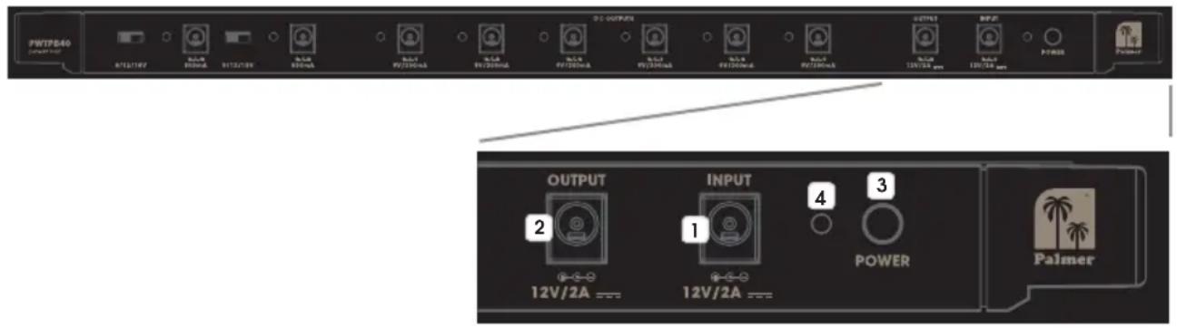
1 INPUT
Low-voltage connector for supplying power to the power supply unit (12 V DC / 2 A, outside: positive). Please use only the provided power adapter, to protect the power supply unit from damage and to ensure sufficient and safe power supply for all connected effects devices.
2 OUTPUT
Low-voltage connector for forwarding the power supply connected to the INPUT socket.
3 POWER
Device ON/OFF button.
4 POWER LED
The POWER LED lights up as soon as the device is correctly connected to the power supply and switched on.

5 DC OUTPUTS
Six low-voltage connectors, each with a 9 V DC and maximum 300 mA current for connecting effects devices with the corresponding load values (9 V DC / outside: positive / up to 300 mA).
6 DISPLAY LEDS
Located next to the sockets, two-tone LEDs for displaying the status of the corresponding DC output. The LEDs light up green to signal correct functioning and turn red in the event of a malfunction (short circuit). In the event of a DC output malfunction, remove the connected low-voltage cable and corresponding effects device, and check both for short circuiting. Once the source of the malfunction has been removed, the DC output is ready for operation again. Unaffected DC outputs remain operational even during a malfunction at one of the other DC outputs.
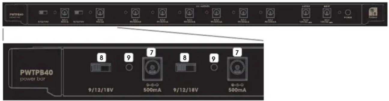
7 DC OUTPUTS
Two low-voltage connectors with a separately switchable output voltage and maximum 500 mA current for connecting effects devices with the corresponding load values (9 V / 12 V / 18 V DC / outside: positive / up to 500 mA).
8 SWITCH 9 / 12 / 18 V
3-way switch for switching the output voltage for low-voltage socket no. 7. Move the switch to the desired position: 9 V left, 12 V middle or 18 V right. Ensure that the output voltage corresponds to the connection value of the relevant effects device, and switch the device on only after having adjusted the output voltage accordingly.
9 DISPLAY LEDS
Located next to the sockets, two-tone LEDs for displaying the status of the corresponding DC output. The LEDs light up green to signal correct functioning and turn red in the event of a malfunction (short circuit). In the event of a DC output malfunction, remove the connected low-voltage cable and corresponding effects device, and check both for short circuiting. Once the source of the malfunction has been removed, the DC output is ready for operation again. Unaffected DC outputs remain operational even during a malfunction at one of the other DC outputs.
INSTALLATION
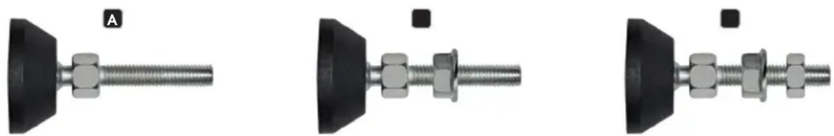
Installation on a pedalboard is possible anywhere where a cross bar is present. Remove the cross bar where the power supply unit is to be installed, and install the unit there. When installing on the upper edge of the pedalboard, use an appropriate tool to remove both adjustable articulated feet with M8 threads, and take out the cross bar attached to the frame. Place one of the supplied M8 nuts in each of the appropriate recesses on the shorter side of the power supply unit, and simultaneously guide both sides (with the Velcro tape on the upper side) into the frame's U-shaped profile. In order to be able to attach the L-shaped metal strip to the adjustable articulated feet, unscrew the M8 nuts on the articulated feet (A), screw on a supplied M8 flange nut with the flange facing the open end (B) and then screw on the previously removed M8 nut (C).
natural_image
Three mechanical assembly diagrams showing a bolted joint with threaded connectors, labeled A, and no visible text or symbols.Use the articulated feet to screw the power supply unit to the frame, locking it into place with the standard M8 nut (D). Now place the L-shaped guard strip on the standard M8 nuts (E) and secure it with the M8 flange nuts (F). For technical reasons, the guard strip may only be positioned on the upper side of the pedalboard.
Positioning the power supply unit elsewhere first requires removal of the cross bar on the upper or lower edge in order to be able to remove the desired cross bar. Once this has been removed from the frame, place one of the supplied M6 nuts in each of the appropriate recesses on the shorter side of the power supply unit and simultaneously guide both sides (with the Velcro tape on the upper side) into the frame's U-shaped profile. Now screw the power supply unit in with the previously removed M6 socket screw.

natural_image
Close-up of a black electronic device with a knob and indicator lights, labeled 'D.F' (no readable text or symbols beyond label)
natural_image
Close-up of a black mechanical component with a knob and mounting bracket (no visible text or symbols)
natural_image
Close-up of a black mechanical component with a knob and mounting bracket (no visible text or symbols)TECHNICAL DATA
Product number: PWTPB40
| Product type: Low-voltage power distributor | |
| Type: Power distributor for Palmer PEDALBAY 40 | |
| Total outputs: 8 (6x 9 V DC, 2x switchable 9/12/18 V DC) + 1x for forwarding input voltage | |
| Output connections: 2.1 x 5.5 mm low-voltage sockets | |
| Output voltage: 9 V DC or 9/12/18 V DC, outside: positive | |
| Output current: Maximum 2 A | |
| Total inputs: 1 | |
| Input connections: 2.1 x 5.5 mm low-voltage socket | |
| Controls: | On/Off switch, 2x voltage switches 9/12/18 V |
| Display elements: | Power LED, 8x status two-tone LEDs(normal operation = green, error = red) |
| Power supply: | External power supply, primary voltage 100–240 V AC/50–60 Hz |
| Operating voltage: | 12 V DC, 2 A, outside: positive |
| Protective circuitry: | Short circuiting and overloading for each output |
| Ambient temperature (in operation): | 0° to 40°C |
| Relative air humidity: | <80%, non-condensing |
| Housing material: | Aluminum |
| Housing finish: | Powder coated/anodised |
| Housing color: | Black |
| Dimensions (W x H x D): | 450 x 24 x 50 mm |
| Weight: | 0.65 kg |
| Accessories included: | External power supply with 1.5 m cable, 9x DC cables, 60 cm, with coaxial power connectors straight to angled, 5x DC cables, 16 cm, with coaxial power connectors straight to angled, 2x M6 + 2x M8 nuts, 2x M8 flange nuts, Velcro tape, L-shaped guard strip and 4 attachment points for cable ties |
MANUFACTURER'S DECLARATIONS
MANUFACTURER'S WARRANTY & LIMITATIONS OF LIABILITY
You can find our current warranty conditions and limitations of liability at: https://cdn-shop.adamhall.com/media/pdf/MANUFACTURERS-DECLARATIONS_PALMER5bb2340e52a8c.pdf To request warranty service for a product, please contact Adam Hall GmbH, Adam-Hall-Str. 1,
61267 Neu Anspach / Email: Info@adamhall.com / +49 (0)6081 / 9419-0.

CORRECT DISPOSAL OF THIS PRODUCT
(valid in the European Union and other European countries with a differentiated waste collection system)
This symbol on the product, or on its documents indicates that the device may not be treated as household waste. This is to avoid environmental damage or personal injury due to uncontrolled waste disposal. Please dispose of this product separately from other waste and have it recycled to promote sustainable economic activity. Household users should contact either the retailer where they purchased this product, or their local government office, for details on where and how they can recycle this item in an environmentally friendly manner. Business users should contact their supplier and check the terms and conditions of the purchase contract. This product should not be mixed with other commercial waste for disposal.
DEUTSCH
natural_image
Three mechanical assembly diagrams showing a bolted joint with threaded end (no text or symbols visible)natural_image
Close-up of a black mechanical device with a knob and adjustment knob, labeled 'D' (no readable text or symbols)
natural_image
Close-up of a black mechanical component with a metallic knob and mounting bracket (no visible text or symbols)
natural_image
Close-up of a black mechanical component with a knob and mounting bracket (no visible text or symbols)TECHNISCHE DATEN
APPAREILS RELIÉS AU SECTEUR
1 ENTRÉE (INPUT)
natural_image
Three mechanical components with bolts and nuts, shown from different angles (no text or symbols visible)natural_image
Close-up of a black mechanical device with a knob and adjustment lever (no visible text or symbols)
natural_image
Close-up of a black mechanical component with a metallic knob and mounting bracket (no visible text or symbols)
natural_image
Close-up of a black mechanical component with a knob and lever (no visible text or symbols)CARACTÉRISTIQUES TECHNIQUES
Référence : PWTPB40
(Valid in the European Union and other European countries with waste separation)
natural_image
Three mechanical fasteners with bolts and bolts, shown from different angles (no text or symbols visible)natural_image
Close-up of a black mechanical device with a knob and adjustment lever (no visible text or symbols)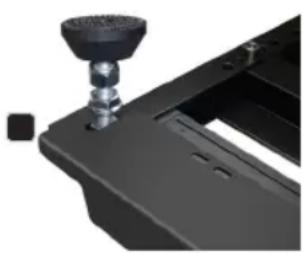
natural_image
Close-up of a black mechanical component with a knob and mounting bracket (no visible text or symbols)
natural_image
Close-up of a black mechanical component with a knob and lever (no visible text or symbols)DATOS TÉCNICOS
natural_image
Three mechanical fasteners with bolts and bolts, shown from different angles (no text or symbols visible)natural_image
Close-up of a black mechanical device with a knob and adjustment knob, labeled 'D' (no readable text or symbols)
natural_image
Close-up of a black mechanical component with a cylindrical knob and mounting base (no visible text or symbols)
natural_image
Close-up of a black mechanical component with a cylindrical knob and mounting bracket (no visible text or symbols)DANE TECHNICZNE
natural_image
Close-up of a mechanical bolt with threaded end and nut (no text or symbols visible)
natural_image
Close-up of a mechanical bolt and nut assembly (no text or symbols visible)
natural_image
Close-up of a mechanical bolt with threaded end and nut, no visible text or symbolsnatural_image
Close-up of a black mechanical device with a knob and adjustment lever (no visible text or symbols)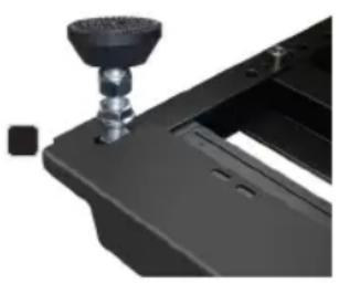
natural_image
Close-up of a black mechanical component with a metallic knob and mounting bracket (no visible text or symbols)