SCplus 40A - Controller IVT - Free user manual and instructions
Find the device manual for free SCplus 40A IVT in PDF.
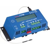
| Product type | Solar controller |
| Brand | IVT |
| Model | SCplus 40A |
| Nominal voltage | 12 V / 24 V (auto-detection) |
| Max. module current | 40 A |
| Max. charging current | 40 A |
| Self-consumption | 25 mA |
| Fuse | 40 A |
| Ambient temperature | -20 °C to +60 °C |
| PC interface | USB type B |
| Temperature sensor | Included (charge voltage adaptation) |
| Automatic system voltage detection | Yes (12/24 V) |
| Deep discharge protection | Adjustable with LED warning |
| Charging profiles | SLA, AGM, GEL, LiFePO4, User |
| Energy meter | Yes (display and software) |
| Configuration software | Free for Windows (download) |
| Power supply | Battery 12/24 V or USB (configuration mode) |
| Maintenance | Check connections, replace fuse with same type |
| Safety | Use in dry environment, do not cover, avoid temperatures >50 °C |
| Spare parts | 40 A fuse, voltage detector adapter |
Frequently Asked Questions - SCplus 40A IVT
User questions about SCplus 40A IVT
0 question about this device. Answer the ones you know or ask your own.
Ask a new question about this device
Download the instructions for your Controller in PDF format for free! Find your manual SCplus 40A - IVT and take your electronic device back in hand. On this page are published all the documents necessary for the use of your device. SCplus 40A by IVT.
USER MANUAL SCplus 40A IVT
Solar Controller SCplus/SCDplus
text_image
SOLAR CONTROLLER i vt STATUS LOAD SCDplus 15 SOLAR + - BATTERY + - LOAD + - BATTERY SENSE TEMPORATIONS 600-700V Cable Cabletext_image
Connection Auto Connect Clear Connection Connecting... Device found on COM4. Auto Disconnect Cleartext_image
Parameters Selected charge profile SLA GEL AGM LiFePO4 User defined Profile parameters 14.2 Stage 1 Voltage 13.8 Stage 2 Voltage 13.2 Stage 3 Voltage 60 Stage 1 Length Inf. Stage 2 Length Load switch settings Load on/off type N/A Load on time 12 : 00 Load off time 12 : 00 Deep disch. settings 10.5 Load off (V) 12.0 Load on (V) 25 Temp. coeff. Date, Time 11:49:44 Time 2014.05.12. Date Sync Energy Counters 0.0 Ah Counter 0.0 kWh Counter Reset System Voltage 12V Default settings Set Read: Parameter read successful. Read Writeline
| Time | Voltage (V) | Charge (A) | |---|---|---| | 14:03 | 8.0 | 0.0 | | 14:05 | 12.0 | 0.0 | | 14:07 | 13.0 | 0.0 | | 14:09 | 14.0 | 0.0 | | 14:11 | 15.0 | 0.0 | Voltage: 12.55V, Charge: 6.0A Load: 0.0A, Temp: N/A Time: 14:14:22 Charge current (A): 15.0 Temperature (Cels): 60.0 Select File SaveKurzerklärung:
Charge current: Ladestrom
Load current: Laststrom
Temperature: Temperatur
C: Ladestrom Stage Length: Dauer der Ladephase
Thank you very much for the trust you have placed in us. You have acquired a reliable high-quality product which will deliver good services for a long time if used appropriately.
Please read these operating instructions thoroughly and completely prior to putting the device into operation. You receive important information for safe operation and maintenance of the device.
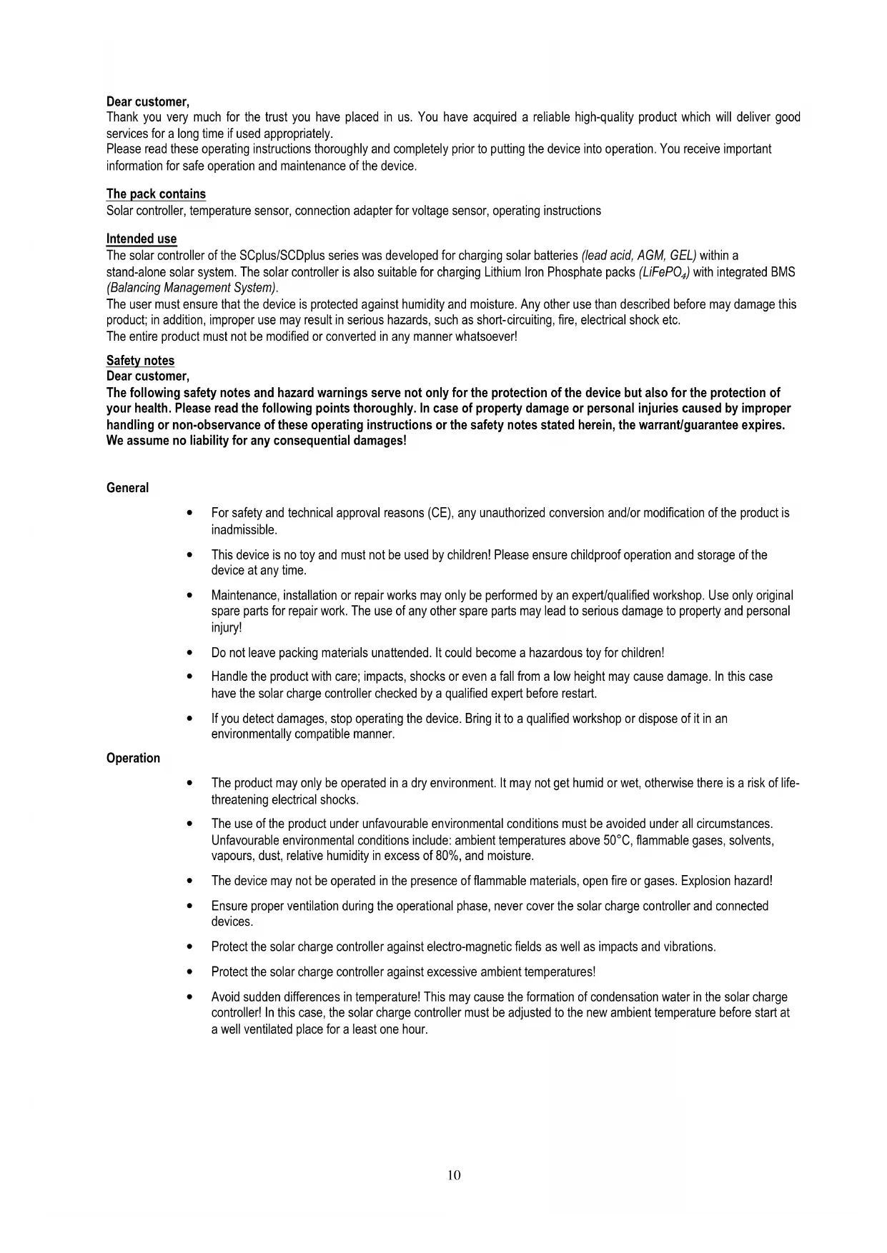
The pack contains
Solar controller, temperature sensor, connection adapter for voltage sensor, operating instructions
Intended use
The solar controller of the SCplus/SCDplus series was developed for charging solar batteries (lead acid, AGM, GEL) within a stand-alone solar system. The solar controller is also suitable for charging Lithium Iron Phosphate packs (LiFePO _4 ) with integrated BMS (Balancing Management System).
The user must ensure that the device is protected against humidity and moisture. Any other use than described before may damage this product; in addition, improper use may result in serious hazards, such as short-circuiting, fire, electrical shock etc.
The entire product must not be modified or converted in any manner whatsoever!
Safety notes
Dear customer,
The following safety notes and hazard warnings serve not only for the protection of the device but also for the protection of your health. Please read the following points thoroughly. In case of property damage or personal injuries caused by improper handling or non-observance of these operating instructions or the safety notes stated herein, the warrant/guarantee expires. We assume no liability for any consequential damages!
General
- For safety and technical approval reasons (CE), any unauthorized conversion and/or modification of the product is inadmissible.
- This device is no toy and must not be used by children! Please ensure childproof operation and storage of the device at any time.
- Maintenance, installation or repair works may only be performed by an expert/qualified workshop. Use only original spare parts for repair work. The use of any other spare parts may lead to serious damage to property and personal injury!
- Do not leave packing materials unattended. It could become a hazardous toy for children!
- Handle the product with care; impacts, shocks or even a fall from a low height may cause damage. In this case have the solar charge controller checked by a qualified expert before restart.
- If you detect damages, stop operating the device. Bring it to a qualified workshop or dispose of it in an environmentally compatible manner.
Operation
- The product may only be operated in a dry environment. It may not get humid or wet, otherwise there is a risk of life-threatening electrical shocks.
- The use of the product under unfavourable environmental conditions must be avoided under all circumstances. Unfavourable environmental conditions include: ambient temperatures above 50°C, flammable gases, solvents, vapours, dust, relative humidity in excess of 80%, and moisture.
- The device may not be operated in the presence of flammable materials, open fire or gases. Explosion hazard!
- Ensure proper ventilation during the operational phase, never cover the solar charge controller and connected devices.
- Protect the solar charge controller against electro-magnetic fields as well as impacts and vibrations.
- Protect the solar charge controller against excessive ambient temperatures!
- Avoid sudden differences in temperature! This may cause the formation of condensation water in the solar charge controller! In this case, the solar charge controller must be adjusted to the new ambient temperature before start at a well ventilated place for a least one hour.
Notes on the battery:
If used improperly, solar batteries are a high risk for humans, animals and the environment.
Always observe the safety instructions of the battery manufacturer!
Solar batteries contain aggressive corrosive acids. Avoid eye and skin contact with liquids from the battery! Never disassemble solar batteries! If eyes or skin get in contact with acid, immediately flood these with running, clear and cool water! Then seek medical help immediately! If acid gets on your clothes, remove the contaminated clothes immediately and flood the affected parts of the skin with running, cool water thoroughly, if required.
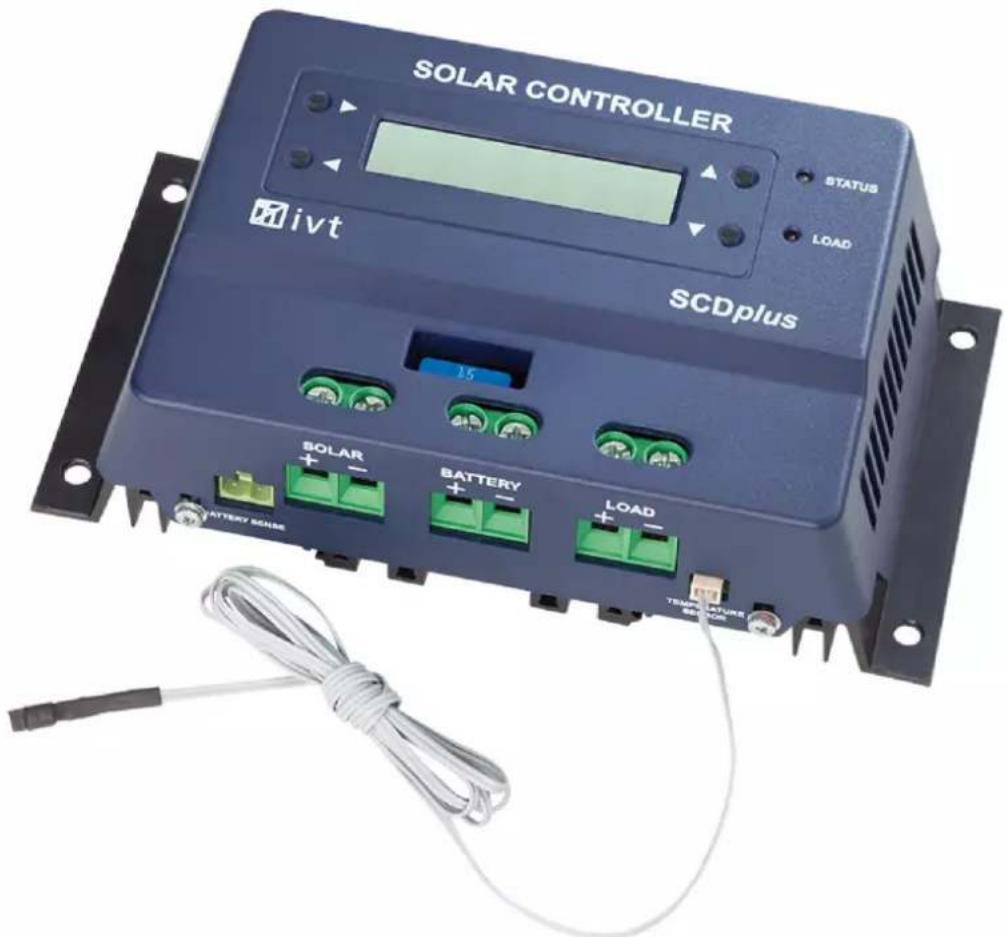
Connections and operating elements
text_image
SOLAR CONTROLLER 3 4 5 6 7 2 STATUS LOAD 8 1 SCDplus SOLAR + - BATTERY + - LOAD 13 12 11 10 9 SOLAR CONTROLLER 14 15 LOAD- Fuse
- Push-button (arrow left) (only SCDplus)
- Push-button (arrow right) (only SCDplus)
- LCD display (only SCDplus)
- Push-button (arrow up) (only SCDplus)
- Push-button (arrow down) (only SCDplus)
- LED "Status"
- LED "Load"
- Connection for temperature sensor
- +/- connection for load output
- +/- connection for solar battery
- +/- connection for solar module
- Connection for voltage sensor
- "Load" push-button for switching the load output on and off
- USB connection for configuration with PC
Features
• Automatic recognition of system voltage (at 12/24 V)
• Temperature-controlled charging
- Adjustable deep discharge protection with early warning
- Module and load cut-off in the positive circuit
• Several charging profiles can be selected (SLA, AGM, GEL, LiFePO4, User)
- Adjustable temperature coefficient
- Switching the load output on and off can be programmed
- Energy meter
• Functions can be adjusted with PC software
• Recording and monitoring by means of PC software
Description of functions
The solar controller works according to the principle of the pulse-width modulated series control, i.e. the downward regulation at the charging limit is achieved by modulating the charging current from the solar module. The temperature sensor adjusts the max. charge voltage automatically to the ambient temperature.
A variety of adjustment options ensures optimum functionality.
SC models can be adjusted on the PC by means of free of charge software.
SCD models may be adjusted by using either the free of charge PC software or the buttons and the display of each device.
The PC software can be downloaded at the following Internet addres: http://www.ivt-hirschau.de/downloads
Assembly
In order to guarantee appropriate operation, please read these operating instructions including safety information completely and carefully before use.
Important note: Please strictly observe the correct sequence when connecting your solar components!
- During assembly ensure that the solar controller and any other system components are mounted in such a way that it is not accessible for children. Danger of life!
-
Do not mount the solar controller directly above a heat source! Ensure that the battery is located in a well ventilated room! Strictly ensure correct polarity!
-
Always ensure proper ventilation of your solar controller. Never cover the ventilation slots of the solar controller. Never use the device in the vicinity of highly flammable materials.
- Remember that large amounts of energy are stored in batteries. In case of short-circuit, these energy quantities can be released in a short time. This means that extreme heat may built up or a fire may break out at the site of short-circuit.
Attention: All components (solar module, battery, consumers and solar controller) must be adjusted to each other concerning voltage and intensity of current. Check this information on the respective type plate. In case of doubt, please contact your dealer. Strictly ensure correct polarity!
Important notes:
- In case of reverse polarity on the load output, devices without own protection may be destroyed. This is why each consumer must be protected individually.
- To ensure safe operation, please strictly pay attention that you observe the correct order, when connecting the individual system components.
Connection sequence:
1. Connecting the battery
Connect the battery at the provided screw type terminals (11) on the solar controller. In order to keep the voltage drop and the related cable heat-up as low as possible, we recommend using an appropriate cable diameter. The terminals are designed for mounting cross-sections up to 16mm^2 .
• The required minimum cross sections are: 1.5 mm ^2 up to 15 A, 4.0 mm ^2 up to 25 A, 10.0 mm ^2 up to 40 A.
• Make sure that the line between battery and solar controller is fused according to instructions.
- Battery and solar controller must be installed in the same room in a small distance.
2. Connecting the solar module
Connect the solar module at the provided screw type terminals (12) on the solar controller.
3. Connecting the load
Finally connect the DC load to the load output (10) of the solar controller.
Perform the configuration according to the symbols on the solar controller or the illustration (see connections and operating elements).
Notes:
- Please observe correct polarity when connecting the DC consumers!
• Make sure that the load output of the solar controller is switched off!
LED display
The LED "Status" (7) informs about the charging status of the battery:
- off charge control in standby mode; no charging of battery
- flashing red
- red battery voltage shortly before lower discharging limit (deep discharge warning) battery voltage at discharge limit; load output is switched off (deep discharge protection)
- green repeatedly 1x short flashing charging in Stage1 mode
- green repeatedly 2x short flashing charging in Stage2 mode
- green repeatedly 3x short flashing charging in Stage3 mode
The LED "Load" (8) informs about the status of the load output:
- Off load output off
- On load output on
For a detailed explanation of the charging modes see the diagram Menu description
Deep discharge protection
Solar batteries must be protected against deep discharging, because it may lead to irreparable damages. The solar charge controller offers reliable protection for the batteries against deep discharging by switching off the connected DC load as soon as the discharge voltage has been reached. As soon as the batteries have sufficiently been recharged over the solar cells, the load output is automatically switched on again depending on the presets.
Overcharge protection
If the max. charge voltage has been reached, the battery is not fully charged yet. Then the load current is reduced so that the max. charge voltage will not be exceeded. This procedure charges the battery in a gentle and fast manner without overcharging it.
Temperature compensation
The temperature probe provides optimum adjustment of the max. charge voltage to the ambient temperature of the battery. For this purpose the controller and battery should be in the same room.
Voltage sensor for battery
Use the supplied connection adapter to connect the "battery sense" connector (13) to the battery terminals to enhance the precision of the function of the solar charge controller.
Changing the fuse
The solar controller is equipped with an easily accessible plug fuse for the charge and load output. Attention: Replace the fuse only by a fuse of the same type and rated current!
LCD display (only in SCDplus models)
As soon as the solar controller is connected with the battery, the initialization phase is running for approx. 10 seconds. The system voltage is identified and taken over by the sensors (Fig. 2). During this phase the following messages appear in the display:
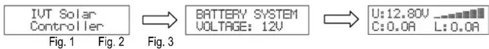
flowchart
graph LR
    A["IVT Solar Controller"] --> B["BATTERY SYSTEM VOLTAGE: 12V"]
    B --> C["U:12.80V\nC:0.0A L:0.0A"]
Attention! Do not push any buttons during this initialization phase!
The display list Fig. 3 displays the following data:
• the current battery voltage (U:)
• the current charging current (C:)
• the current load current (L:)
• the current state of charge (bar graph)
By pressing the ▲ button you switch between the following display messages:
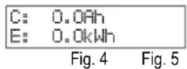
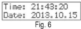
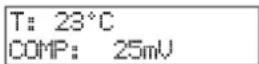
The display lists Fig. 4 - Fig. 6 display the following data:
• the total charge (C:)
• the total energy (E:)
• the current time (Time:)
• the current date (Date:)
• the temperature at the sensor (T:)
• the currently set temperature coefficient (COMP:)

Note:
If the battery cannot be charged due to no or too low solar power, the solar controller switches to standby mode.
Select from the following options to cancel the standby mode:
• automatically by sufficient solar power
- push the 'Load' button (14)
- push the ◀ button (2) (only in SCD models).
Standard device settings (at 12V battery system)
Charging profile/type of rech.battery: SLA (lead-acid battery)
Deep discharge protection: 10.5 V (if the battery falls below a specific charge level, the load output is disconnected automatically)
Temperature coefficient: 25 mV/K
Load output setting: N/A (manual activation of load output using button 14)
Parametrization and monitoring of the solar controller using Windows software
The free of charge software allows all settings to be made conveniently at the PC: date, time, charge profile, deep discharge protection, function of load output and temperature coefficient. You can also monitor and record the operating data of your device. The PC software can be downloaded at the following Internet address. http://www.ivt-hirschau.de/downloads (The download includes the two files: "SC_series_usb.inf" (driver) and "SCControl.msi" (installation data file))
Note:
The solar controller may be parameterized with the PC both with and without battery supply voltage.
When battery voltage is applied, the current operating data will be displayed additionally, which can also be saved on the computer as *.txt file. (see point "Display operating data")
When no battery voltage is applied, the device is powered via the USB cable. ("USB powered mode")
Installation and use of the software:
Installation of application:
- Double-click the setup file "SCControl.msi" to start the installation of the software (This file can also be used to de-install the software)
- Follow the steps of the installation assistant
- After completing the installation process, the file "SCControl.exe" is available on the desktop.
Installation of the device driver:
- Now connect the solar controller to your PC using the USB cable
- Go to "Control Panel" to start the "device manager"
- The solar controller is displayed as "SC/SCD Series Solar Charger"
- Now use the right mouse button to click on the displayed device → "Update driver software"
- Select "Browse my computer for driver software"
- Select the folder which contains the driver file (SC_series_usb.inf) and confirm by clicking "Next"
- Skip appearing safety instructions ( → Install this driver software anyway)
- The driver is installed → The device can now be used
Note:
Using Windows 8 can cause problems with the driver signing. In this case, forcing the signing of the driver must be deactivated. We suggest you learn more about this by referring to Windows 8 Help.
Connecting the device with the PC
- Now connect the solar controller to your PC using the USB cable
- Start the application "SCcontrol.exe"
- Select the tab "Connect to device" in the software window and confirm the "Connect" button.
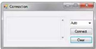
text_image
Connection Auto Connect Clear
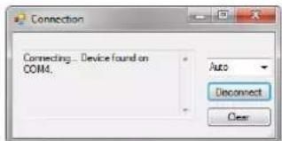
text_image
Connection Connecting... Device found on COM4. Auto Disconnect Clear- The PC automatically recognizes the connected solar controller (the window can then be closed)
- To make the desired device settings, select the tab "Parameters"
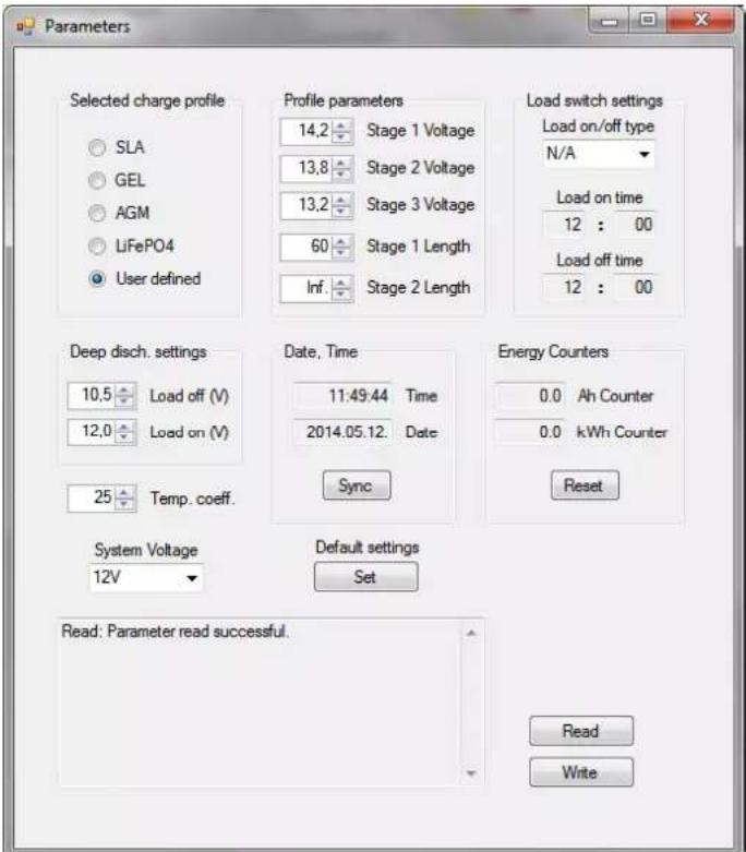
text_image
Parameters Selected charge profile SLA GEL AGM LiFePO4 User defined Profile parameters 14,2 Stage 1 Voltage 13,8 Stage 2 Voltage 13,2 Stage 3 Voltage 60 Stage 1 Length Inf. Stage 2 Length Load switch settings Load on/off type N/A Load on time 12 : 00 Load off time 12 : 00 Deep disch. settings 10,5 Load off (V) 12,0 Load on (V) 25 Temp. coeff. Date, Time 11:49:44 Time 2014.05.12. Date Sync Energy Counters 0.0 Ah Counter 0.0 kWh Counter Reset System Voltage 12V Default settings Set Read: Parameter read successful. Read WriteSetting the charge profile ("Selected charge profile")
You may adjust the charge profile for each type of rechargeable battery here. Select from SLA, GEL, AGM, LiFePO4 and User defined. The appropriate charge profile parameters are displayed in "Profile parameters". If the charge profile "User defined" was selected, the user may also define the settings for the charging level himself.
| Charging profile/ type of rechargeable battery | Charging level 1 voltage | Charging level 1 Duration | Charging level 2 voltage | Charging level 2 Duration | Charging level 3 voltage |
| SLA | 14.0 V | 60 min | 13.7 V | unlimited | - |
| GEL 14.1 V 90 min 13.7 V unlimited - | |||||
| AGM | 14.7 V | 60 min | 13.8 V | unlimited | - |
| LiFePO4 | 14.2 V | 60 min | 13.8 V | unlimited | - |
| USER | User defined | User defined | User defined | User defined | User defined |
Note:
The user-defined charge profile should only be used by experienced users, because the connected rechargeable battery may not be charged completely or damaged if the settings were made in a wrong manner! Uper table is for a 12V battery system. At 24V you have to use the double voltage values. At 48V it must be multiplied with the factor 4.
Load output settings ("Load switch settings")
Four operating modes are available for the load output:
• N/A: Load output switches off permanently when the cutoff voltage has been reached
- AUTO: Load output switches off when the cutoff voltage has been reached and switches on when the reactivation voltage has been reached
- D/N: Load output switches on after 2 minutes without solar power (night light function), switches off when solar power is applied
• TIME: Load output switches off or on at pre-programmed times
If the timer function is selected, any time may be defined for switching the load output on or off. The two input fields "Load on time" and "Load off time" are available for this purpose.
Deep discharge protection setting ("Deep disch. Settings")
By setting the "Load off" value you define the battery voltage at which the load output is switched off to protect the battery against deep discharge. The "Load on" value specifies as of which voltage the load is reconnected, provided the load output mode "Auto" has been selected.
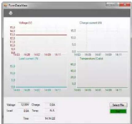
Display operating data ("Data View" mode)
This mode can only be selected if at least the battery voltage is applied to the solar controller.
Any other data will only be displayed if the appropriate components are connected with the solar controller.
The following functions are available for system monitoring:
• Real-time display (diagram) of the current operating data (battery voltage, charge current, load current temperature)
- Storing the operating data in a *.txt file; including time stamp
- Printout of recorded data via your printer
line
| Time | Voltage (V) | Charge current (A) | |---|---|---| | 14:03 | 15.0 | 15.0 | | 14:05 | 14.0 | 10.0 | | 14:07 | 14.0 | 5.0 | | 14:09 | 14.11 | 0.0 | | 14:11 | 14.11 | 60.0 | | 14:13 | 14.11 | 40.0 | | 14:15 | 14.11 | 20.0 | | 14:17 | 14.11 | 0.0 | | 14:19 | 14.11 | 0.0 | Select File Voltage: 12.5kV, Charge: 0.6A Load: 0.6A, Temp: N.A. Time: 14:14:22Brief description:
Voltage: Battery voltage
Charge current: charging current
Load current: Load current
Temperature: Temperature
Time: current time
Select file: Specify storage location
for *.text file
Start/Stop: Start/stop recording
Printer symbol: Print diagrams
In addition, the current date and time can be synchronized, and the energy meter can be reset.
To read the parameters currently defined in the device, select the "Read" button.
If you have made all desired settings, they will be accepted for the device by clicking on the "Write" button. The successful execution of the command is then displayed in the status window.
You may then deactivate the connection with the device ("Disconnect" using the "Connect to device" window).
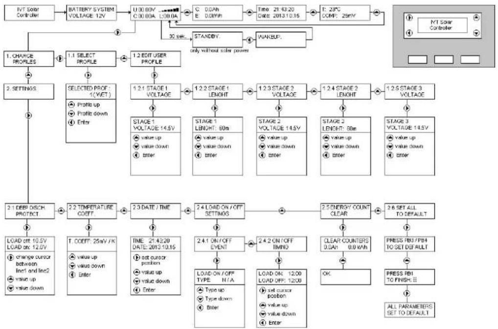
Setting the solar controller on the display (only in SCDplus)
You may use the four buttons on the display to make the following settings: Date, time, charge profile, deep discharge protection, function of load output and temperature coefficient (see the following menu table).
Note: Selected menu items can be undone by using the respective button below.
The values and data in the menus displayed in the diagram only serve as an example and may differ slightly from the current display.
flowchart
graph TD
    A["NT Solar Controller"] --> B["BATTERY SYSTEM VOLTAGE 12V"]
    B --> C["U 0.00kV ...C 0.00kA L 0.00kA"]
    C --> D["C 0.0Ah E 0.0mH"]
    D --> E["Time: 21:43:20 Date: 2013.10.15"]
    E --> F["T: 25°C COMP: 25mV"]
    F --> G["STANDBY..."]
    G --> H["WAKBUF..."]
    H --> I["only without solar power"]

    J["1. CHARGE PROFILES"] --> K["1.1 SELECT PROFILE"]
    K --> L["1.2 EDIT USER PROFILE"]

    M["2. SETTINGS"] --> N["SELECTED PROF: 1(WET)<br>Profile up Profile down Enter"]

    O["2.1 DEEP DISCH PROTECT"] --> P["2.2 TEMPERATURE COEFF"]
    P --> Q["2.3 DATE / TIME"]
    Q --> R["2.4 LOAD ON/OFF SETTINGS"]
    R --> S["2.5 ENERGY COUNT CLEAR"]
    S --> T["2.6 SET ALL TO DEFAULT"]

    U["LOAD OFF: 10.5V<br>LOAD on: 12.5V<br>change cursor between Inc1 and Inc2<br>value up value down"] --> V["T: COEFF: 25mV/K<br>value up value down Enter"]

    W["STAGE 1 VOLTAGE: 14.5V<br>value up value down Enter"] --> X["TAGE 1 LENGTH: 80m<br>value up value down Enter"]

    Y["STAGE 2 VOLTAGE: 14.5V<br>value up value down Enter"] --> Z["STAGE 2 LENGTH: 80m<br>value up value down Enter"]

    AA["STAGE 3 VOLTAGE: 14.5V<br>value up value down Enter"] --> AB["STAGE 3 VOLTAGE: 14.5V<br>value up value down Enter"]

    AC["LOAD ON/OFF TYPE: N/A<br>Type up Type down Enter"] --> AD["LOAD ON: 1200 LOAD OFF: 1200<br>set cursor position<br>value up value down Enter"]

    AE["CLEAR COUNTERS 0.0Ah 0.0 kWh"] --> AF["OK"]

    AG["PRESS PSI/PBA TO SET DEFAULT"] --> AH["PRESS PSI TO FINISH..."]

    AI["ALL PARAMETERS SET TO DEFAULT"] --> AJ["?"]

    AK["NT Solar Controller"] --> AL["?"]
Terms and abbreviations in the menu display
U: Voltage
Stage Voltage:
Voltage during charging
C: Charge current Stage Length: Duration of charging
User-specific charge profile (only for
L: Current at load output
User Profile:
T: Temperature Charge Profile: Charge profile
Time: Time Deep Disch.Protect: Deep discharge protection
Date: Date
Energy Count:
Energy meter
Load: Load output
SLA: Lead-acid battery
AGM:
Lead-acid absorbent glass mat battery
GEL: Lead-gel battery
LiFePO4:
Lithium-iron-phosphate battery
The solar system does not work correctly—possible causes and remedies
Attention! Batteries contain large amounts of energies. In case of short-circuit, these energy quantities can be released in a short time and cause fire at the point of the short circuit due to high heat generation.
| Symptom | Cause | Remedies |
| All LEDs off, display off | Battery is dischargedDefective or loose connection box cableWrong polarity of connection cableFuse defective | Precharge batteryFasten connection cableConnect cable with the correct polarityRectify the cause, replace fuse |
| All LEDs off, display shows "STANDBY" | no sufficient solar powerSolar cable defective | Check solar panelsEliminate interruption or short circuit |
| Display shows 12V system instead of 24V system | 24V battery is deeply discharged during first operation | Precharge battery |
| LED "Status" flashes red | Early deep discharge warning Reduce battery load | |
| LED "Status" lights red | Deep discharge protection activeAwait charging | Reduce battery load |
| Battery is not completely charged | Wrong charge profile selected | Adjust charge profile |
| Battery is overcharging | Wrong charge profile selected | Adjust charge profile |
Technical specifications
| SCplus 15 A | SCplus 25 A | SCplus 40 A | SCDplus 15A | SCDplus | 25A | SCDplus 40 A | SCDplus 40 A/48 V | |
| System voltage | 12/24 V | 12/24 V | 12/24 V | 12/24 V | 12/24 V | 48 V | ||
| Max. solar panel voltage | 50 V | 50 V | 50 V | 50 V | 90 V | |||
| Max. solar panel / load current | 15 A | 25 A | 40 A | 25 A | 40 A | 40 A | ||
| Estimated solar panel power | 180/360 W | 300/600 W | 480/960 W | 180/360 W | 300/600 W | 480/960 W | 1920 W | |
| Cut-off voltage, SLA | 14,0/28,0 V | 56 V | ||||||
| Cut-off voltage, GEL | 14,1/28,2 V | 56,4 V | ||||||
| Cut-off voltage, AGM | 14,7/29,4 V | 58,8 V | ||||||
| Cut-off voltage, LiFePO4 | 14,2/28,4 V | 56,8 V | ||||||
| Trickle charging, SLA/GEL | 13,7/27,4 V | 54,8 V | ||||||
| Trickle charging, AGM/LiFePO4 | 13,8/27,6 V | 55,2 V | ||||||
| Deep discharge protection | 10,5/21,0 V | 42,0 V | ||||||
| Reset voltage | 12,0/24,0 V | 48,0 V | ||||||
| Fuse | 15 A | 25 A | 40 A | 25 A | 40 A | 40 A | ||
| Current consumption, activ | 25 mA | 25 mA | 25 mA | 50 mA | 50 mA | 50 mA | 50 mA | |
| Current consumption, standby | < 10 mA | |||||||
| Operating temperature | -20 °C to +60 °C | |||||||
| Temperatur sensor | ja (extern) | |||||||
| PC interface | USB (Typ B) | |||||||
| Max. efficiency | 98% | |||||||
| Housing | plastic | |||||||
| Dimensions | 19,0 x 10,5 x 5,5 cm | |||||||
| Weight | 0,46 kg | 0,46 kg | 0,48 kg | 0,52 kg | 0,52 kg | 0,54 kg | 0,54 kg | 0,54 kg |
| Part number | 200038 | 200039 | 200040 | 200041 | 200042 | 200043 | 200044 | 200044 |
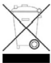
GB - Environmental Protection Notice
At the end of its useful life, this product must not be disposed of together with normal household waste, but has to be dropped off at a collection centre for the recycling of electrical and electronic devices. This is indicated by the symbol on the product, on the instruction manual or on the packaging.
The materials of which this product is made are recyclable pursuant to their labelling. With the reuse, the recycling of the materials or other forms of scrap usage you are making an important contribution to the protection of the environment.
Please ask your local administration office for the appropriate disposal centre.
Technical specifications subject to change. We assume no liability for typographical errors.
text_image
Parameters Selected charge profile SLA GEL AGM LiFePO4 User defined Profile parameters 14.2 Stage 1 Voltage 13.8 Stage 2 Voltage 13.2 Stage 3 Voltage 60 Stage 1 Length Inf. Stage 2 Length Load switch settings Load on/off type N/A Load on time 12 : 00 Load off time 12 : 00 Deep disch. settings 10.5 Load off (V) 12.0 Load on (V) 25 Temp. coeff. Date, Time 11:49:44 Time 2014.05.12. Date Sync Energy Counters 0.0 Ah Counter 0.0 kWh Counter Reset System Voltage 12V Default settings Set Read: Parameter read successful. Read WriteRéglage du profil de chargement („Selected charge profile“)
line
| Time | Voltage (V) | |---|---| | 14.03 | 12.99 | | 14.05 | 0.0A | | 14.07 | 0.0A | | 14.09 | N.A | | 14.11 | 14:14:22 | The chart includes a horizontal line at 12.0 V and a vertical line at 14.09, alongside a line graph showing 'Load current (A)' on the left Y-axis and 'Temperature (Celsius)' on the right Y-axis. The table below is a 'Select File' button.Explications brèves:
Charge current: Courant de recharge
Load current: Courant de charge
text_image
solar Control LEA 14 15text_image
Parameters Selected charge profile SLA GEL AGM LiFePO4 User defined Profile parameters 14.2 Stage 1 Voltage 13.8 Stage 2 Voltage 13.2 Stage 3 Voltage 60 Stage 1 Length Inf. Stage 2 Length Load switch settings Load on/off type N/A Load on time 12 : 00 Load off time 12 : 00 Deep disch. settings 10.5 Load off (V) 12.0 Load on (V) 25 Temp. coeff. Date, Time 11:49:44 Time 2014.05.12. Date Sync Energy Counters 0.0 Ah Counter 0.0 kWh Counter Reset System Voltage 12V Default settings Set Read: Parameter read successful. Read Writeline
| Time | Voltage (V) | Load current (A) | Charge current (A) | |---|---|---|---| | 14.03 | 14.03 | 0.9 | 0.0 | | 14.05 | 14.05 | 10.0 | 0.0 | | 14.07 | 14.07 | 15.0 | 0.0 | | 14.09 | 14.09 | 20.0 | 0.0 | | 14.11 | 14.11 | 25.0 | 0.0 | The chart displays two panels: the left panel is a line graph showing voltage (V) over time with a constant load current (A), and the right panel is a line graph showing charge current (A) over time with a constant temperature (Cels). The data is presented in a table format with 'Voltage' and 'Charge' as the primary variables and 'Temperature' as the secondary variable.Legenda:
Voltage: Accuspanning
Charge current: Laadstroom
Load current: Belastingsstroom