MPPTplus+ 30A - Controller IVT - Free user manual and instructions
Find the device manual for free MPPTplus+ 30A IVT in PDF.
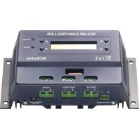
| Product type | MPPT solar charge controller |
| Brand and model | IVT MPPTplus+ 30A |
| System voltage | 12 V / 24 V (automatic detection) |
| Compatible battery types | Open lead, AGM, Gel, LiFePO4 |
| Maximum charge current | 30 A (12 V battery) / 20 A (24 V battery) |
| Maximum module power (12 V) | 360 W |
| Maximum module power (24 V) | 720 W |
| Solar module voltage range | 8 V – 70 V |
| Operating temperature | -20 °C to +60 °C |
| Maximum efficiency | > 97 % |
| Self-consumption (active) | 50 mA |
| Self-consumption (standby) | < 10 mA |
| Dimensions | 187 x 55 x 141 mm |
| Weight | 0.95 kg |
| Fuse | 30 A (replaceable) |
| Display | LCD screen with icons and LED |
| Main functions | MPPT, deep discharge protection, overcharge protection, thermal protection, reverse polarity, adjustable load output, standby |
| Maintenance and cleaning | Clean with a dry cloth; do not use abrasive products |
| Safety | Do not open the housing; use only original spare parts; follow the instructions in the manual |
| Spare parts and repairability | Replaceable fuse; other repairs by a professional |
| General information | User manual included; 2-year warranty |
Frequently Asked Questions - MPPTplus+ 30A IVT
User questions about MPPTplus+ 30A IVT
0 question about this device. Answer the ones you know or ask your own.
Ask a new question about this device
Download the instructions for your Controller in PDF format for free! Find your manual MPPTplus+ 30A - IVT and take your electronic device back in hand. On this page are published all the documents necessary for the use of your device. MPPTplus+ 30A by IVT.
USER MANUAL MPPTplus+ 30A IVT
text_image
Technical diagram of an electronic device rear panel with labeled ports and connectors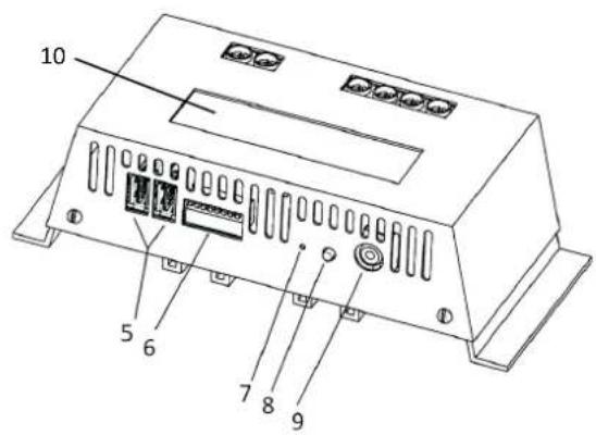
text_image
10 5 6 7 8 9natural_image
Simple line drawing of four battery icons with an arrow pointing to one (no text or symbols)Thank you very much for the trust you have placed in us. You have acquired a reliable high-quality product which will deliver good services for a long time if used appropriately.
Please read these instructions for use thoroughly and completely to familiarize yourself with the product prior to putting it into operation.
This will give you important information for safe operation and maintenance of the device.
Scope of delivery
MPPTplus ^+ solar controller, temperature sensor and operating instructions.
Use in accordance with the intended purpose
The solar controller of the MPPTplus+ series was developed to charge batteries in a solar stand-alone system.
The product is designed for private use only and is not suitable for commercial use. The user must ensure that the device is protected against humidity and moisture. Any use other than the one described above will damage this product. It can also cause hazards, such as short-circuit, fire, electric shocks etc.
The entire product may not be modified or converted, and the housing must not be opened under any circumstances!
Safety notes
Dear customer,
The following safety notes and hazard warnings serve not only for the protection of the device but also for the protection of your health. Please read the following points thoroughly. In case of property damage or personal injuries caused by improper handling or non-observance of these operating instructions or the safety notes stated herein, the warrant/guarantee shall lapse. We assume no liability for any consequential damages!
General
- For safety and technical approval reasons (CE), any unauthorized conversion and/or modification of the product is inadmissible.
- This device is not a toy and must not be used by children! Please ensure childproof operation and storage of the device at all times.
- Maintenance, installation or repair works may only be performed by an expert/qualified workshop. Use only original spare parts for repair work. The use of any other spare parts may lead to serious damage to property and personal injury! The interior of the device does not contain any product components which must be set or maintained by you.
- Do not leave packing material unattended. It could become a hazardous toy for children!
- Handle the product with care; impacts, shocks or even a fall from a low height may cause damage. In this case, have the solar controller checked by a qualified expert before restarting.
- If you detect damage, stop operating the device. Bring it to a qualified workshop or dispose of it in an environmentally compatible manner.
Operation
- The product may only be operated in a dry environment. It may not get damp or wet, otherwise there is a risk of life-threatening electrical shocks.
- The use of the product under unfavourable environmental conditions must be avoided under all circumstances. Unfavourable environmental conditions include: ambient temperatures above 60 °C, flammable gases, solvents, vapours, dust, relative humidity in excess of 80 %, and moisture.
- The device may not be operated in the presence of flammable materials, naked flame or gas. Explosion hazard!
- Ensure proper ventilation during operation, never cover the solar controller and connected devices.
- Protect the solar controller against electromagnetic fields as well as impacts and vibrations.
- Protect the solar controller against heat! Should the solar controller become too hot due to high ambient temperatures, the overheat protection switches the device off to avoid consequential damage. In this case wait until the device has cooled down.
- Avoid sudden differences in temperature! This may cause the formation of condensation in the solar controller! In this case, the solar controller must be adjusted to the new ambient temperature before starting at a well ventilated place for a least one hour.
Notes on the battery
- If used improperly, batteries are a high risk for humans, animals and the environment. Always observe the safety instructions of the battery manufacturer!
- Batteries contain aggressive corrosive acids. Avoid eye and skin contact with liquids from the battery! Never disassemble batteries! If eyes or skin come in contact with acid, immediately rinse with running, clear and cool water! Then seek medical help immediately! If acid gets on your clothes, remove the contaminated clothes immediately and rinse any affected parts of the skin thoroughly with running, cool water.
Features
• MPPT charging control
• Automatic detection of system voltage (12/24 V)
- Input voltage range from 8V-70V
• Suitable for all lead (open, GEL, AGM) and LiFePO _4 batteries
- Standby mode for low own-power consumption
• Temperature-dependent correction of charging parameters
- Deep discharge protection
• Overcharge protection
• Temperature-activated protective circuit
- Reverse polarity protection
- Switchable load output
• Control, monitoring and parametrization via optional additional equipment possible
Description of functions
The MPPTplus ^+ solar controllers are modern, microprocessor-controlled devices which were developed for charging batteries in solar stand-alone systems. The MPPT (maximum power point tracker) enables you to make optimum usage of the solar power of your solar modules. The most efficient operating point of the solar modules changes due to factors such as exposure rate, temperature and the type of solar cells. This optimum operating point (MPP - maximum power point) is monitored constantly by the internal microprocessor of the solar controller and is controlled by the MPPT in such a way that your battery is always charged with maximum power. When the maximum charge voltage of your battery has been reached, the MPPTplus ^+ solar controller switches the charging current off. The microprocessor is also responsible for controlling all important protective functions, such as the deep discharge protection. Its function is to switch off the load output automatically if the battery voltage falls to 10.5 V. As soon as the battery is recharged by the solar module, the load switches back on automatically. The load output can be activated manually using a push-button, and offers the option to switch on and off all consumers connected to the MPPTplus ^+ solar controller by the push of a button.
With the aid of peripheral devices (webbox and touchscreen remote control), you can also control, parameterize and monitor the device and other connected components.
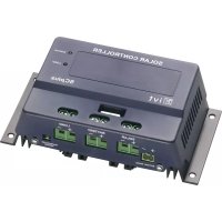
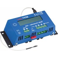
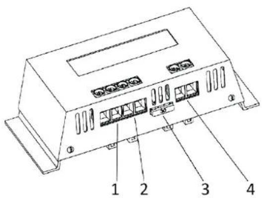
Connection and display elements
text_image
Technical diagram of an electronic device rear panel with labeled ports and connectors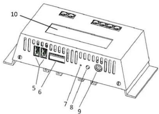
text_image
10 5 6 7 8 9- Connector for solar input (+/-) 5. USB interfaces
- Connector for rechargeable battery input/output (+/-) 6. DIP switch
- Fuse 7. Button for manual battery selection
-
Connector for load output (+/-) 8. Button for consumer on/off
-
Connector for external temperature sensor
-
LCD display
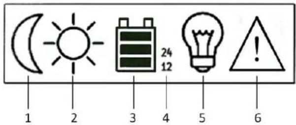
Displays
The MPPTplus ^+ solar controller is equipped with an LCD display for ease of operation and control of the device.
The meaning of each display element is described in the following:
- No solar voltage is applied / device is in standby mode
- Sufficient solar voltage is applied
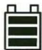
- Battery status indicator (see also battery status indicator)
- Voltage system used
- Status display for load output
- Overvoltage on battery input
text_image
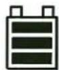
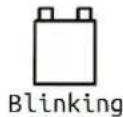
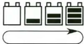
1 2 3 4 5 6 24 12Battery status indicator
Battery being discharged
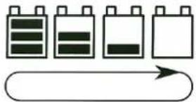
natural_image
Simple line drawing of four battery icons with an arrow below, no text or symbols present.Battery being charged Battery full Battery voltage low

DIP switch assignment
1/2: Addressing of the device
3: MPPT function (switch OFF = function active)
4: Standby function (switch OFF = function active)
5/6: Selection of the type of rechargeable battery
7: Equalizing charge (switch ON = function active)
8: not assigned
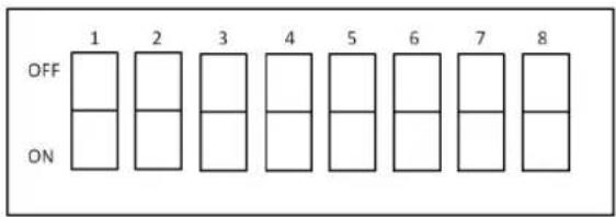
text_image
1 2 3 4 5 6 7 8 OFF ONNote: Only switch when the device is switched off!
Adapting the module power to the solar controller
Strictly ensure that the module power matches the solar controller used!
If you have a module voltage which is significantly higher than the battery voltage, the charging current of the battery will be higher than the given maximum current of the module due to the MPPT function. Example: A module with 36V and 5A charges a 12V battery with max. 15A. This means that an MPPTplus ^4 20 A must be used for this module.
Attention: If you use a solar controller whose charging power is too low, the solar controller may be damaged in the long run!
Maximum module power:
| MPPTplus+ 10 A MPPTplus | + 20 A MPPTplus | + 30 A | ||
| 12 V battery system voltage | 120 W 240 W | 360 W | ||
| 24 V battery system voltage | 240 W 480 W | 720 W | ||
Device addressing
The MPPTplus ^+ series offers the option to control a total of 4 devices simultaneously via a touchscreen remote control (FB-04/FB-05) or a webbox LCD. For this purpose, all the devices used must be connected with each other via the USB interfaces and a unique address must be assigned to the respective device. The addresses are assigned via the DIP switches 1 and 2 on the back of the device.
The following addresses will be assigned:
| DIP switch 1 | DIP switch 2 | Device address |
| OFF | OFF | 1 |
| ON | OFF | 2 |
| OFF | ON | 3 |
| ON | ON | 4 |
Note: A simultaneous use of webbox LCD and FB-04/FB-05 is not possible!
Standby function
If the standby function is activated, the MPPTplus* switches to standby mode after approx. 20s when no or insufficient voltage is applied on the solar input. In this case, the own power consumption is <10 mA.
The power supply of the USB interface is also switched off, so that externally connected devices being supplied with power via the USB connection are no longer functional.
If sufficient solar power is applied, the device switches automatically and immediately from standby mode to operating mode. In this case, the solar voltage must be higher than the battery voltage. The button "Consumer on/off" can be used to reactivate the device manually.
Selecting the type of rechargeable battery and system voltage
The MPPTplus ^+ is suitable for charging lead (open, Gel, AGM) and LiFeP04 batteries.
The respective type of rechargeable battery is selected before the start-up via the DIP switch (5/6) on the back of the device.
| DIP switch 5 DIP switch 6 Type of rechargeable battery | ||
| OFF OFF Lead 12 V | ||
| ON OFF Lead 24 V | ||
| OFF ON AGM battery | ||
| ON ON LiFePO4 | ||
The respective system voltage (12/24 V) is always detected automatically. There is, however, the option of determining the system voltage manually for lead batteries. For this purpose, the required system voltage must be specified via the DIP switches (lead 12 V and lead 24 V). If the "Manual battery selection" button is pressed and held when applying the battery voltage, the reset system voltage is applied, regardless of the actual battery voltage. This can be useful, for example, if 24 V batteries are deeply discharged.
Charging behaviour
The batteries are charged in several stages depending on the set type of rechargeable battery. It can be set via the DIP switch on the back of the device (see point: "Selection of the type of rechargeable battery"). The following table gives information on each charging stage.
| Lead battery 12 V | Lead battery 24 V | AGM battery (12 V / 24 V) | LiFePO4 battery (12 V / 24 V) | |
| Charging stage 1:- Charging end voltage- Duration | 14.1 V5 minutes | 28.2 V5 minutes | 14.7 V / 29.4 V5 minutes | 14.6 V / 29.2 V45 minutes |
| Charging stage 2:- Charging end voltage- Duration | 13.8 Vunlimited | 27.6 Vunlimited | 13.8 V / 27.6 Vunlimited | 14.1 V / 28.2 V90 minutes |
| Charging stage 3:- Charging end voltage- Duration | notavailable | notavailable | notavailable | 13.8 V / 27.6 Vunlimited |
The charging end voltage for lead batteries can be individually defined for the charging stage 1 via remote control or webbox. The temperature is compensated (with connected temperature sensor) both in charging stage 1 and 2. In addition to this, an equalizing charge can be set for this type of rechargeable battery by setting the DIP switch 7 to "ON" before start-up. The duration of charging stage 1 will then be increased to 60 minutes. If the charge profile for LiFePO4 is selected, the setting options for the charging end voltage, equalizing charge and temperature compensation are not available. However, four-cell and also eight-cell LiFePO4 batteries can be used. The detection of the single or double system voltage and the resulting charging behaviour is adjusted automatically.
Equalizing charge
This function sets the duration of charging stage 1 from 5 minutes to 60 minutes. So it is possible to remove sulphate layers in the battery. This function should be used occasionally to extend the life time of the battery.
Assembly
In order to guarantee appropriate operation, please read these operating instructions including safety information completely and carefully before use.
- During assembly, ensure that the solar controller and any other system components are mounted in such a way that they are not accessible to children. Danger to life!
- Do not mount the MPPTplus ^+ solar controller directly above a heat source! Ensure that the battery is located in a well ventilated room! Strictly ensure correct polarity!
- Always ensure proper ventilation of your solar controller. Never cover the ventilation slots of the solar controller. Never use the device in the vicinity of highly flammable materials.
- Remember that large amounts of energy are stored in batteries. In case of short-circuit, these energy quantities can be released in a short time. This means that extreme heat may build up or a fire may break out at the site of short-circuit.
Connecting the solar controller
All components (solar module, battery, consumers and MPPTplus ^4 solar controller) must match each other in terms of voltage and intensity of current. Check this information on the respective type plate. In case of doubt, please contact your dealer.
Strictly ensure correct polarity!
Note: In case of reverse polarity on the load output, devices without own protection may be destroyed. This is why each consumer must be protected individually.
To ensure safe operation, please strictly pay attention that you observe the correct order when connecting the individual system components.
1. Connecting the battery:
Having set the correct type of battery via the DIP switch, connect the battery with the MPPTplus ^4 solar controller by using the screw-type terminals intended for this purpose. Make sure you use a suitable cable cross section to keep the voltage drop and heating of the cables as low as possible. The screw-type terminals are intended for cable cross sections of up to 16mm ^2 .
Required minimum cross sections:
- 1.5mm^2 up to 10 A
- 2.5mm^2 up to 20 A
- 4.0mm^2 up to 30 A
Make sure that the line between battery and MPPTplus ^+ solar controller is fused according to instructions. If the supplied temperature sensor is used, it must be mounted directly on the battery housing to ensure proper function.
2. Connecting the solar module
Connect the solar module with the solar controller using the corresponding screw type terminals.
Note: The maximum off-load voltage of the solar module is 70 V!
3. Connecting the load
Please observe correct polarity when connecting the consumers!
Caution: Make sure that the load output of the solar controller is switched off!
The activated load output is indicated on the display by means of the bulb icon. The load can be switched on and off by pressing the corresponding button.
Attention: It's not allowed to connect the MPPTplus to a PC with the USB interface
Changing the fuse
The solar controllers of the MPPTplus+ series are equipped with a fuse which is accessible from outside and can be replaced easily. Caution: Replace the fuse only by a fuse of the same type and rated current!
Operation with optional additional equipment
Optionally, all models of the MPPTplus+ solar controller series can be controlled, parameterized and monitored with a touchscreen remote control (FB-04, FB-05) or a webbox.
Note: Please consult the manufacturer for more information on the functionality of the respective devices.
Technical specifications
For features and intensity of current, please observe the respective type plate of your device!
| MPPTplus+ 10 | A MPPTplus+ 20 A MPPTplus+ | 30 A | |
| System voltage 12/24 V | |||
| Supported types of rechargeable battery | Lead batteries (open, GEL, AGM), LiFeP04 | ||
| Charging end voltages for lead/AGM/LiFePO4 | 12V system: 14.1V / 14.7 V / 14.6 V 24V system: 28.2V / 29.4V / 29.2 V | ||
| Float voltage 13.8 V / 27.6 V | |||
| Deep discharge protection voltage | 10.5 V / 21.0 V | ||
| Reset voltage 12.5 V / 25.0 V | |||
| Maximum module power 12V system / 24V system | 120 W / 240 W 240 W / 480 W 360 W / 720 W | ||
| Solar module voltage 8 – 70 V | |||
| Max. module/load current 10 A 20 A 30 A / 20 A | |||
| Own consumption, active | 50 mA | ||
| Own consumption, standby | < 10 mA | ||
| Operating temperature | -20°C to +60°C | ||
| Temperature sensor | yes (external) | ||
| Maximum efficiency | >97% | ||
| Fuse | 10 A 20 A | 30 A | |
| Housing | metal | ||
| Dimensions | 187 x 55 x 78 mm | 187 x 55 x 103 mm | 187 x 55 x 141 mm |
| Weight | 0,59 kg | 0,73 kg | 0,95 kg |
Environmental protection note
At the end of its useful life, this product may not be disposed of together with normal household waste, but has to be dropped off at a collection centre for the recycling of electrical and electronic devices. This is indicated by the symbol on the product, on the instruction manual or on the packaging.
The materials of which this product is made are recyclable pursuant to their labelling. With the reuse, the recycling of the materials or other forms of scrap usage, you are making an important contribution to the protection of the environment. Please ask your local authorities for the appropriate disposal centre.
NOTICE D'UTILISATION
text_image
Technical diagram of an electronic device rear panel with labeled ports and components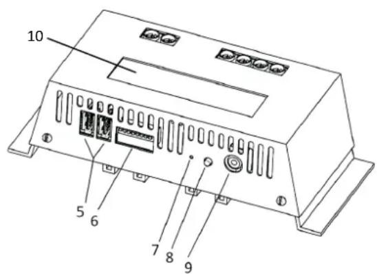
text_image
10 5 6 7 8 9natural_image
Simple line drawing of four battery cells with an arrow pointing to one cell (no text or symbols)natural_image
Simple line drawing of five battery icons with an arrow below, no text or symbols present.Batterie pleine

text_image
Technical diagram of an electronic device rear panel with labeled ports and components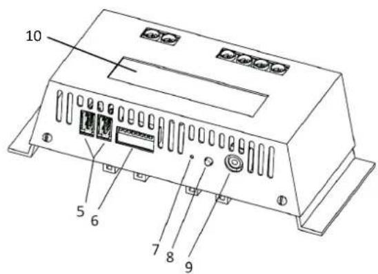
text_image
10 5 6 7 8 9natural_image
Simple line drawing of four battery icons with an arrow below, no text or symbols present.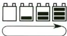
natural_image
Simple line drawing of battery icons with an arrow pointing to one (no text or symbols)