DDX6017 - Car stereo KENWOOD - Free user manual and instructions
Find the device manual for free DDX6017 KENWOOD in PDF.
User questions about DDX6017 KENWOOD
0 question about this device. Answer the ones you know or ask your own.
Ask a new question about this device
Download the instructions for your Car stereo in PDF format for free! Find your manual DDX6017 - KENWOOD and take your electronic device back in hand. On this page are published all the documents necessary for the use of your device. DDX6017 by KENWOOD.
USER MANUAL DDX6017 KENWOOD
MANUEL D'INSTALLATION
MONITOR CON RECEPTOR DVD
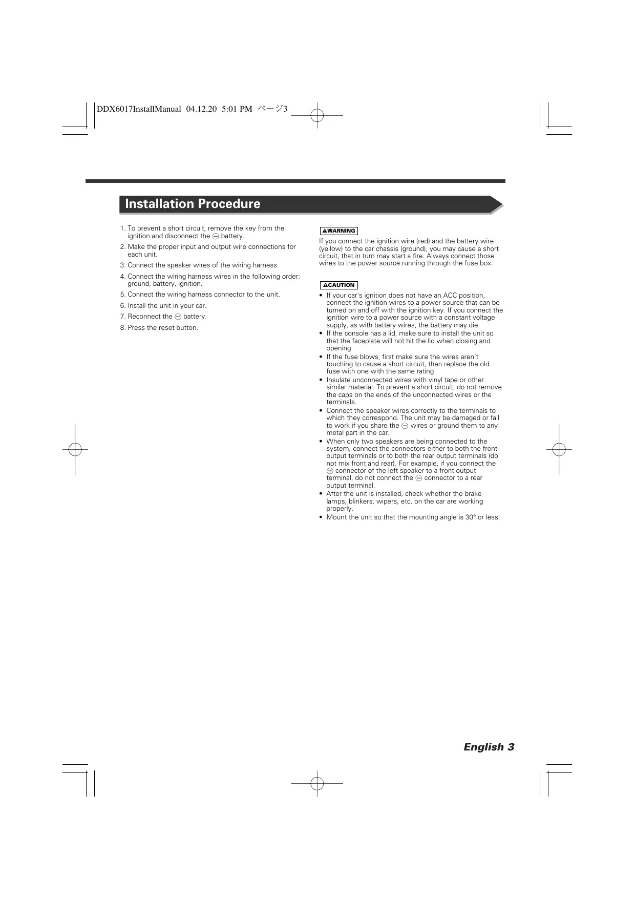
Installation Procedure
- To prevent a short circuit, remove the key from the ignition and disconnect the battery.
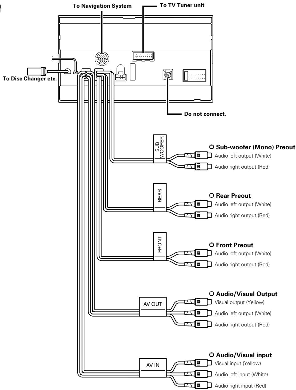
- Make the proper input and output wire connections for each unit.
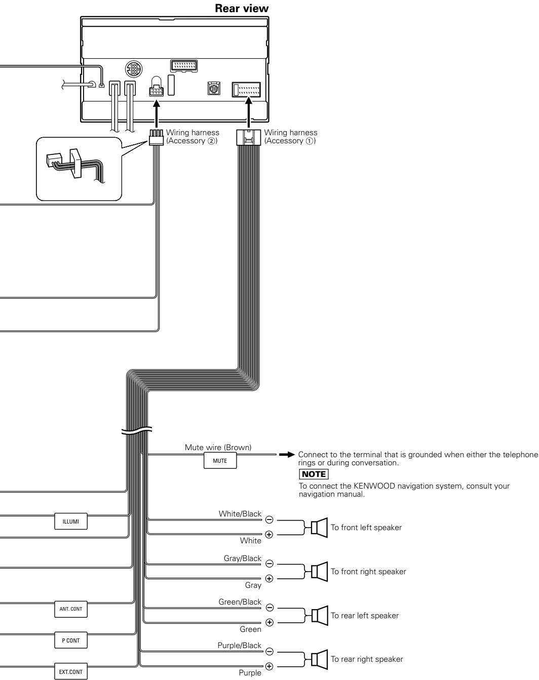
- Connect the speaker wires of the wiring harness.
- Connect the wiring harness wires in the following order: ground, battery, ignition.
- Connect the wiring harness connector to the unit.
- Install the unit in your car.
- Reconnect the battery.
- Press the reset button.
WARNING
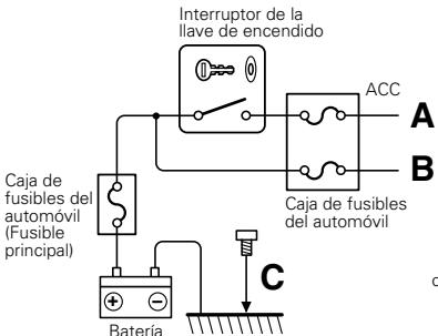
If you connect the ignition wire (red) and the battery wire (yellow) to the car chassis (ground), you may cause a short circuit, that in turn may start a fire. Always connect those wires to the power source running through the fuse box.
CAUTION
- If your car's ignition does not have an ACC position, connect the ignition wires to a power source that can be turned on and off with the ignition key. If you connect the ignition wire to a power source with a constant voltage supply, as with battery wires, the battery may die.
- If the console has a lid, make sure to install the unit so that the faceplate will not hit the lid when closing and opening.
- If the fuse blows, first make sure the wires aren't touching to cause a short circuit, then replace the old fuse with one with the same rating.
- Insulate unconnected wires with vinyl tape or other similar material. To prevent a short circuit, do not remove the caps on the ends of the unconnected wires or the terminals.
- Connect the speaker wires correctly to the terminals to which they correspond. The unit may be damaged or fail to work if you share the wires or ground them to any metal part in the car.
- When only two speakers are being connected to the system, connect the connectors either to both the front output terminals or to both the rear output terminals (do not mix front and rear). For example, if you connect the connector of the left speaker to a front output terminal, do not connect the connector to a rear output terminal.
- After the unit is installed, check whether the brake lamps, blinkers, wipers, etc. on the car are working properly.
- Mount the unit so that the mounting angle is 30^ or less.
WARNING
If you connect the ignition wire (red) and the battery wire (yellow) to the car chassis (ground), you may cause a short circuit, that in turn may start a fire. Always connect those wires to the power source running through the fuse box.
C← Ground wire (Black) (to car chassis)
B Battery wire (5A) (Yellow)
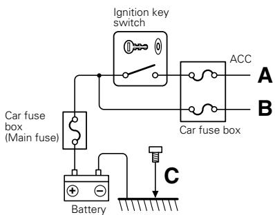
B Battery wire (Yellow)
Dimmer control wire (Orange/White)
A Ignition wire (Red)
C Ground wire (Black) (To car chassis)
Depending on what antenna you are using, connect either to the control terminal of the motor antenna, or to the power terminal for the booster amplifier of the film-type antenna.
When using the optional power amplifier, connect to its power control terminal.
To "EXT.AMP.CONT." terminal of the amplifier having the external amp control function.
Motor antenna control wire (Blue)
Power control wire (Blue/White)
External amplifier control wire (Pink/Black)
System Connection
Installation for Monitor/Player Unit
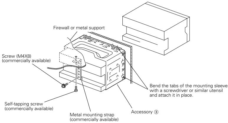

Make sure that the unit is installed securely in place. If the unit is unstable, it may malfunction (eg, the sound may skip).
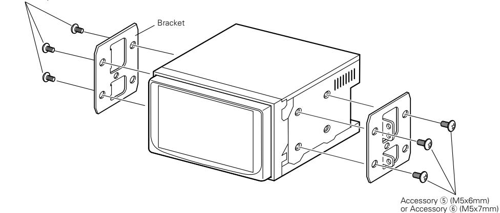
Installing in Japanese-Made Cars
■ Installing on Toyota, Nissan or Mitsubishi Car Using Brackets
Accessory ⑤ (M5x6mm) or Accessory ⑥ (M5x7mm)
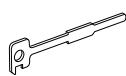
Removing Monitor/Player Unit
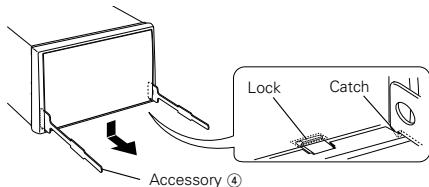
Removing the Hard Rubber Frame (escutcheon)
- Engage the catch pins on the removal tool ④ and remove the two locks on the lower level. Lower the frame and pull it forward as shown in the figure.
- When the lower level is removed, remove the upper two locations.

The frame can be removed from the top side in the same manner.
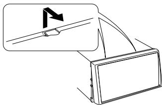
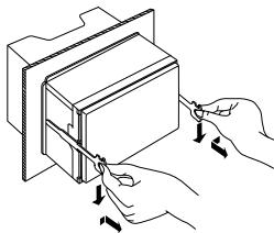
Removing the Unit
- Refer to the section
and then remove the hard rubber frame. - Remove the Hex-head screw with integral washer (M4× 6) on the back panel.
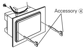
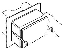
- Insert the two removal tools ④ deeply into the slots on each side, as shown.
- Lower the removal tool toward the bottom, and pull out the unit halfway while pressing towards the inside.

Be careful to avoid injury from the catch pins on the removal tool.
- Pull the unit all the way out with your hands, being careful not to drop it.
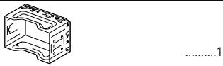
Accessoires
①
②
③
4
2

(5)
(M5 x 6 mm) ......6

6
(M5 x 7 mm) ......6
Cable of la bacteria (5A) (Amarillo)