
PB4SQ - Pump POLARIS - Free user manual and instructions
Find the device manual for free PB4SQ POLARIS in PDF.
| Product Type | Booster pump for pressure pool cleaner |
| Brand | Polaris |
| Model | PB4SQ |
| Number of stages | 4 |
| Motor power | 0.97 HP (725 W) |
| Supply voltage | 230 VAC or 115 VAC, 60 Hz, single-phase |
| Rated current | 4.5 A (230 V) / 9.2 A (115 V) |
| Motor speed | 3450 rpm |
| Dimensions (L × W × H) | 411 mm × 346 mm × 240 mm |
| Inlet/outlet | Barbed quick connect, reinforced hose 6 ft (1.83 m) |
| Plumbing connection | PVC reducer 2" to 3/4" NPT |
| Maximum test pressure | 35 psi (2.4 bar) |
| Required electrical protection | Dedicated ground fault circuit interrupter (GFCI) |
| Grounding | Copper conductor #8 AWG (USA) or #6 AWG (Canada) |
| Minimum distance from pool | 1.5 m (5 ft); in Canada 3 m (10 ft) |
| Installation height | ≤ 30.5 cm (1 ft) above water level |
| Installation type | Fixed, on concrete pad, within 1 m of filter |
| Operation | Non-self-priming, requires flow from filtration pump |
| Compatibility | Polaris pressure pool cleaners |
| Maintenance | Winterize by draining water; do not run dry |
| Warranty | Void if run dry or improperly installed |
| Standards | UL 1081, CSA C22.2 No 108 |
Frequently Asked Questions - PB4SQ POLARIS
User questions about PB4SQ POLARIS
0 question about this device. Answer the ones you know or ask your own.
Ask a new question about this device
Download the instructions for your Pump in PDF format for free! Find your manual PB4SQ - POLARIS and take your electronic device back in hand. On this page are published all the documents necessary for the use of your device. PB4SQ by POLARIS.
USER MANUAL PB4SQ POLARIS
Pressure Cleaner Booster Pump
natural_image
Technical line drawing of a mechanical pump or motor assembly (no text or symbols visible)Installation and Operation Manual
WARNING
FOR YOUR SAFETY - This product must be installed and serviced by a contractor who is licensed and qualified in pool equipment by the jurisdiction in which the product will be installed, where such state or local requirements exist. In the event no such state or local requirement exists, the individual in charge of maintenance must be a professional with sufficient experience in pool equipment installation and maintenance, so that all of the instructions in this manual can be followed exactly. Improper installation and/or operation can create dangerous electrical hazards, which can cause high voltages to run through the electrical system. Before installing this product, read and follow all warning notices and instructions that accompany this product. Failure to follow warning notices and instructions may result in property damage, personal injury, or death. Improper installation and/or operation will void the warranty.
If these instructions are not followed exactly, a fire or explosion may result, causing property damage, personal injury, or death.

ATTENTION INSTALLER: This manual contains important information about the installation, operation and safe use of this product. This information should be given to the owner/operator of this equipment.
Table of Contents
Section 1. IMPORTANT SAFETY INSTRUCTIONS .....3
1.1 Pool Pump Suction Entrapment Prevention Guidelines .....4
Section 2. Overview....5
2.1 Introduction....5
2.2 Description 5
2.3 Dimensions....5
Section 3. Getting Started....6
3.1 Package Contents 6
3.2 Required Equipment....6
3.2.1 Tools 6
3.2.2 Materials Supplied by Installer....6
Section 4. Installation....7
4.1 Plumbing Overview 7
4.2 Location Requirements 8
4.3 Electrical Connections....8
4.3.1 Supply Voltage....8
4.3.2 Bonding and Grounding....9
4.3.3 Electrical Wiring....9
4.3.4 Connect To Controls 10
4.4 Plumbing Connections 11
Section 5. Operation....12
5.1 Pressure Test.... 12
5.2 Start Up 12
5.3 Maintenance....13
5.3.1 Winterizing....13
5.3.2 Troubleshooting and Repair 13
Section 6. Replacement Parts ....15
REGISTER YOUR PRODUCT ONLINE:
www.zodiac.com/en/united-states/contact/product-registration
EQUIPMENT INFORMATION RECORD
DATE OF INSTALLATION
INSTALLER INFORMATION
INITIAL PRESSURE GAUGE READING (WITH CLEAN FILTER)
PUMP MODEL HORSEPOWER
NOTES:
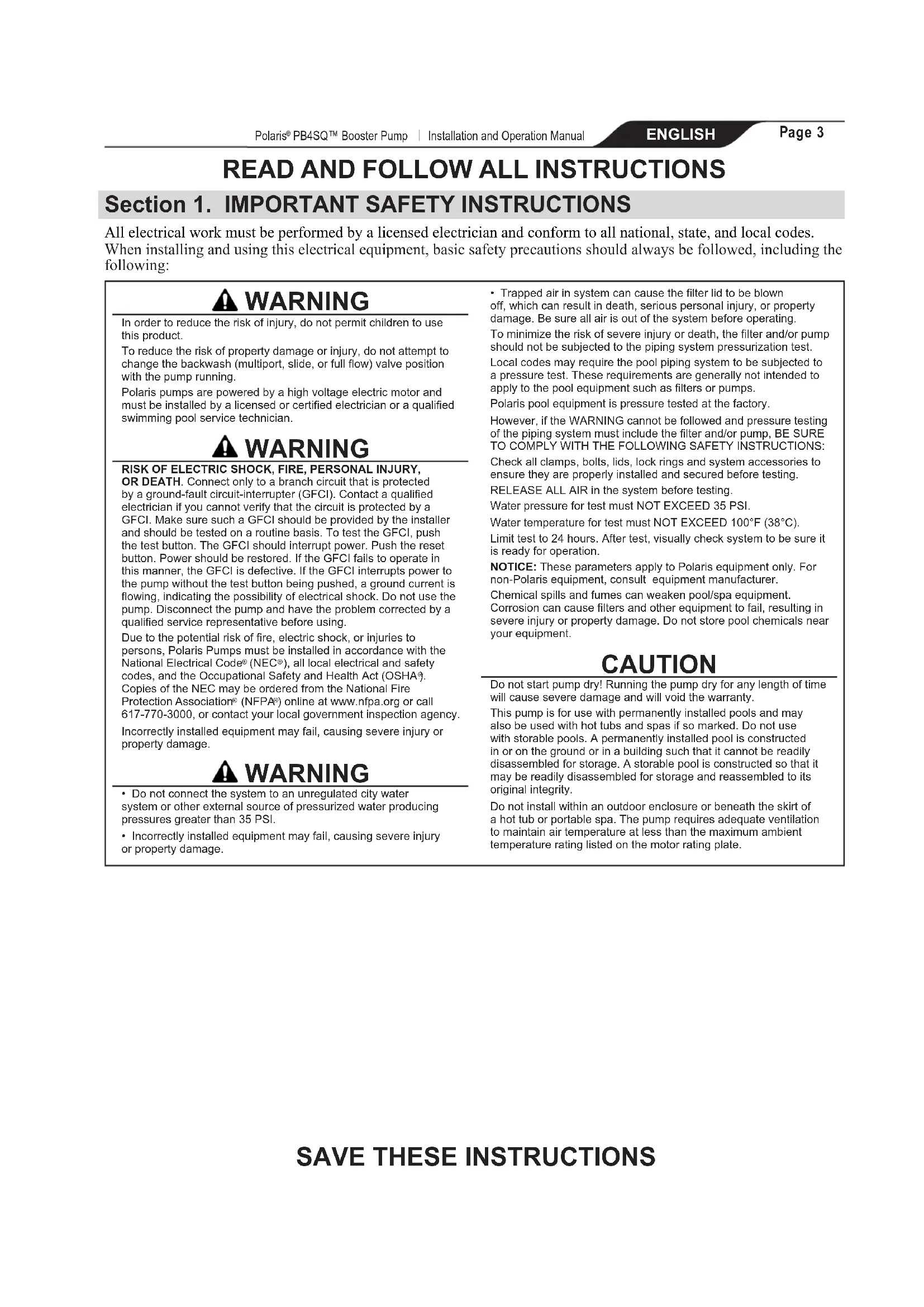
READ AND FOLLOW ALL INSTRUCTIONS
Section 1. IMPORTANT SAFETY INSTRUCTIONS
All electrical work must be performed by a licensed electrician and conform to all national, state, and local codes.
When installing and using this electrical equipment, basic safety precautions should always be followed, including the following:
WARNING
In order to reduce the risk of injury, do not permit children to use this product.
To reduce the risk of property damage or injury, do not attempt to change the backwash (multiport, slide, or full flow) valve position with the pump running.
Polaris pumps are powered by a high voltage electric motor and must be installed by a licensed or certified electrician or a qualified swimming pool service technician.
WARNING
RISK OF ELECTRIC SHOCK, FIRE, PERSONAL INJURY,
OR DEATH. Connect only to a branch circuit that is protected by a ground-fault circuit-interrupter (GFCI). Contact a qualified electrician if you cannot verify that the circuit is protected by a GFCI. Make sure such a GFCI should be provided by the installer and should be tested on a routine basis. To test the GFCI, push the test button. The GFCI should interrupt power. Push the reset button. Power should be restored. If the GFCI fails to operate in this manner, the GFCI is defective. If the GFCI interrupts power to the pump without the test button being pushed, a ground current is flowing, indicating the possibility of electrical shock. Do not use the pump. Disconnect the pump and have the problem corrected by a qualified service representative before using.
Due to the potential risk of fire, electric shock, or injuries to persons, Polaris Pumps must be installed in accordance with the National Electrical Code® (NEC®), all local electrical and safety codes, and the Occupational Safety and Health Act (OSHA®). Copies of the NEC may be ordered from the National Fire Protection Association® (NFPA®) online at www.nfpa.org or call 617-770-3000, or contact your local government inspection agency.
Incorrectly installed equipment may fail, causing severe injury or property damage.
WARNING
- Do not connect the system to an unregulated city water system or other external source of pressurized water producing pressures greater than 35 PSI.
- Incorrectly installed equipment may fail, causing severe injury or property damage.
- Trapped air in system can cause the filter lid to be blown off, which can result in death, serious personal injury, or property damage. Be sure all air is out of the system before operating.
To minimize the risk of severe injury or death, the filter and/or pump should not be subjected to the piping system pressurization test.
Local codes may require the pool piping system to be subjected to a pressure test. These requirements are generally not intended to apply to the pool equipment such as filters or pumps.
Polaris pool equipment is pressure tested at the factory.
However, if the WARNING cannot be followed and pressure testing of the piping system must include the filter and/or pump, BE SURE TO COMPLY WITH THE FOLLOWING SAFETY INSTRUCTIONS:
Check all clamps, bolts, lids, lock rings and system accessories to ensure they are properly installed and secured before testing.
RELEASE ALL AIR in the system before testing.
Water pressure for test must NOT EXCEED 35 PSI.
Water temperature for test must NOT EXCEED 100°F (38°C).
Limit test to 24 hours. After test, visually check system to be sure it is ready for operation.
NOTICE: These parameters apply to Polaris equipment only. For non-Polaris equipment, consult equipment manufacturer.
Chemical spills and fumes can weaken pool/spa equipment.
Corrosion can cause filters and other equipment to fail, resulting in severe injury or property damage. Do not store pool chemicals near your equipment.
CAUTION
Do not start pump dry! Running the pump dry for any length of time will cause severe damage and will void the warranty.
This pump is for use with permanently installed pools and may also be used with hot tubs and spas if so marked. Do not use with storable pools. A permanently installed pool is constructed in or on the ground or in a building such that it cannot be readily disassembled for storage. A storable pool is constructed so that it may be readily disassembled for storage and reassembled to its original integrity.
Do not install within an outdoor enclosure or beneath the skirt of a hot tub or portable spa. The pump requires adequate ventilation to maintain air temperature at less than the maximum ambient temperature rating listed on the motor rating plate.
1.1 Pool Pump Suction Entrapment Prevention Guidelines
WARNING
Pump suction is hazardous and can trap and drown or disembowel bathers. Do not use or operate swimming pools, spa, or hot tubs if a suction outlet cover is missing, broken, or loose. The following guidelines provide information for pump installation that minimizes the risk of injury to users of pools, spas, and hot tubs:
Entrapment Protection - The pump suction system must provide protection against the hazards of suction entrapment.
Suction Outlet Covers - All suction outlets must have correctly installed, screw-fastened covers in place. All suction outlet (drain) covers must be maintained. Drain covers must be listed/certified to the latest version of ANSI®/ASME® A112.19.8 or its successor standard, ANSI/APSP-16. They must be replaced if cracked, broken, or missing.
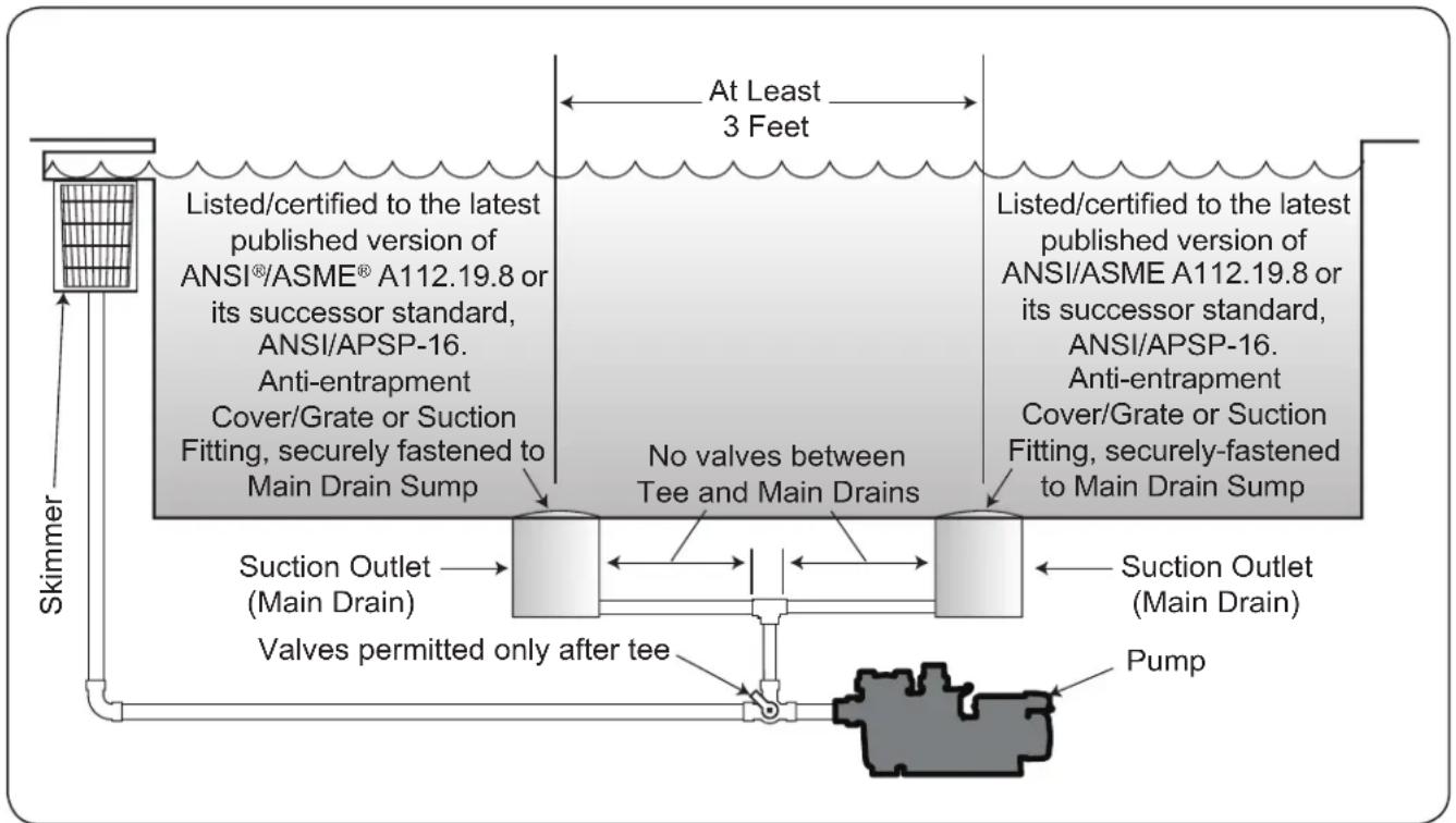
Number of Suction Outlets Per Pump - Provide at least two (2) hydraulically-balanced main drains, with covers, as suction outlets for each circulating pump suction line. The centers of the main drains (suction outlets) on any one (1) suction line must be at least three (3) feet apart, center to center. See Figure 1.
The system must be built to include at least two (2) suction outlets (drains) connected to the pump whenever the pump is running. However, if two (2) main drains run into a single suction line, the single suction line may be equipped with a valve that will shut off both main drains from the pump. The system shall be constructed such that it shall not allow for separate or independent shutoff or isolation of each drain. See Figure 1.
More than one (1) pump can be connected to a single suction line as
long as the requirements above are met.
Water Velocity - The maximum water velocity through the suction fitting or cover for any suction outlet must be 1.5 feet per second unless the outlet complies with the latest version of ANSI/ASME A112.19.8 or its successor standard, ANSI/APSP-16, the standard for Suction Fittings For Use in Swimming Pools, Wading Pools, Spas, and Hot Tubs. In any case, do not exceed the suction fitting's maximum designed flow rate.
If 100% of the pump's flow comes from the main drain system, the maximum water velocity in the pump suction hydraulic system must be six (6) feet per second or less, even if one (1) main drain (suction outlet) is completely blocked. The flow through the remaining main drain(s) must comply with the latest version of ANSI/ASME A112.19.8 or its successor standard, ANSI/APSP-16, the standard for Suction Fittings For Use in Swimming Pools, Wading Pools, Spas, and Hot Tubs.
Testing and Certification - Suction outlet covers must have been tested by a nationally recognized testing laboratory and found to comply with the latest version of ANSI/ASME A112.19.8 or its successor standard, ANSI/APSP-16, the standard for Suction Fittings For Use in Swimming Pools, Wading Pools, Spas, and Hot Tubs.
Fittings - Fittings restrict flow; for best efficiency use fewest possible fittings (but at least two (2) suction outlets).
Avoid fittings which could cause an air trap.
Pool cleaner suction fittings must conform to applicable International Association of Plumbing and Mechanical Officials (IAPMO ® ) standards.
flowchart
graph TD
    A["Skimmer"] --> B["Listed/certified to the latest published version of ANSI®/ASME® A112.19.8 or its successor standard, ANSI/APSP-16. Anti-entrapment Cover/Grate or Suction Fitting, securely fastened to Main Drain Sump"]
    B --> C["Listed/certified to the latest published version of ANSI/ASME A112.19.8 or its successor standard, ANSI/APSP-16. Anti-entrapment Cover/Grate or Suction Fitting, securely fastened to Main Drain Sump"]
    C --> D["Suction Outlet (Main Drain)"]
    D --> E["Valves permitted only after tee"]
    E --> F["Pump"]
    F --> G["At Least 3 Feet"]
    G --> H["No valves between Tee and Main Drains"]
    H --> I["Suction Outlet (Main Drain)"]
    I --> J["Valves permitted only after tee"]
Figure 1. Number of Suction Outlets Per Pump
Section 2. Overview
2.1 INTRODUCTION
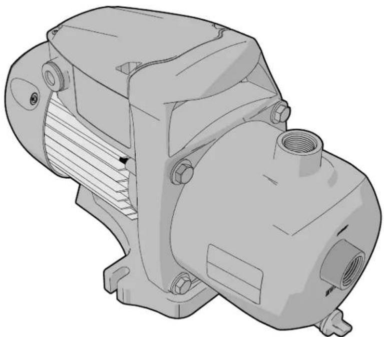
This manual contains information for the proper installation, operation and maintenance of the Polaris PB4SQ booster pump.
CAUTION
Running the booster pump without a filtration pump will damage the booster pump. Improper operation of the booster pump will void the warranty.
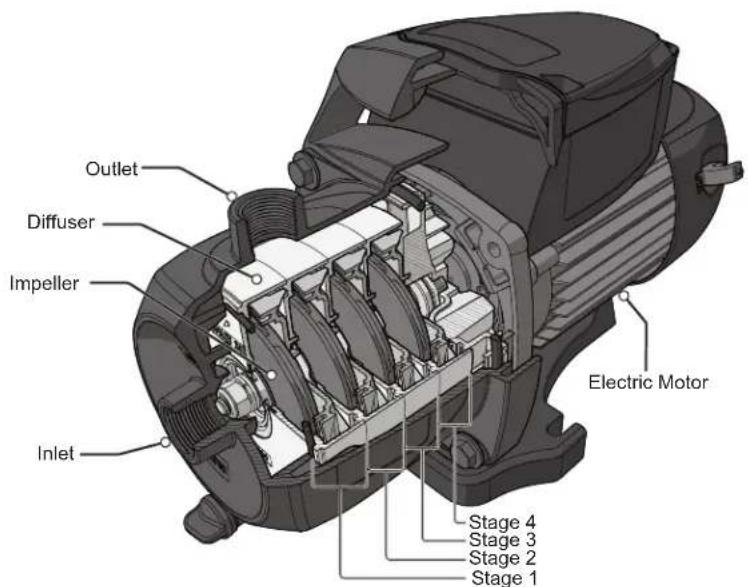
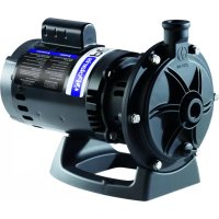
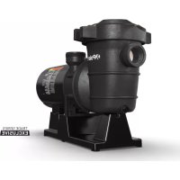
2.2 Description
The Polaris PB4SQ Booster Pump, supplies high pressure water for the operation of pressure driven pool cleaners. The PB4SQ is a multistage booster pump. Hydraulic efficiency is optimized by passing water through four pressurization stages. At each stage, water is moved through an individual impeller and diffuser, progressively increasing outlet pressure without increasing motor Revolutions Per Minute (RPM). This allows a pressure operated cleaner to run with optimal power while minimizing energy consumption. The pump is not self priming and should only be used when the pool filtration pump is on
2.3 Dimensions
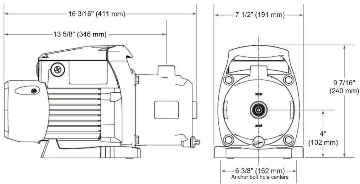
Section 3. Getting Started
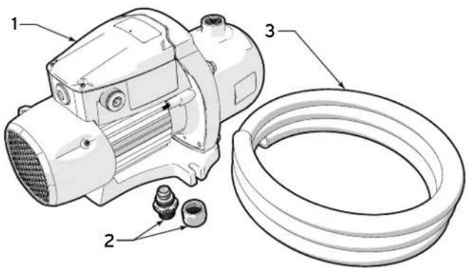
3.1 Package Contents
Before starting, check that you have the correct parts as indicated below. If any parts are missing or incorrect, please call your local distributor or technical support at 1-800-822-7933 for assistance.
| Item | Description Qty. | |
| 1 Polaris PB4SQ Booster Pump 1 | ||
| 2 Polaris Quick Connector Assembly (Barb & Nut) 4 | ||
| 3 Reinforced Hose (6' / 183 cm) 1 | ||
3.2 Required Equipment
Please ensure that the following equipment is available to the installer at the time of installation.
3.2.1 Tools

natural_image
Simple icon of a pair of safety glasses inside a gray circle (no text or symbols)Safety Eyewear Gloves

Phillips Screw-driver
Flat Head
Screwdriver
Hose Cutters

Channel Locks Tape Measure Voltage Meter

Adjustable Wrench

PTFE (Teflon™)
Tape
3.2.2 Materials Supplied by Installer
Please ensure that all materials used during the installation are in accordance with local codes or the authority having jurisdiction (AHJ) requirements. If you have any questions regarding the materials that need to be used during this installation please call technical support at 1-800-822-7933.
NOTE: Required materials may differ from the materials listed. Be sure to confirm with all local and national codes before beginning the installation.
| ELECTRICAL SUPPLIES | PLUMBING SUPPLIES |
| 230 VAC115 VAC | PVC Reducer Bushing (2" - 3/4" NPT) |
| Flexible Conduit | PTFE (TeflonTM) Tape |
Section 4. Installation
4.1 Plumbing Overview
- The pump must be installed on the outlet side of the filter.
- If installed on a dual equipment system with a heater, introduce the booster pump downstream no less than 3' feet (1 m). This ensures that excessively heated water is not passed through the booster pump.
- If using solar heat, ensure that the booster is equipped with an automatic override to shut off the pump. This ensures that the pump will not operate in a no flow condition during solar panel purges.
-
Plumb the booster pump upstream from any chlorination or other sanitation systems.
-
Always use properly sized valves. Jandy Pro Series valves are recommended for best flow capabilities.
- Use the fewest fittings possible.
NOTE: If more than 10 suction fittings are needed, the pipe size must be increased.
- The piping must be well supported and not forced together where constant stress will be experienced.
• A dedicated return line is required.
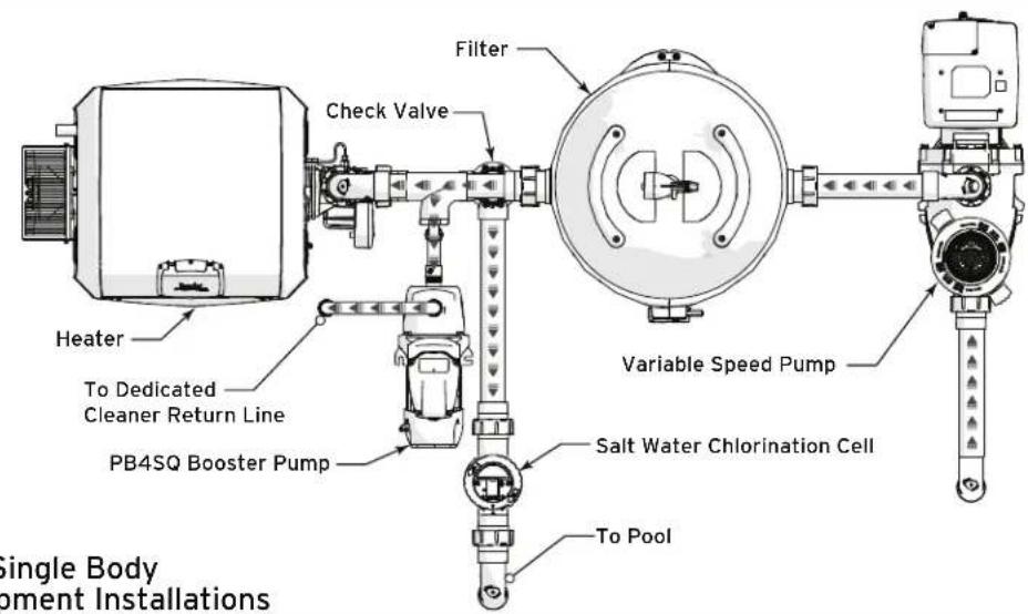
For Single Body Equipment Installations
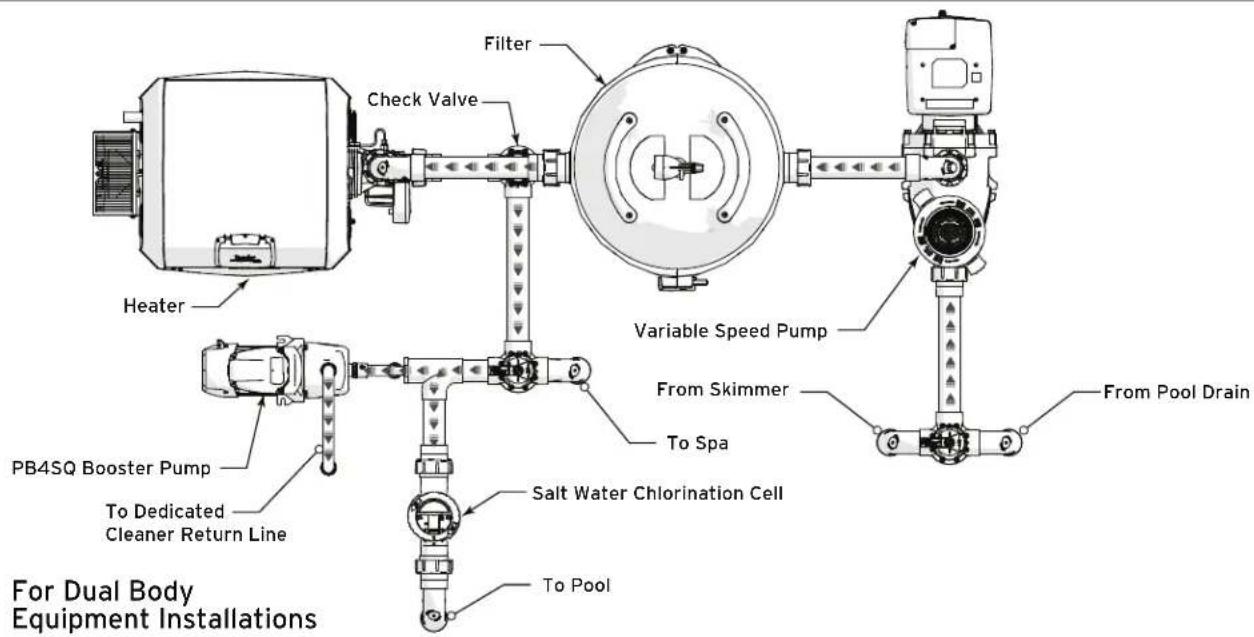
Figure 2. Typical Equipment Layout
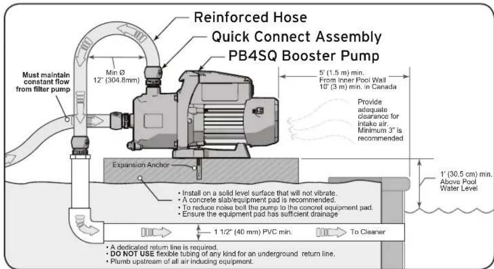
4.2 Location Requirements
- Pump must receive constant flow from the filter pump. The PB4SQ is not a self priming pump. See Figure 2.
- The booster pump inlet connection line should be at least 3/4" pipe.
• To help prevent difficulty in priming, install the inlet line without high points or air locks.
inlet line without high points or air locks.
- The Quick Connect fittings are designed to work with the Polaris reinforced hose (part #P19). See Figure 8
- Return line should be rigid PVC at 1 1/2" (40 mm) Minimum. See Figure 3
- Plumb return line upstream of any air inducing equipment.
• Install the booster pump within 1' (30.5 cm) of the pool water surface. See Figure 3
• The pump should not be elevated more than a few feet above the water level of the pool.
Figure 3. Location Requirements
WARNING
Some Safety Vacuum Release System (SVRS) devices are not compatible with the installation of check valves. If the pool is equipped with an SVRS device, be sure to confirm that it will continue to safely operate when check valves are installed.
NOTE: For installations in Canada the distance from the inner pool edge must be 10' (3 m).
- The pump along with all other circulation equipment must be installed at least 5' (1.5 m) from the inner pool edge. See Figure 3.
- The pump must be placed on a solid foundation that will not vibrate. See Figure 3.
• Install the pump as close to the pool as possible and in a position that will minimize bends in the piping. -
Secure the pump by bolting it to the equipment pad. This will also have the added benefit of helping to reduce vibration noise. See Figure 3.
-
If the pump is installed below the water level, check valves must be installed on both the inlet and return lines to prevent back flow during service or maintenance of the pump.
- The equipment pad must have adequate drainage to prevent water intrusion to the pump.
- The pump needs to be protected from extreme weather exposure.
- Proper ventilation is required in order to avoid excess heat buildup at the pump motor.
- Ensure that sufficient service and maintenance clearances are provided.
- The area around the pump should be clear and free of debris.
- Sufficient space must be left above the pump to allow access to the electrical connections.
- If the equipment is under cover, provide adequate lighting.
- Do Not Install under the skirt or within the outer enclosure of a spa.
4.3 Electrical Connections
4.3.1 Supply Voltage
The pump can be wired for supply voltage of either 230VAC or 115VAC. The pump comes factory wired for 230VAC installation. See section 4.3.3 for details on wiring the motor for 115VAC supply. Correct supply voltage is necessary for proper performance and sustained motor life.
It is the responsibility of the electrical installer to provide proper operating voltage, based on the pump motor rating information found here or on the pump
rating plate, ensuring proper circuit sizes and wire sizes for this specific application.
The National Electrical Code ® (NEC ® , NFPA-70 ® ) requires all pool pump circuits be protected with a
| MOTOR RATING | |
| MODEL | PB4SQ |
| OUTPUT WATTS | 725 |
| HP | 0.97 |
| SERVICE FACTOR | 1.0 |
| RPM | 8450 |
| VOLTS AC | 230/115VAC,1 PHASE,60 HZ |
| AMPS | 4.5/9.2 |
| DUTY | CONT |
Ground Fault Circuit-Interrupter (GFCI). Therefore, it is also the responsibility of the electrical installer to ensure that the pump circuit is in compliance with this and all other applicable requirements of the National Electrical Code ® (NEC ® ) and any other applicable installation codes.
4.3.2 Bonding and Grounding
The motor frame must be grounded to a reliable grounding point using a solid copper conductor, No. 8 AWG (8.4mm 2 ) or larger. In Canada, No. 6 AWG (13.3mm 2 ) or larger must be used. Do not ground to a gas supply line.
The motor must be bonded to all metal parts of the swimming pool, spa, or hot tub structure and to all electrical equipment, metal conduit, and metal piping within five (5) feet (1,5 meter) of the inside walls of the swimming pool, spa, or hot tub. Bond the motor using the provided external lug.
WARNING
To avoid the risk of property damage, severe personal injury, and/or death, always disconnect the power source before working on a motor or its connected load.
CAUTION
Failure to provide data plate voltage (within 10%) during operation will cause the motor to overheat and void the warranty.
WARNING
To avoid the risk of property damage, severe personal injury, and/or death, make sure that the control switch or time clock is installed in an accessible location so that in the event of an equipment failure or a loose plumbing fitting the equipment can be turned off. This location must not be in the same area as the pool pump, filter, and other equipment.
CAUTION
The pump must be permanently connected to a dedicated electrical circuit. No other equipment, lights, appliances or outlets may be connected to the pump circuit, with the exception of devices that may be required to operate simultaneously with the pump, such as a chlorinating device or heater.
4.3.3 Electrical Wiring
MAXIMUM WIRE SIZE AND MAXIMUM OVERCURRENT PROTECTION*
| Distance from Sub-Panel 0-50 feet | (15 meters) 50-100 feet (15-30 meters) 100-200 feet (30-60 meters) | |||||||
| Pump Model | Branch Fuse AMPs Class: CC, G, H, J, K, RK, or T 230 VAC 115 VAC 208-230 VAC | Voltage Voltage Voltage 115 VAC 208-230 VAC 115 VAC | ||||||
| PB4SQ | 15A 15A | 14 AWG (2.1mm2) | 12 AWG (3.3mm2) | 12 AWG (3.3mm2) | 10 AWG (5.3mm2) | 10 AWG (5.3mm2) | 10 AWG (5.3mm2) | |
| *Assumes three (3) copper conductors in a buried conduit and 3% maximum voltage loss in branch circuit. All National Electrical Code® (NEC®) and local codes must be followed. Table shows minimum wire size and branch fuse recommendations for a typical installation per NEC. | ||||||||
-
Turn off all electrical power at the breakers.
-
Ensure that the pump is installed and firmly attached to a solid foundation. See Figure 3.
-
Use flexible conduit to route supply power lines to pump location.
-
Determine the best conduit port to use. There is one on the side and one in the back of the capacitor housing.
-
Loosen do not remove the 4 screws securing the electrical housing cover to the pump body. See Figure 4.
-
Remove the electrical housing cover and seal assembly.
-
Inspect the cover and seal for any damage or improper seating. Replace if necessary.
CAUTION
Be careful not to overtighten any conduit fitting. Overtightening can cause the housing to crack.
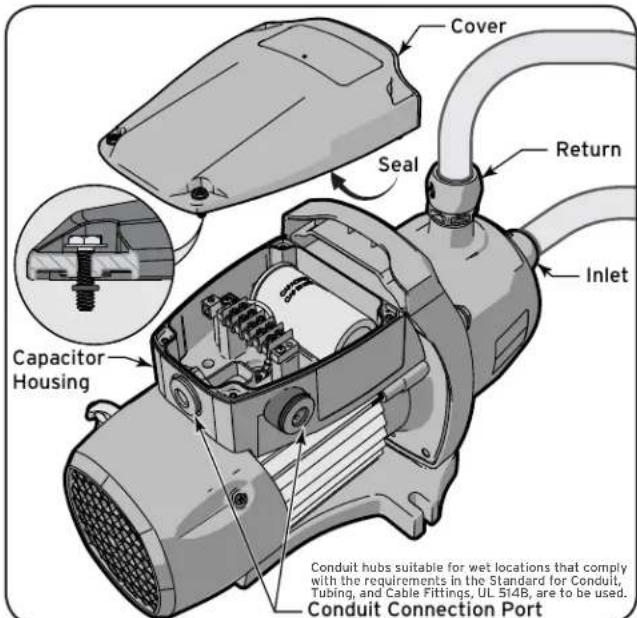
Figure 4. Removing Electrical Access Cover
A. Factory Wiring for 230VAC Supply
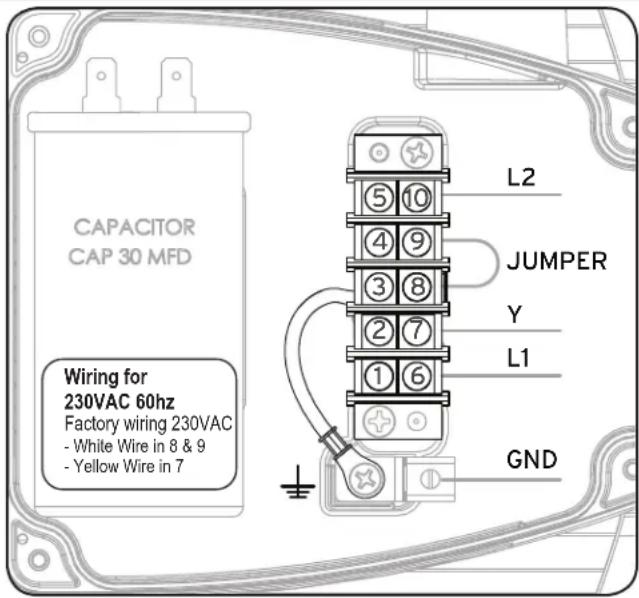
Figure 5. Factory Wiring For 230VAC
The pump is factory wired for 230VAC supply power. For 230VAC installations, do not make any adjustments to the motor's factory wired terminal connections. For use only with flexible wiring systems. Be careful not to damage or abrade any of the wiring during this procedure.
- Remove plug from conduit connection port. See Figure 4.
- Feed supply wires through conduit connection port.
- Wire electrical supply according to Figure 5.
- Secure conduit to the connection port with a 1/2" conduit elbow or comparable conduit connection. See Figure 5. Be careful not to damage or abrade any of the wiring.
- Secure the electrical housing cover using 4 screws. See Figure 4.
4.3.4 Connect To Controls
The pump must be connected to a control so that:
- The filtration pump is operating at all times the booster pump is operating.
- The booster pump is set to run after the filter pump has been running for 30 minutes, and that it shuts off 30 minutes prior to the filter pump turning off.
B. Wiring for 115VAC Supply
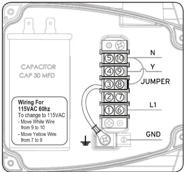
Figure 6. Wiring For 115VAC
The pump is factory wired for 230VAC supply power. Adjustments to the pump wiring are required in order to accommodate this supply voltage. For use only with flexible wiring systems. Be careful not to damage or abrade any of the wiring during this procedure.
- Remove plug from conduit connection port. See Figure 4.
- Feed supply wires through conduit port.
- Rewire factory wiring and wire supply according to Figure 6.
- Secure flexible conduit to conduit connection port with a 1/2" conduit elbow or comparable conduit connection. See Figure 6. Be careful not to damage or abrade any of the wiring.
- Secure the electrical housing cover using 4 screws. See Figure 4.
- When using Jandy automation, wire the booster pump on the Aux 1 relay, and set the DIP switch S1-1 to on. The default label for this preset is "Cleaner" and operating the booster pump on this relay under this DIP switch setting will ensure that the filter pump will work in coordination with the booster pump.
Please review all wiring and programming information in the controls manual to ensure accurate control and coordination between the filter pump and booster pump settings.
4.4 Plumbing Connections
- Disconnect power to the filtration system at the breaker.
- Install a 2" PVC tee downstream from the filter and upstream from any sanitation or chlorination equipment. See Figure 7.
- Connect one leg of the tee to the pool return line.
- On the open leg of the tee install a PVC 2" to 3/4" NPT reducer bushing. Be sure to use approved PVC cement. DO NOT INSTALL with open leg facing up. See Figure 7.
CAUTION
The pump is not self priming and must be filled with water from an upstream filter pump. Never run the booster pump without water. Running the pump "dry" for any length of time can cause severe damage to both the pump and motor and will void the warranty
WARNING
PVC cement and primer can produce vapors that can be hazardous to your health. Use PVC cement to join pipes only in a well ventilated area where vapors cannot accumulate.
Pipe dope should NEVER be used on barb threads. Pipe dope will severely weaken the plastic, causing leakage and may cause the plastic to fracture. DO NOT OVERTIGHTEN
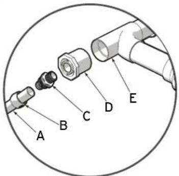
| Callout | Description |
| A | Reinforced Hose |
| B | Quick Connect Nut |
| C | Quick Connect Barbed Fitting |
| D | 2" - 3/4" NPT Reducer Bushing |
| E | 2" PVC Tee |
Figure 7. Plumbing Transition Components
-
Apply 4-6 wraps of PTFE (Teflon™) tape to the tapered threads on all four of the barbed fittings. Be sure to wrap the tape in the opposite direction that the male threads will be turning in order to create a water tight seal. See Figure 9.
-
Install the quick connect barbed fitting into the reducer bushing.
-
Cut the reinforced hose to length. Make sure the cut is square and clean.
-
Slide the quick connect nut over the reinforced hose. See Figure 9.
-
Use water to lubricate the barbs. See Figure 9.
-
Slide the hose over the barbs until a snug fit is achieved. See Figure 8.
-
Tighten the quick connect nuts onto the barbed connector hand tight only. DO NOT OVERTIGHTEN.
- Install a second quick connect barbed fitting at the pump suction inlet. See Figure 9.
- Repeat steps 6-11 to install the reinforced hose at the pump inlet.
- Install the third quick connect barbed fitting at the pump outlet.
- Repeat steps 6-11 to install the reinforced hose at the pump outlet.
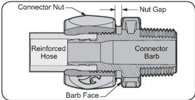
Figure 8. Quick Connect Fitting
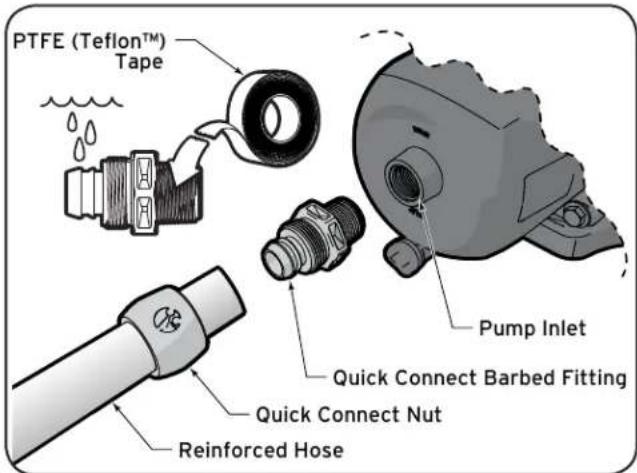
Figure 9. Quick Connect Installation
CAUTION
Be careful not to overtighten any pipe fitting on the inlet or outlet of the booster pump. Overtightening can cause the housing to crack.
- Run the Reinforced hose to the dedicated return line.
- Make sure the dedicated return line has a female 3/4" NPT fitting.
- Install the fourth quick connect barbed fitting at the dedicated return line.
- Repeat steps 6-11 to install the reinforced hose at the dedicated return line.
Section 5. Operation
5.1 Pressure Test
- Fill the system with water, using care to eliminate trapped air.
- Pressurize the system with water to no more than 35 PSI.
- Close the valve to trap pressurized water in the system.
- Observe the system for leaks and/or pressure decay.
- For technical support please call 1-800-822-7933.
WARNING
When pressure testing a system with water, air is often trapped in the system during the filling process. This air will compress when the system is pressurized. Should the system fail, this trapped air can propel debris at a high speed and cause injury. Every effort to remove trapped air must be taken, including opening the bleed valve on the filter and loosening the pump basket lid on the filter pump while filling the pump.
WARNING
Trapped air in system can cause filter lid to be blown off, which can result in death, serious personal injury, or property damage. Be sure all air is properly out of system before operating. DO NOT USE COMPRESSED AIR TO PRESSURE TEST OR CHECK FOR LEAKS.
When pressure testing the system with water, it is very important to make sure that the pump basket lid on the filter pump is completely secure.
Do not pressure test above 35 PSI. Pressure testing must be done by a trained pool professional. Circulation equipment that is not tested properly can fail, which could result in severe injury or property damage.
5.2 Start Up
If this is a new pool installation, make sure all piping is clear of construction debris and has been properly pressure tested. The filter should be checked for proper installation, verifying all connections and clamps are secure according to the manufacturer's recommendations.
WARNING
To avoid risk of damage or injury, verify that all power is turned off before starting this procedure.
- Turn filtration pump ON.
- Open the filter pressure release to relieve the system pressure until water comes out.
- If the filter pump is located below the water level of the pool, opening the filter pressure release valve will prime the pump with water.
- Once all the air has left the filter, close the pressure release valve.
-
Turn on the power to the booster pump.
-
The booster pump should prime. The time it takes to prime will depend on the elevation and length of pipe used on the suction supply pipe.
- If the booster pump does not prime and all the instructions to this point have been followed, check for a suction leak.
CAUTION
Never run the booster pump without water. Running the pump "dry" for any length of time can cause severe damage to both the pump and motor and will void the warranty.
CAUTION
Never run the booster pump without the cleaner connected. Running the pump without the cleaner connected will cause damage to the pump impeller and will void the warranty. Using this pump for any purpose other than running a pressure side pool cleaner will void the warranty
5.3 Maintenance
5.3.1 Winterizing
CAUTION
The pump must be protected when freezing temperatures are expected. Allowing the pump to freeze will cause severe damage and void the warranty.
CAUTION
Do not use antifreeze solutions in the pool, spa, or hot tub systems! Antifreeze is highly toxic and may damage the circulation system. The only exception to this is Propylene Glycol. For more information see your local pool/spa supply store or contact a qualified swimming pool service company.
-
Drain all water from the pump, system equipment, and piping.
-
Remove the drain plug. Store the drain plug in a safe location and reinstall it when the cold weather season is over. Be mindful of the O-ring. Check for damage and wear and replace as needed, please see Section 6 for a complete replacement parts list.
- Keep the motor covered and dry.
NOTE: Covering the pump with plastic will create condensation, and this moisture will damage the pump. The best way to protect your pump is to have a qualified service technician or electrician properly disconnect the electrical wiring at the switch or junction box. Once the power is removed, the two (2) quick connect fittings can be loosened and the pump stored indoors. For safety, and to prevent entry of contaminants, reinstall all conduit and terminal box covers.
- When the system is reopened for operation, make sure all piping, valves, wiring, and equipment are in accordance with the manufacturer's recommendations. Pay close attention to the filter and electrical connections.
- The pump is not self priming and must be filled with water from an upstream filter pump.
5.3.2 Troubleshooting and Repair
Call a licensed and qualified service professional to perform any repairs on the filter/pump system. To locate
a service company, visit www.polarispool.com or contact technical support at 1-800-822-7933.
| Symptom Possible | Problem/Solution |
| Pump won't turn on Ensure that | there is power to the pump using a digital multimeter set on AC voltage. The power supplied to the pump must be within 10% of the nameplate voltageCheck the pump wiring and compare it to the supply voltage. If the pump is wired for 115VAC operation and the supply voltage is 230VAC it will damage the motor.Check the capacitor. If the capacitor is bad replace it and try starting the pump.Check the drive shaft by inserting a 1/4" hex key through the center opening in the fan cover. If the drive shaft does not spin with ease, it may be seized and may need to be replaced. |
| The cleaning/circulating system is not operating correctly. | Verify that skimmer baskets, pump basket and other screens are clean. Clean as necessary.Check filter and clean as necessary.Check valve positions. Adjust as necessary.NOTE Multiple pieces of equipment operating at one time (for example, waterfalls, spa jets, and surface returns) may prevent the cleaning system from working properly.Check the cleaning system manually to ensure that the system is adjusted according to the manufacturer's recommendations. |
| Bubbles present in the filtration pump basket. | Air in system. Check the pool or spa water level to ensure it is at the proper level and that air is not being drawn into the suction piping. If the water is at normal level, turn off the pump. Remove the lid and check for debris around the lid o-ring seat or improper installation of the lid seal (these conditions will cause air to leak into the system). Clean the lid o-ring and replace the lid. Hand-tighten the lid securely until it reaches the "locked" position (follow instructions on lid). Do not use any tools to tighten the lid. Turn the pump back on. |
| Air leaks are still present. Check | the suction side piping union. While the pump is running, try to tighten the union. If this does not stop the air leak, turn off the pump. Loosen both unions and slide the pump out of the way. Remove, clean and re-install both union o-rings on the filtration pump.Reposition the pump next to the piping and secure the union nuts to the pump. With clean union o-rings, hand-tightening of the unions should create a seal. If the unions still do not seal, gently tighten with a large pair of tongue-and-groove pliers.Do not over-tighten using a tool. Doing so will compromise the unions. |
| There is no air in the system, but the pressure is still low. | It is possible that debris is caught in the pump impeller. The pump impeller moves the water, and the vanes in the impeller can become blocked with debris. |
| There is no debris blocking the impeller and the pressure is still low. | The pump impeller is showing signs of normal wear. Have a qualified service technician check the impeller and replace as necessary.Make sure that the first stage O ring is properly installed and is not pinched or damaged.If the pump is part of a relatively new installation, it could be an electrical problem. Contact a qualified service technician. Have the technician check for loose electrical connections and check the voltage at the pump motor while it is in operation. The voltage must be within 10% of the motor's data plate rating. If the voltage is not within 10%, contact a qualified electrician and/or the local power service provider.Pump seal is leaking air. Have a qualified service technician replace the seal. |
| The pump is leaking water between the motor and pump body. | This is caused by a damaged or failed mechanical seal. Replace the seal. |
| The pump gets hot and shuts off periodically. | Ensure that there is adequate room around the motor to circulate air and keep the motor cool. Have a qualified electrician check for loose connections and check the voltage at the pump motor while it is in operation. The voltage must be within 10% of the motor's data plate rating. If the voltage is not within 10%, contact a qualified electrician and/or the local power service provider. |
Section 6. Replacement Parts
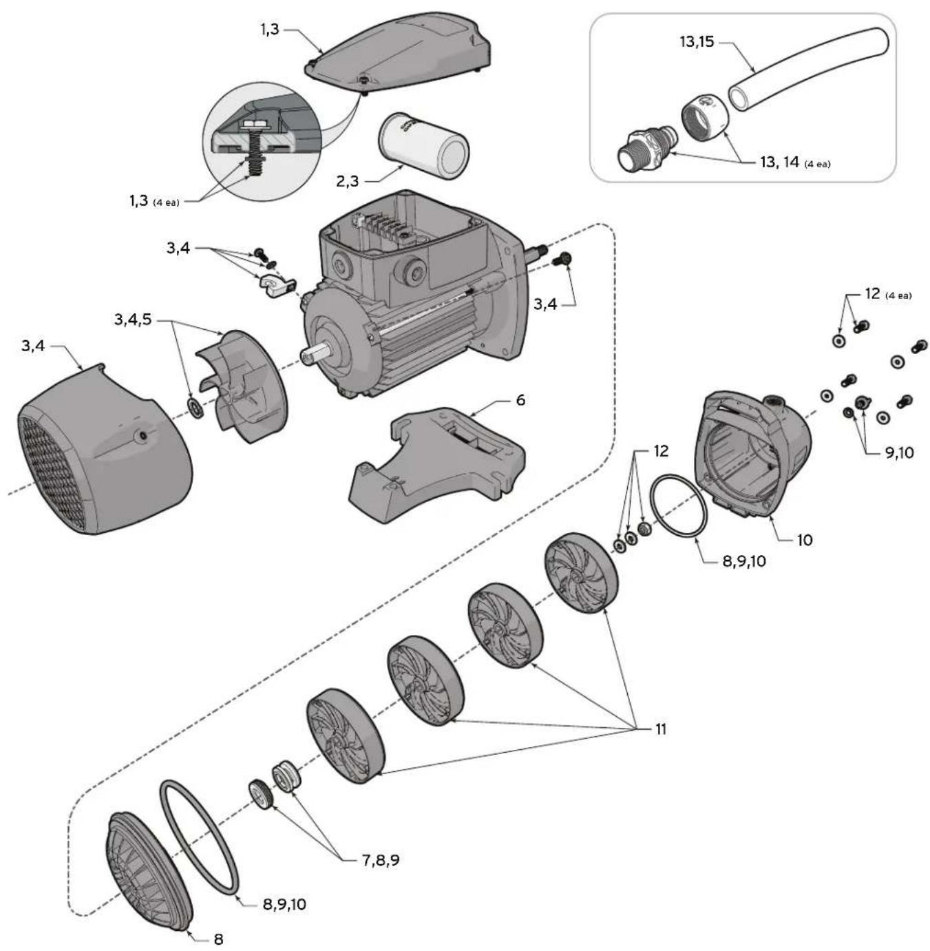
| ITEM | Part # Description |
| 1 | R0722900 Capacitor Housing Cover |
| 2 | R0734500 Capacitor 30MFD 400V |
| 3 | R0734200 Motor Kit |
| 4 | R0722600 Fan Cover |
| 5 | R0723000 Motor Fan |
| 6 | R0722700 Base |
| 7 | R0747800 Mechanical Seal |
| ITEM | Part # Description |
| 8 | R0723200 Backplate Kit |
| 9 | R0734300 Seal Replacement Kit |
| 10 | R0723100 Pump Body |
| 11 | R0722800 Impeller and Diffuser Kit |
| 12 | R0734400 Pump Hardware Kit |
| 13 | R0617100 Quick Connect Install Kit |
| 14 | R0621000 Quick Connect Set |
| 15 | P19 Reinforced Hose 6 ft. |
Zodiac Pool Systems Canada, Inc.
2115 South Service Road West, Unit 3
Oakville, ON L6L 5W2
1.800.822.7933 | www.ZodiacPoolSystems.ca
Zodiac Pool Systems, Inc.
2620 Commerce Way, Vista, CA 92081
1.800.822.7933|www.polarispool.com
ZODIAC® is a registered trademark of Zodiac International, S.A.S.U., used under license.
Polaris® and the Polaris 3-wheeled cleaner design are
registered trademarks of Zodiac Pool Systems, Inc
All trademarks referenced herein are the property of their respective owners.
©2016 Zodiac Pool Systems, Inc. H0544300_REVC

LISTED
CONFORMS TO UL 1081
CERTIFIED TO CSA C22.2 NO 108

Polaris®
PB4SQ™
ENGLISH | FRANÇAIS | ESPAÑOL
natural_image
Technical line drawing of a mechanical pump or motor assembly (no text or symbols visible)Raccordement aux commandes 26
www.zodiac.com/en/united-states/contact/product-registration
FICHE D'INFORMATIONS SUR L'ÉQUIPEMENT
DATE D'INSTALLATION
INFORMATIONS DE L'INSTALLATEUR
LECTURE INITIALE DU MANOMÈTRE (AVEC FILTRE PROPRE)
MODÈLE DE POMPE CHEVAUX-VAPEUR
REMARQUES :
LIRE ET SUIVRE TOUTES LES INSTRUCTIONS
Section 1. CONSIGNES DE SÉCURITÉ IMPORTANTES
Section 4. Installation
4.3.4 Raccordement aux commandes
Zodiac Pool Systems Canada, Inc.
2115 South Service Road West, Unit 3
Oakville, ON L6L 5W2
1.800.822.7933 | www.ZodiacPoolSystems.ca
Zodiac Pool Systems, Inc.
2620 Commerce Way, Vista, CA 92081
1.800.822.7933|www.polarispool.com
natural_image
Technical line drawing of a mechanical pump or motor assembly (no text or symbols visible)www.zodiac.com/en/united-states/contact/product-registration
natural_image
Simple icon of a pair of safety glasses inside a gray circle (no text or symbols)Gafas de seguridad

Guantes
Destornillador Phillips
Zodiac Pool Systems Canada, Inc.
2115 South Service Road West, Unit 3
Oakville, ON L6L 5W2
1.800.822.7933 | www.ZodiacPoolSystems.ca
Zodiac Pool Systems, Inc.
2620 Commerce Way, Vista, CA 92081
1.800.822.7933|www.polarispool.com
- Pressure Cleaner Booster Pump
- Installation and Operation Manual
- WARNING
- Table of Contents
- Section 1. IMPORTANT SAFETY INSTRUCTIONS .....3
- Section 2. Overview....5
- Section 3. Getting Started....6
- Section 4. Installation....7
- Section 5. Operation....12
- Section 6. Replacement Parts ....15
- EQUIPMENT INFORMATION RECORD
- READ AND FOLLOW ALL INSTRUCTIONS
- Section 1. IMPORTANT SAFETY INSTRUCTIONS
- RISK OF ELECTRIC SHOCK, FIRE, PERSONAL INJURY,
- CAUTION
- Pool Pump Suction Entrapment Prevention Guidelines
- Section 2. Overview
- INTRODUCTION
- Description
- Dimensions
- Section 3. Getting Started
- Package Contents
- Required Equipment
- Tools
- Materials Supplied by Installer
- Section 4. Installation
- Plumbing Overview
- Location Requirements
- Electrical Connections
- Supply Voltage
- Bonding and Grounding
- Electrical Wiring
- Connect To Controls
- Plumbing Connections
- Figure 7. Plumbing Transition Components
- Section 5. Operation
- Pressure Test
- Start Up
- Maintenance
- Winterizing
- Troubleshooting and Repair
- Polaris®
- PB4SQ™
- FICHE D'INFORMATIONS SUR L'ÉQUIPEMENT
- LIRE ET SUIVRE TOUTES LES INSTRUCTIONS
- Section 1. CONSIGNES DE SÉCURITÉ IMPORTANTES
- Raccordement aux commandes
Brand : POLARIS
Model : PB4SQ
Category : Pump