V3M3N8200 - Desktop computer ASUS - Free user manual and instructions
Find the device manual for free V3M3N8200 ASUS in PDF.
| Product Type | Desktop Computer (Barebone) |
| Brand | ASUS |
| Model | V3M3N8200 |
| Dimensions (approx.) | 180 x 410 x 380 mm |
| Weight (approx.) | 8 kg |
| Power Supply | 300 W with 115 V/230 V voltage selector |
| Supported CPU Socket | LGA775 (Intel) and Socket 939/AM2 (AMD) |
| Memory Type | DDR DIMM |
| Number of Memory Slots | 4 (depending on motherboard) |
| Storage Bays | 2 x 5.25" bays, 2 x 3.5" internal bays |
| Front Panel Ports | 2 USB 2.0 ports, headphone and microphone ports, HDD LED, Power and Reset buttons |
| Rear Panel Ports | PS/2 keyboard and mouse, VGA, parallel, USB 2.0, LAN RJ-45, E-SATA or COM or DVI or S/PDIF, 6/8-channel audio |
| Main Functions | Installation of CPU, memory, expansion cards, optical drives, hard drives and floppy drives |
| Maintenance and Cleaning | Unplug before cleaning, use a soft dry cloth, do not use abrasive products |
| Safety | Disconnect the power supply before any intervention, avoid touching CPU pins, respect electrical voltages |
| Spare Parts and Repairability | Standard components (CPU, RAM, drives, power supply) easily replaceable |
| General Information | ASUS V Series, manual available in multiple languages, warranty according to reseller |
Frequently Asked Questions - V3M3N8200 ASUS
User questions about V3M3N8200 ASUS
0 question about this device. Answer the ones you know or ask your own.
Ask a new question about this device
Download the instructions for your Desktop computer in PDF format for free! Find your manual V3M3N8200 - ASUS and take your electronic device back in hand. On this page are published all the documents necessary for the use of your device. V3M3N8200 by ASUS.
USER MANUAL V3M3N8200 ASUS
ASUS PC (Desktop Barebone)
Installation manual

natural_image
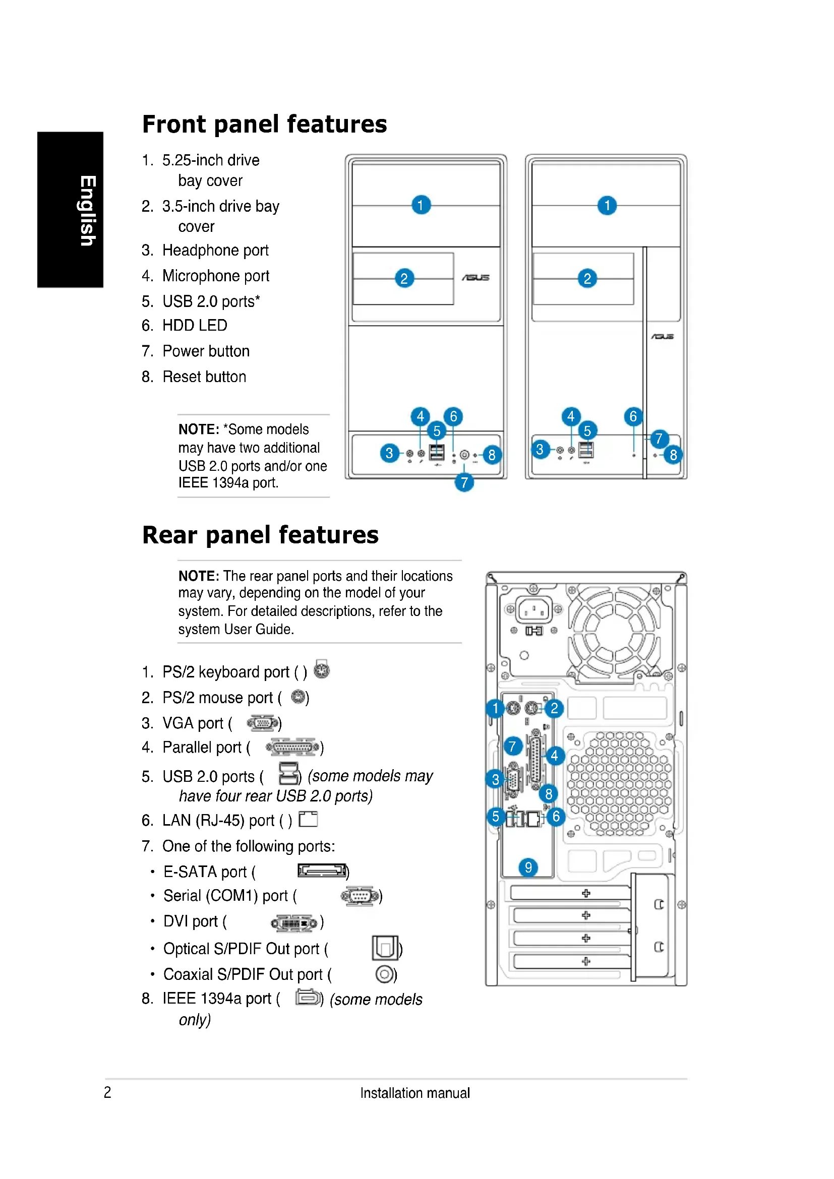
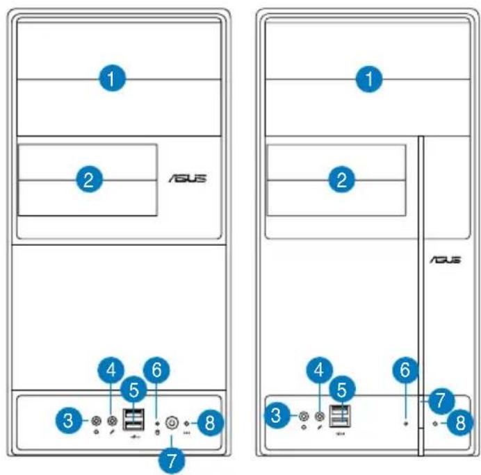
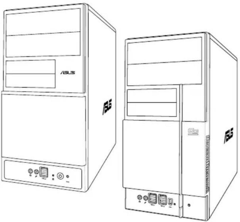
Line drawings of two different desktop computer cabinets, one labeled 'ASUS' and the other 'F5', showing front and side views without any text or symbols on the cabinet bodies.Front panel features
- 5.25-inch drive bay cover
- 3.5-inch drive bay cover
- Headphone port
- Microphone port
- USB 2.0 ports*
- HDD LED
- Power button
- Reset button
NOTE: *Some models may have two additional USB 2.0 ports and/or one IEEE 1394a port.
text_image
1 2 ASUS 4 5 6 3 8 7 1 2 4 5 6 3 7 8 ASUSRear panel features
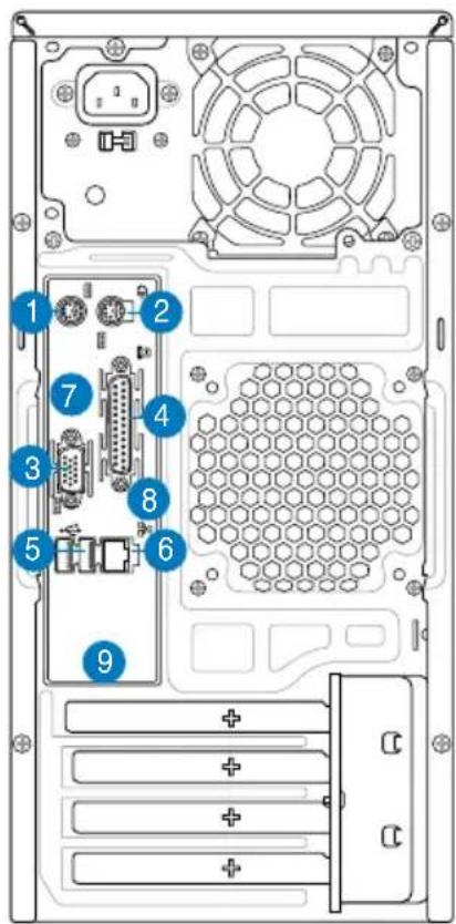
NOTE: The rear panel ports and their locations may vary, depending on the model of your system. For detailed descriptions, refer to the system User Guide.
- PS/2 keyboard port ( )
- PS/2 mouse port ( Ⓞ)
- VGA port ( )
- Parallel port ( )
- USB 2.0 ports ( ) (some models may have four rear USB 2.0 ports)
- LAN (RJ-45) port ()
- One of the following ports:
• E-SATA port (
- Serial (COM1) port (
• DVI port (
• Optical S/PDIF Out port (
- Coaxial S/PDIF Out port (
- IEEE 1394a port ( ) (some models only)
text_image
Diagram of a computer tower rear panel with numbered components and labeled connectors- One of the following audio ports configurations:
- 6-channel
• 8-channel
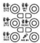
Refer to the configuration table in the User Guide for details.
Internal components
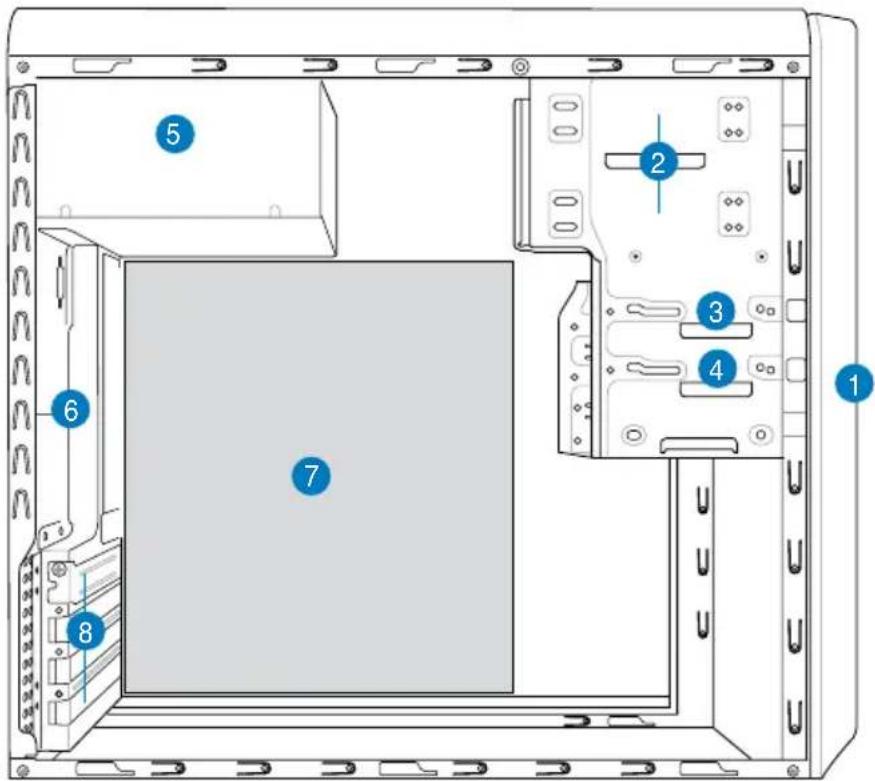
text_image
Diagram of a computer tower case with numbered components for identification- Front panel cover
- 5.25-inch optical drive bays
- Floppy disk drive bay
-
Hard disk drive bay
-
Power supply unit
- Chassis fan slot
- ASUS motherboard*
- Expansion slot metal brackets
NOTE: *Refer to the system User Guide for motherboard details.
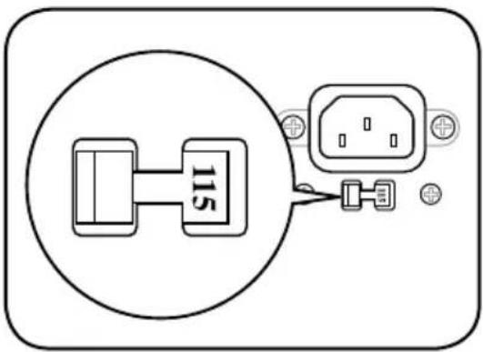
Selecting the voltage
The system's power supply unit has a 115 V/230 V voltage selector switch located beside the power connector. Use this switch to select the appropriate system input voltage according to the voltage supply in your area.
If the voltage supply in your area is 100-127 V, set the switch to 115 V.
If the voltage supply in your area is 200-240 V, set the switch to 230 V.
text_image
115NOTE: Refer to the system User Guide for the exact location of the voltage selector.
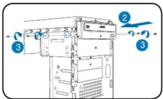
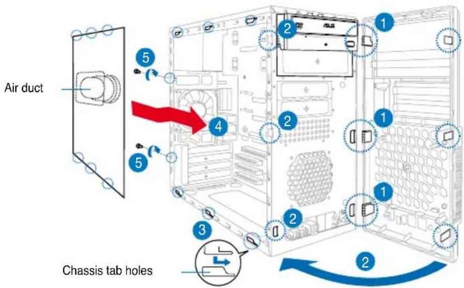
Removing the side cover and front panel assembly
- Remove the cover screws on the rear panel.
- Pull the side cover toward the rear panel until its hooks disengage from the chassis tab holes. Set the side cover aside.
- Locate the front panel assembly hooks, then lift them until they disengage from the chassis.
- Swing the front panel assembly to the right, until the hinge-like tabs on the right side of the assembly are exposed.
- Remove the front panel assembly, then set aside.

text_image
Air duct Chassis tab holesInstalling a CPU
Installing an Intel® Pentium® 4 CPU in the LGA775 package
- Locate the CPU socket on the motherboard.
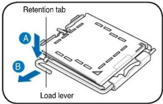
- Press the load lever with your thumb (A), then move it to the left (B) until it is released from the retention tab.
CAUTION. To prevent damage to the socket pins, do not remove the PnP cap unless you are installing a CPU.
text_image
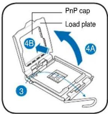
Retention tab A B Load lever- Lift the load lever in the direction of the arrow to a 135^ angle.
- Lift the load plate with your thumb and forefinger to a 100^ angle (4A), then push the PnP cap from the load plate window to remove (4B).
- Position the CPU over the socket, making sure that the gold triangle is on the bottom-left corner of the socket. Fit the socket alignment key into the CPU notch.
- Close the load plate (A), then push the load lever (B) until it snaps into the retention tab.
text_image
PnP cap Load plate 4B 4A 3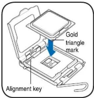
text_image
Gold triangle mark Alignment key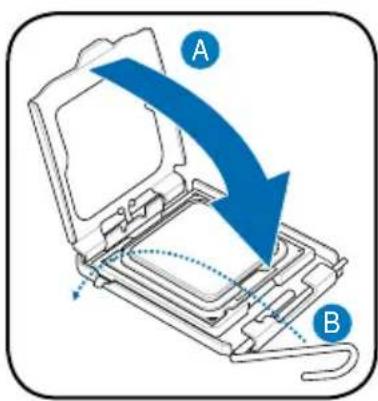
text_image
A BInstalling an AMD CPU
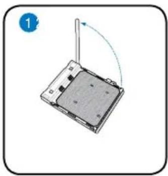
- Locate the CPU socket, then lift the socket lever to a 90° angle.
- Install the CPU to the socket, making sure that the CPU corner with the gold triangle matches the socket corner with a small triangle.
- Push down the socket lever to secure the CPU.
natural_image
Diagram of a device with a rotating cable and a base plate, showing no text or symbols
natural_image
Diagram of a wireless device with antenna and circular detail (no text or symbols)
natural_image
Diagram showing a computer monitor with an icon and magnified view of its screen (no text or symbols present)CAUTION: Incorrect installation of the CPU into the socket may bend the pins and severely damage the CPU!
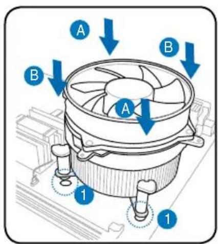
Installing the CPU fan and heatsink assembly Installing an Intel® Pentium® 4 CPU heatsink and fan
- Place the heatsink on top of the installed CPU, making sure that the four fasteners match the holes on the motherboard.
- Push down two fasteners at a time in a diagonal sequence to secure the heatsink and fan assembly in place.
- When the fan and heatsink assembly is in place, connect the CPU fan cable to the connector on the motherboard.
text_image
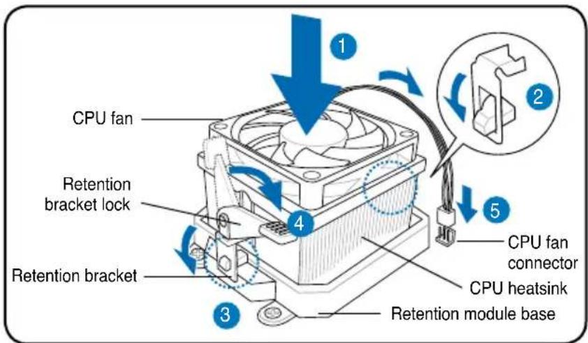
A B A B 1 1Installing an AMD CPU heatsink and fan
- Place the heatsink on top of the installed CPU.
IMPORTANT. Make sure that the fan and heatsink assembly perfectly fits the retention mechanism module base; otherwise you can not lock the retention bracket.
- Attach one end of the retention bracket to the retention module base.
- Attach the other end of the retention bracket (near the retention bracket lock) to the retention module base until it clicks in place.
NOTE. Your boxed CPU should come with installation instructions for the CPU, fan/heatsink assembly, and the retention mechanism. If the instructions in this section do not match the CPU documentation, follow the latter.
- Push down the retention bracket lock on the retention mechanism to secure the fan and heatsink to the module retention module base.
- Connect the CPU fan cable to the connector on the motherboard.
CAUTION. Do not forget to connect the CPU fan connector! Hardware monitoring error can occur if you fail to plug this connector.
text_image
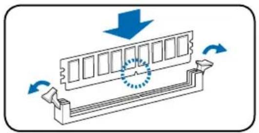
CPU fan Retention bracket lock Retention bracket CPU fan connector CPU heatsink Retention module baseInstalling a DIMM
- Locate the DIMM sockets in the motherboard.
- Unlock a DIMM socket by pressing the retaining clips outward.
- Align a DIMM on the socket such that the notch on the DIMM matches the break on the socket.
- Push the DIMM to the socket until the retaining clips snap inward.
natural_image
Diagram of a mechanical component with directional arrows indicating motion or force (no text or symbols)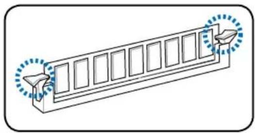
natural_image
Diagram of a 3D rectangular structure with window-like panels and two blue dotted arrows pointing to the right side (no text or symbols)CAUTION:
- Unplug the power supply before adding or removing DIMMs. Failure to do so may cause damage to the motherboard and/or components.
- A DDR DIMM is keyed with a notch so that it fits in only one direction. Do not force a DIMM into a socket to avoid damaging the DIMM.
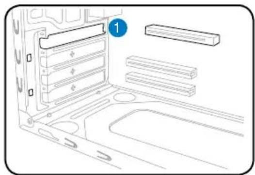
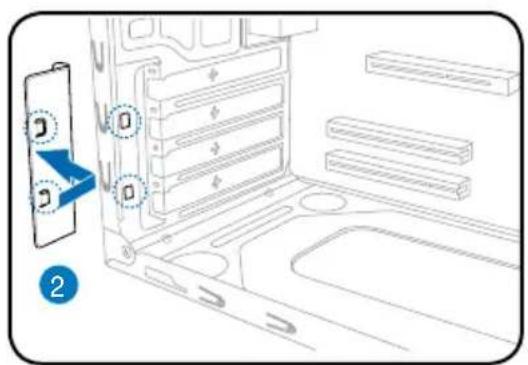
Installing an expansion card
the slot that you intend to use.
natural_image
Diagram of a computer tower case with labeled components (no text or symbols present)- Insert the card connector to the slot, then press the card firmly until it fits in place.
-
Replace the metal bracket lock.
-
Remove the metal bracket lock.1. Remove the metal
text_image
Diagram showing a device panel with labeled ports and directional arrows, likely illustrating a system or installation process.
text_image
Diagram showing a computer monitor with labeled parts and directional arrows indicating movement or assembly.Installing storage drives
Optical drive
- Place the chassis upright, then remove the upper 5.25" drive bay metal plate cover.
- Insert the optical drive to the bay, then carefully push the drive until its screw holes align with the holes on the bay.
- Secure the optical drive with two screws on both sides of the bay.
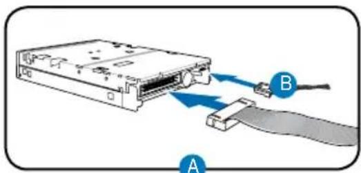
- Connect the IDE (A) and power (B) plugs to connectors at the back of the drive.
text_image
Diagram of a computer system with labeled components and directional arrows indicating flow or movement.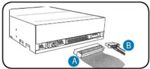
natural_image
Illustration of a computer drive with attached cable and connector (no text or symbols)Floppy disk drive
- Place the chassis upright, then remove the lower 3.5" drive bay metal plate cover.
- Insert the floppy disk drive to the bay, then carefully push the drive until its screw holes align with the holes on the bay.
- Secure the floppy disk drive with two screws on both sides of the bay.
- Connect the signal (A) and power (B) plugs to connectors at the back of the drive.
text_image
Diagram of a computer tower with labeled components and directional arrows indicating motion or signal flow.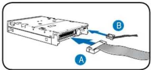
text_image
Diagram showing a computer drive with labeled components A and B, indicating cable or connection to the drive.Hard disk drive
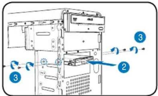
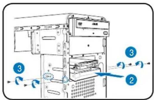
- Place the chassis upright, then remove the upper 3.5" drive bay metal plate cover.
- Insert the hard disk drive to the bay, then carefully push the drive until its screw holes align with the holes on the bay.
- Secure the hard disk drive with two screws on both sides of the bay.
text_image
Diagram of a computer tower with numbered annotations indicating components and directional arrows- For SATA HDD: Connect the SATA signal and power plugs to the connectors at the back of the drive.
For IDE HDD: Connect the IDE and power plugs to the connectors at the back of the drive.
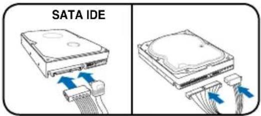
text_image
SATA IDERemoving the bay covers and reinstalling the front panel assembly and side cover
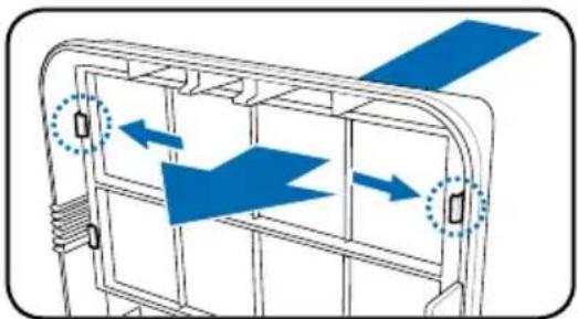
If you installed an optical and/or floppy disk drive, remove the bay cover(s) on the front panel assembly before reinstalling it to the chassis. To do this:
- Locate the bay cover locks.
- Press the locks outward to release the bay cover.
- Push the bay cover inward, then set it aside.
- Follow the same instructions to remove the 3.5" drive bay cover.
natural_image
Diagram of a mechanical or electrical component with blue arrows indicating direction, no text or symbols presentTo reinstall the front panel assembly and side cover:
- Insert the front panel assembly hinge-like tabs to the holes on the right side of the chassis.
- Swing the front panel assembly to the left, then insert the hooks to the chassis until the front panel assembly fits in place.
- Insert the six side cover hooks into the chassis tab holes.
- Push the side cover to the direction of the front panel until it fits in place.
- Secure the cover with two screws you removed earlier.
text_image
Air duct Chassis tab holesASUS
V-Série
natural_image
Line drawings of two different desktop computer cabinets, one labeled 'ASUS' and the other 'F5', showing front and side views without any text or symbols on the cabinet bodies.text_image
1 2 3 4 5 6 7 8 ASUtext_image
Diagram of a computer tower rear panel with numbered components and labeled connectorstext_image
Diagram of a computer rack with numbered components for identificationnatural_image
Diagram of a device with a switch and arrow indicating rotation (no text or symbols)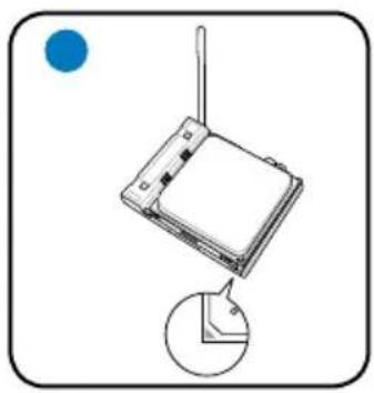
natural_image
Diagram of a device with a cable and a magnified view showing a small circular component (no text or symbols)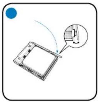
natural_image
Diagram showing a device with a magnified inset highlighting a component (no text or symbols present)natural_image
Diagram of a mechanical component with directional arrows indicating motion or force (no text or symbols)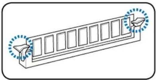
natural_image
Diagram of a structural beam with multiple supports and directional arrows indicating force or movement (no text or symbols)ATTENTION:
natural_image
Diagram of a computer chassis showing internal components and a numbered label (1), no text or symbols present.text_image
Diagram showing a device panel with labeled ports and directional arrows, likely illustrating a system or installation process.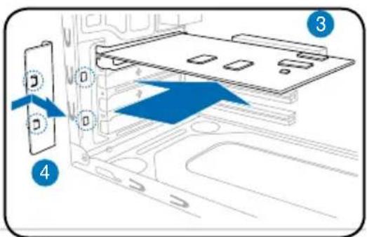
text_image
Diagram showing a device with labeled components and directional arrows indicating movement or flow, including numbered parts 3 and 4.text_image
Diagram of a computer monitor with labeled parts and directional arrows indicating motion or signal flow
natural_image
Illustration of a computer drive with labeled components A and B, showing internal components and a mesh texture (no text or symbols beyond labels)text_image
Technical diagram of a computer tower with numbered components and airflow indicators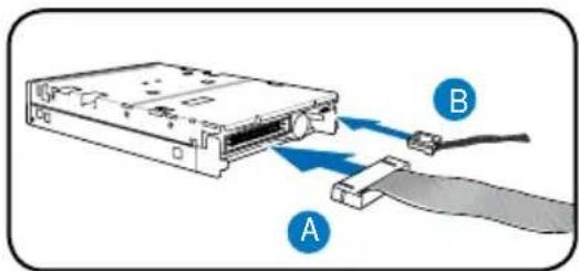
natural_image
Diagram of an electronic device showing a cable being inserted into a drive, labeled A and B (no text or symbols beyond labels)text_image
Diagram of a computer tower with numbered parts and directional arrows indicating movement or flownatural_image
Diagram of a mechanical or electrical component with blue arrows indicating direction, no text or symbols presentASUS PC (Desktop Barebone)
Installationshandbuch
natural_image
Line drawings of two different desktop computer cabinets, one labeled 'ASUS' and the other 'AS-US', showing front and side views without any text or symbols on the cabinet bodies.Frontseite
text_image
Diagram of a computer tower rear panel with numbered components and labeled connectorstext_image
Diagram of a computer rack with numbered components for identificationnatural_image
Diagram of a mechanical component with blue arrows indicating motion, showing internal structure and circular motion (no text or symbols)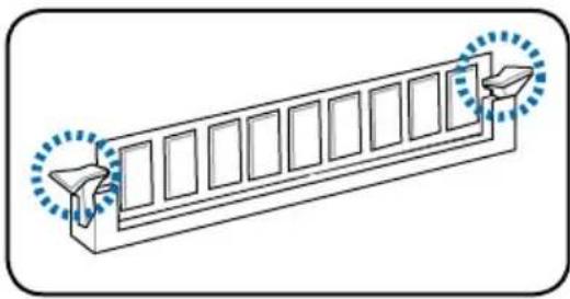
natural_image
Isometric line drawing of a structural beam with multiple supports and two circular annotations (no text or symbols)ACHTUNG:
natural_image
Diagram of a computer tower rear panel with labeled components (no text or symbols present)text_image
Diagram showing a device panel with labeled ports and directional arrows, likely illustrating a system or storage layout.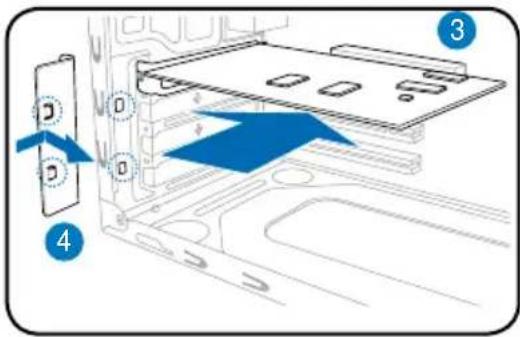
text_image
Diagram showing a device with labeled components and directional arrows indicating movement or flow, marked as 3 and 4.text_image
Diagram of a computer tower with labeled parts and directional arrows indicating flow or movement
natural_image
Illustration of an electronic device with labeled ports A and B, showing internal components and a meshed cable (no text or symbols beyond labels)Diskettenlaufwerk
text_image
Technical diagram of a server rack with labeled components and airflow indicators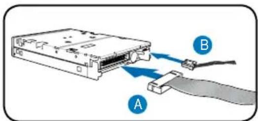
text_image
Diagram showing a computer drive with labeled components A and B, indicating cable or connector connection.Festplattenlaufwerk
text_image
Diagram of a computer tower with numbered parts and directional arrows indicating movement or system flownatural_image
Diagram of a mechanical component with blue arrows indicating direction, no text or symbols presentASUS PC (Desktop Barebone)
natural_image
Line drawings of two different desktop computer cabinets, one labeled 'ASUS' and the other 'AS-US', showing front and side views without any text or symbols on the cabinet bodies.text_image
Diagram of a computer tower rear panel with numbered components and labeled connectorstext_image
Diagram of a server rack with numbered components for identificationnatural_image
Diagram of a computer monitor with a stand and scroll, showing a curved arrow indicating rotation (no text or symbols present)
natural_image
Diagram of a wireless router with antenna and cable, showing a close-up view of its internal structure (no text or symbols)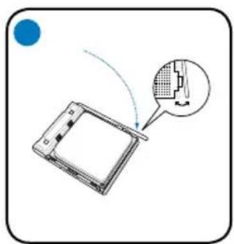
natural_image
Diagram showing a device with a magnified inset highlighting internal components (no text or symbols present)natural_image
Diagram of a mechanical component with blue arrows indicating motion or force, showing internal structure and rotation (no text or symbols)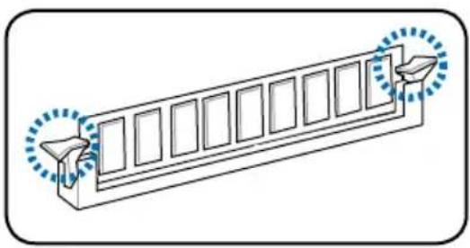
natural_image
Diagram of a 3D rectangular structure with internal compartments and two directional arrows indicating flow or movement (no text or symbols)ATTENZIONE.
natural_image
Diagram of a computer chassis showing internal components and storage areas (no text or symbols)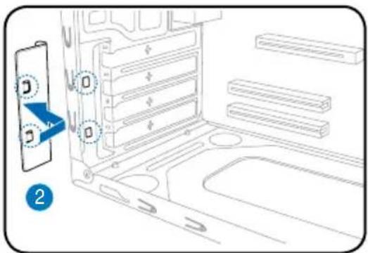
text_image
Diagram showing a device panel with labeled ports and directional arrows, likely illustrating a system or installation process.text_image
Diagram showing a device with labeled components and directional arrows indicating movement or flow, numbered 3 and 4.text_image
Diagram of a computer tower with numbered components and directional arrows indicating motion or flow
natural_image
Illustration of an electronic device with labeled components A and B, showing internal wiring and a connector (no text or symbols beyond labels)Lettore floppy
text_image
Diagram showing a computer drive with labeled components A and B, indicating cable connection or data transfer.Disco fisso
text_image
Diagram of a computer tower with numbered components and directional arrows indicating movement or flownatural_image
Diagram of a mechanical or electrical component with blue arrows indicating direction, no text or symbols presentnatural_image
Line drawings of two different desktop computer cabinets, one labeled 'ASUS' and the other 'AS-US', showing front and side views without any text or symbols on the cabinet bodies.text_image
Diagram of a computer tower rear panel with numbered components and labeled connectorstext_image
Diagram of a server rack with numbered components for identificationnatural_image
Diagram of a mechanical component with blue arrows indicating motion or force, showing internal structure and rotation (no text or symbols)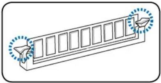
natural_image
Diagram of a mechanical component with multiple slots and two directional arrows, no text or symbols presentADVERTENCIA:
natural_image
Diagram of a computer tower rear panel with labeled components (no text or symbols present)text_image
Diagram showing a device panel with labeled ports and directional arrows, likely illustrating a system or storage layout.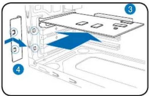
text_image
Diagram showing a device with labeled components and directional arrows indicating movement or flow, including numbered parts 3 and 4.text_image
Diagram of a computer tower with labeled components and directional arrows indicating motion or flow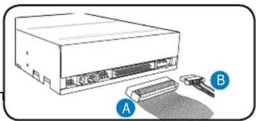
natural_image
Illustration of a computer drive with two labeled components (A and B), no text or symbols present.Unidad de disquete
text_image
Diagram of a computer tower with labeled parts and directional arrows indicating movement or flow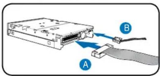
text_image
Diagram showing a computer drive with labeled components A and B, indicating internal connections or data flow.text_image
Diagram of a computer tower with numbered annotations indicating internal components and directional arrowsnatural_image
Diagram of a mechanical or electronic component with blue directional arrows indicating flow or movement (no text or symbols)natural_image
Line drawings of two different desktop computer cabinets, one labeled 'ASUS' and the other 'AS-US', showing front and side views without any text or symbols on the cabinet bodies.text_image
Diagram of a computer tower rear panel with numbered components and labeled connectorstext_image
Technical diagram of a server rack with numbered components for identificationnatural_image
Diagram of a mechanical component with blue arrows indicating motion or force, showing internal structure and circular motion (no text or symbols)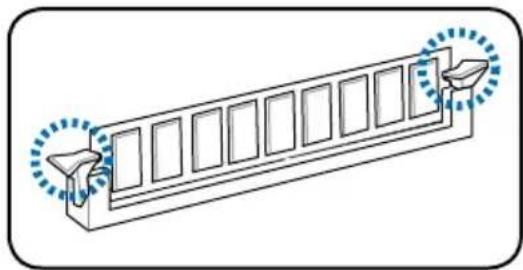
natural_image
Diagram of a mechanical component with multiple slots and two circular features, no text or symbols presentВНИМАНИЕ:
natural_image
Diagram of a computer tower case with labeled components and a numbered marker (1), showing internal storage areas and casing layout.text_image
Technical diagram showing a device with labeled components and a blue arrow pointing to a component with 'D' and 'O'.
text_image
Diagram showing device mounting process with labeled components and directional arrows indicating movement or assembly.text_image
Diagram of a computer tower with labeled components and directional arrows indicating flow or movement.
text_image
A BДисковод
text_image
Diagram of a server rack with labeled components and directional arrows indicating flow or movement
text_image
Diagram showing a computer drive with labeled components A and B, indicating internal components and cable connection.Жесткий диск
text_image
Diagram of a computer tower with numbered components and directional arrows indicating movement or flownatural_image
Diagram of a mechanical device with blue arrows indicating directional flow or movement, no text or symbols presentnatural_image
Line drawings of two different desktop computer cabinets, one labeled 'ASUS' and the other 'AS-US', showing front and side views without any text or symbols on the cabinet bodies.Características do painel frontal
text_image
Diagram of a computer tower rear panel with numbered components and labeled connectorstext_image
Diagram of a computer rack cabinet with numbered components for identificationnatural_image
Diagram of a mechanical component with directional arrows indicating motion or flow (no text or symbols)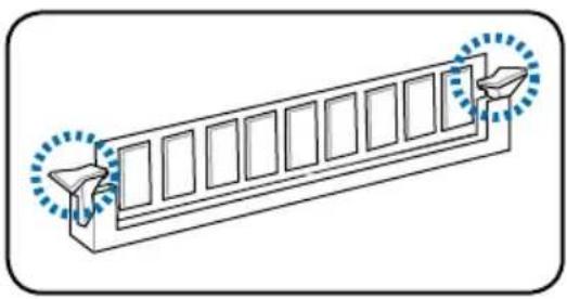
natural_image
Diagram of a rectangular structure with window-like panels and two blue dotted arrows pointing to the right side (no text or symbols)ATENÇÃO.
natural_image
Diagram of a computer tower panel with labeled components (no text or symbols present)text_image
Diagram showing a device panel with labeled buttons and directional arrows, likely illustrating a system or installation process.
text_image
Diagram showing a device with labeled components and directional arrows indicating movement or flow, numbered 3 and 4.text_image
Diagram of a computer tower with labeled parts and directional arrows indicating motion or signal flow
natural_image
Illustration of a computer drive with labeled components A and B, showing internal components and a mesh cable (no text or symbols beyond labels)text_image
Diagram of a server rack with labeled components and airflow indicators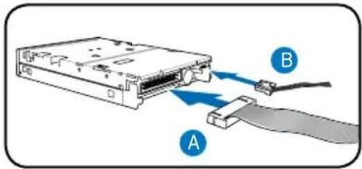
text_image
Diagram showing a computer drive with labeled components A and B, indicating cable connection or data transfer.text_image
Diagram of a computer tower with numbered annotations indicating internal components and directional arrowsnatural_image
Line drawings of two different desktop computer cabinets, one labeled 'ASLS' and the other 'FBS', showing front and side views without any text or symbols on the cabinet bodies.text_image
Diagram of a computer tower rear panel with numbered components and labeled connectorstext_image
Diagram of a computer rack with numbered components for identificationtext_image
Diagram illustrating three steps of a device's internal structure and component insertion, with Chinese annotations.natural_image
Diagram of a mechanical component with directional arrows indicating motion or force (no text or symbols)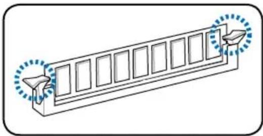
natural_image
Diagram of a structural beam with multiple supports and two circular annotations (no text or symbols)UPOZORNĚNÍ.
natural_image
Diagram of a computer tower case with labeled components and a numbered marker (1), showing internal storage areas and casing layout.text_image
Diagram showing a device panel with labeled ports and directional arrows, likely illustrating a system or installation process.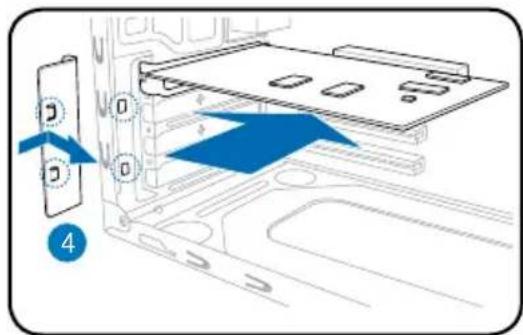
text_image
Diagram showing a device with labeled components and directional arrows indicating movement or flow, including a blue arrow pointing to a component.text_image
Diagram of a computer tower with numbered components and directional arrows indicating motion or flow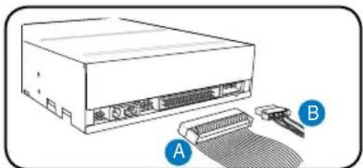
text_image
电源 A BDisketová jednotka
text_image
Diagram of a computer tower with numbered components and directional arrows indicating flow or movement
natural_image
Diagram of a computer drive with labeled components A and B, showing internal components connected to a cable (no text or symbols beyond labels)Pevný disk
text_image
Diagram of a computer tower with labeled parts and directional arrows indicating movement or flownatural_image
Diagram of a mechanical or electronic component with blue arrows indicating direction, no text or symbols presentnatural_image
Line drawings of two different desktop computer cabinets, one labeled 'ASUS' and the other 'F5', showing front and side views without any text or symbols on the cabinet bodies.text_image
Diagram of a computer tower rear panel with numbered components and labeled connectorstext_image
Diagram of a server rack with numbered components for identificationtext_image
Diagram illustrating three steps of a device's internal structure and component insertion, with Chinese labels.natural_image
Diagram of a mechanical component with directional arrows indicating motion or flow (no text or symbols)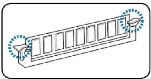
natural_image
Diagram of a structural beam with multiple supports and two directional arrows indicating force or movement (no text or symbols)UWAGA.
natural_image
Diagram of a computer tower internal structure with labeled component (no text or symbols present)text_image
Diagram showing a device panel with labeled components and a blue arrow indicating a directional change or movement.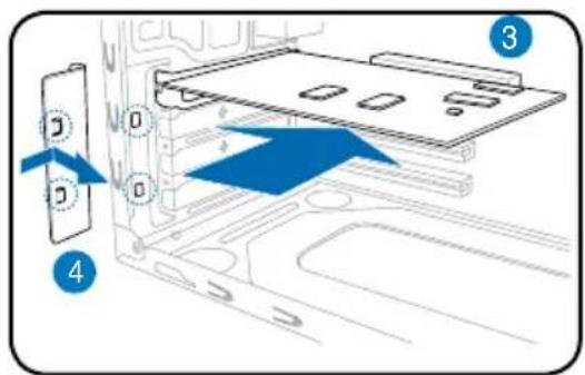
text_image
Diagram showing a device with labeled components and directional arrows indicating movement or flow, numbered 3 and 4.text_image
Diagram of a computer tower with numbered components and directional arrows indicating motion or movement.
natural_image
Illustration of a computer drive with labeled components A and B, showing internal components and a cable attachment (no text or symbols beyond labels)text_image
Diagram of a server rack with labeled components and airflow indicators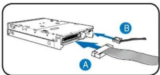
text_image
Diagram showing a computer drive with labeled components A and B, indicating internal components connected to a cable.text_image
Diagram of a computer tower with numbered components and directional arrows indicating movement or flownatural_image
Diagram of a vehicle door frame with blue directional arrows indicating movement or flow (no text or symbols)natural_image
Line drawings of two different desktop computer cabinets, one labeled 'ASUS' and the other 'AS-US', showing front and side views without any text or symbols on the cabinet bodies.Az előlap elemei
text_image
Diagram of a computer tower rear panel with numbered components and labeled connectorstext_image
Diagram of a computer rack with numbered components for identificationnatural_image
Diagram of a mechanical component with directional arrows indicating motion or force (no text or symbols)
natural_image
Diagram of a mechanical component with multiple slots and two circular features, no text or symbols presentFIGYELEM!
natural_image
Diagram of a computer tower case with labeled components (no text or symbols present)text_image
Diagram showing a device interior with labeled ports and a blue arrow pointing to a device panel with 'D' and 'O'.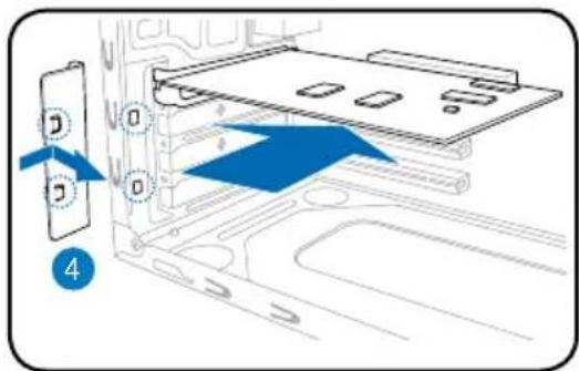
text_image
Diagram showing a device with labeled components and directional arrows indicating movement or flow, marked with number 4.text_image
Diagram of a computer rack with labeled parts and directional arrows indicating motion or signal flow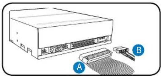
natural_image
Illustration of a computer drive with labeled components A and B, showing internal components and a mesh cable (no text or symbols beyond labels)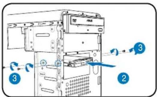
text_image
Diagram of a server rack with labeled components and directional arrows indicating movement or flow