
128PS - Saw HUSQVARNA - Free user manual and instructions
Find the device manual for free 128PS HUSQVARNA in PDF.
| Product type | Pole saw (pruner on pole) |
| Brand / Model | Husqvarna 128PS |
| Displacement | 28 cm³ (1.7 cu in) |
| Max power | 0.7 kW (0.94 hp) at 8500 rpm |
| Idle speed | 2300 – 3200 rpm |
| Recommended max speed | 8000 rpm |
| Fuel tank capacity | 0.4 L (0.85 US pt) |
| Chain oil tank capacity | 0.14 L (0.3 US pt) |
| Weight (without fuel and accessories) | 6.4 kg (14.2 lb) |
| Guide bar length | 20 cm (8 in) |
| Chain pitch | 3/8 in |
| Chain gauge | 0.043 in (1.1 mm) |
| Spark plug | Champion RCJ 8Y, gap 0.61 mm |
| Catalytic muffler | Yes |
| Engine type | 2-stroke, air-cooled |
| Fuel supply | Unleaded gasoline - 2-stroke oil mixture (50:1) |
| Ignition system | Electronic |
| Main features | Easy start, primer bulb, choke, chain oil flow adjustment |
| Safety | Throttle trigger lock, stop switch, chain brake at idle, hand guard |
| Routine maintenance | Air filter cleaning, spark plug check, cooling system cleaning, chain sharpening and tensioning |
| Optional accessories | Hedge trimmer, brush cutter, edger, cultivator, blower |
| Intended use | Trimming branches and twigs |
Frequently Asked Questions - 128PS HUSQVARNA
User questions about 128PS HUSQVARNA
0 question about this device. Answer the ones you know or ask your own.
Ask a new question about this device
Download the instructions for your Saw in PDF format for free! Find your manual 128PS - HUSQVARNA and take your electronic device back in hand. On this page are published all the documents necessary for the use of your device. 128PS by HUSQVARNA.
USER MANUAL 128PS HUSQVARNA
natural_image
Silhouette of a selfie stick with a handle and wristband (no text or symbols)128PS
EN Operator's manual 2-24
Transportation, storage and disposal....22
Technical data....23
Accessories....23
Introduction
Intended use
The product is used for cutting branches and twigs.
Note: National regulations can set limit to the operation of the product.
Only use the product with accessories that are approved by the manufacturer. Refer to Accessories on page 23.
Product overview
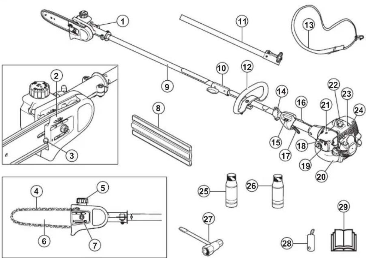
-
Chain lubrication adjustment screw
-
Protective guard for saw chain
-
Chain tensioning screw
-
Saw chain
-
Chain oil tank
-
Guide bar
-
Bar nut
-
Transport guard, bar
-
Shaft
-
Shaft coupling
-
Extension shaft
-
Front handle
-
Harness
-
Harness support hook
-
Stop switch
-
Throttle trigger lockout
-
Throttle trigger
-
Choke control
-
Air purge
-
Fuel tank
-
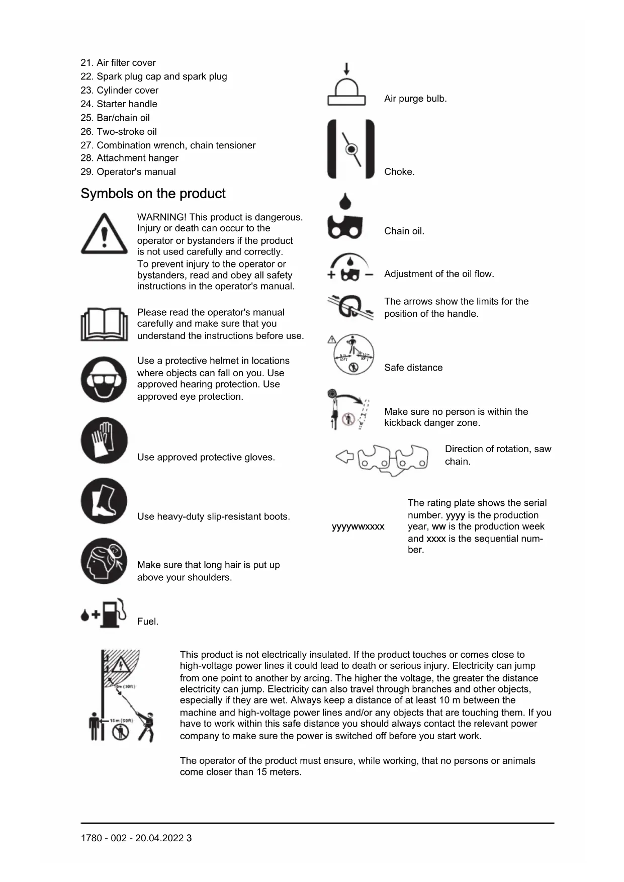
Air filter cover
- Spark plug cap and spark plug
- Cylinder cover
- Starter handle
- Bar/chain oil
- Two-stroke oil
- Combination wrench, chain tensioner
- Attachment hanger
- Operator's manual
Symbols on the product

WARNING! This product is dangerous. Injury or death can occur to the operator or bystanders if the product is not used carefully and correctly. To prevent injury to the operator or bystanders, read and obey all safety instructions in the operator's manual.

Please read the operator's manual carefully and make sure that you understand the instructions before use.

Use a protective helmet in locations where objects can fall on you. Use approved hearing protection. Use approved eye protection.

Use approved protective gloves.

Use heavy-duty slip-resistant boots.

Make sure that long hair is put up above your shoulders.

Fuel.
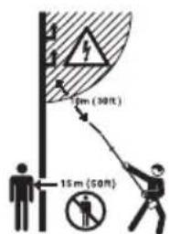
This product is not electrically insulated. If the product touches or comes close to high-voltage power lines it could lead to death or serious injury. Electricity can jump from one point to another by arcing. The higher the voltage, the greater the distance electricity can jump. Electricity can also travel through branches and other objects, especially if they are wet. Always keep a distance of at least 10 m between the machine and high-voltage power lines and/or any objects that are touching them. If you have to work within this safe distance you should always contact the relevant power company to make sure the power is switched off before you start work.
The operator of the product must ensure, while working, that no persons or animals come closer than 15 meters.

Air purge bulb.

Choke.

Chain oil.

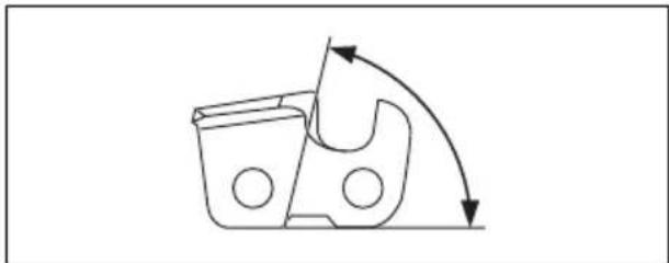
Adjustment of the oil flow.

The arrows show the limits for the position of the handle.

Safe distance

Make sure no person is within the kickback danger zone.
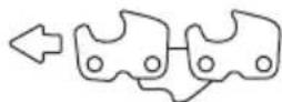
Direction of rotation, saw chain.
yyyyMMddxxxx
The rating plate shows the serial number. yyyy is the production year, ww is the production week and xxxx is the sequential number.
Note: Other symbols/decals on the product refer to certification requirements for other commercial areas.
EPA III
![EMISSION CONTROL INFORMATION THIS ENGINE MEETS EXH AND EVP EMISSIONS REGULATIONS FOR [__ SMALL OFFROAD ENGINES] [________________________________________________________________________________________________________________________________________________________________________________________________________________________________________________________________________________________________________________% FAMILY/DISP PLT# [__ SKU#] [__________________________________________ EMISSION COMPLIANCE PERIOD SN: [________________________________ REFER TO OWNER'S MANUAL FOR MAINTENANCE SPECIFICATIONS AND ADJUSTMENTS.](/content/2026/04/617018/images/db4aa6ab79d711071e9ff0f8ac78e2352b6d4f1aa964710ad8b83d68ed150fd6.jpg)
The Emissions Compliance Period referred to on the Emission Compliance label indicates the number of operating hours for which the engine has been shown to meet Federal and California emissions requirements.
| EMISSION CONTROL LABEL ABBREVIATIONS | |||||
| General Exhaust emission control systems Evaporative emission control systems | |||||
| ECS Emission control system | ECM Engine control module (Autotune) | C Coextruded (Multilayer) | |||
| EXH/EVP Exhaust and Evaporative | EM Engine modification N Nylon | ||||
| HRS Hours OC Oxidizing Catalyst P | Treated HDPE or PE | ||||
| REGS Regulations TWC Three way | catalyst S Sealed | ||||
| SORE Small off road engines | |||||
| US EPA | United States Environmental Protection Agency | ||||
| CAL | California | ||||
| EVAP | Evaporative | ||||
| DISPL Displacement | |||||
WARNING!
The engine exhaust from this product contains chemicals known to the State of California to cause cancer, birth defects or other reproductive harm.
Product liability
As referred to in the product liability laws, we are not liable for damages that our product causes if:
• the product is incorrectly repaired.
- the product is repaired with parts that are not from the manufacturer or not approved by the manufacturer.
- the product has an accessory that is not from the manufacturer or not approved by the manufacturer.
- the product is not repaired at an approved service center or by an approved authority.
Safety
Safety definitions
Warnings, cautions and notes are used to point out specially important parts of the manual.

WARNING: Used if there is a risk of injury or death for the operator or bystanders if the instructions in the manual are not obeyed.

CAUTION: Used if there is a risk of damage to the product, other materials or the adjacent area if the instructions in the manual are not obeyed.
Note: Used to give more information that is necessary in a given situation.
General safety instructions

WARNING: Read the warning instructions that follow before you use the product.
- This product produces an electromagnetic field during operation. This field may under some circumstances interfere with active or passive medical implants. To reduce the risk of serious or fatal injury we recommend persons with medical implants to consult their physician and the medical implant manufacturer before operating this product.
- This product is a dangerous tool if you are not careful or if you use the product incorrectly. This product can cause serious injury or death to the operator or others.
-
It is very important that you read and understand the contents of this operator's manual. If you feel uncertainty about a work situation or the operating procedures after you read the operator's manual, speak to a service agent before you continue.
-
Under no circumstances may the design of the product be modified without the permission of the manufacturer. Do not use a product that appears to have been modified by others and only use accessories recommended for this product. Non-authorized modifications and/or accessories can result in serious personal injury or the death of the operator or others.
- Do a check of the product before use. Refer to Safety devices on the product on page 7 and To check before starting on page 11. Do not use a defective product. Do the safety checks, maintenance and service instructions described in this manual.
Safety instructions for assembly

WARNING: Read, understand and obey these instructions carefully before you use the product.
- The complete clutch cover and shaft must be fitted before the machine is started, otherwise the clutch can come loose and cause personal injury.
- The only accessories you can operate with this product are the cutting attachments we recommend. Refer to Accessories on page 23.
- Use approved protective gloves.
- Make sure that you assemble the protective cover and shaft correctly before you start the engine.
• To operate the product safely and prevent injury to the operator or other persons, the product must always be attached correctly to the harness.
Safety instructions for operation

WARNING: Read the warning instructions that follow before you do maintenance on the product.
- Use personal protective equipment, refer to Personal protective equipment on page 6.
- This product is not electrically insulated. If the product touches or comes close to high-voltage power lines it could lead to death or serious bodily injury. Electricity can jump from one point to another by arcing. The higher the voltage, the greater the distance electricity can jump. Electricity can also travel through branches and other objects, especially if they are wet. Always keep a distance of at least 10 m between the product and high-voltage power lines and/or any objects that are touching them. If have to work within this safe distance you should always contact the relevant power company to make sure the power is switched off before you start work.
• Overexposure to vibration can lead to circulatory damage or nerve damage in persons who have poor circulation. Speak to your physician if you experience symptoms of overexposure to vibration. Such symptoms include numbness, loss of feeling, tingling, pricking, pain, loss of strength, changes in skin colour or condition. These symptoms usually show in the fingers, hands or wrists. The risk increases at low temperatures. - The inside of the muffler contain chemicals that may be carcinogenic. Avoid contact with these elements in the event of a damaged muffler. Long term inhalation of the engine's exhaust fumes, chain oil mist and sawdust can represent a health risk.
- Never use the machine indoors or in spaces lacking proper ventilation. Exhaust fumes contain carbon monoxide, an odourless, poisonous and highly dangerous gas.
- Do not operate a product without a muffler or with a defective muffler. A defective muffler can increase the noise level and the risk of fire. Keep fire extinguishing tools near. If you must have a spark arrestor mesh in your area, do not use the product without or with a broken spark arrestor mesh.
- If the saw chain does not stop when idling, adjust the idle speed. Refer to To adjust the idle speed on page 21. Do not use the product until it is correctly adjusted or repaired.
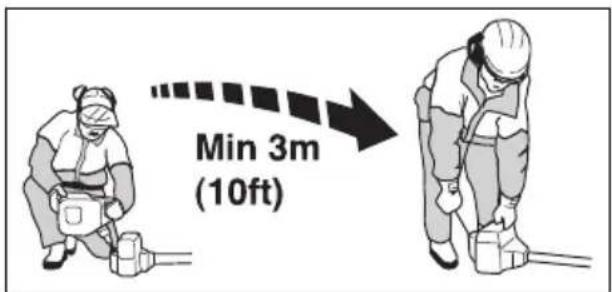
- This product has a long reach. Make sure that no people or animals come closer than 15 m when the product is running. Always look behind you before you turn around with the product. Stop the product immediately if a person or animal enters the 15 m safety zone. If more than one operator does work in the same area, keep a safety distance of a minimum of 15 m.
- Observe the applicable safety regulations for work in the vicinity of overhead power lines. Also falling branches can result in short-circuiting.
- Never stand directly underneath a branch that is being cut. This could lead to serious or even fatal personal injury.
- Watch out for stumps of branches that can be thrown out when you cut. Do not cut too close to
the ground where stones and other objects can be thrown out.
- Do not operate the product in bad weather, such as dense fog, heavy rain, strong wind and intense cold. To operate in bad weather can make you tired and add risks, such as icy ground and unpredictable felling direction.
- Do not use the product if you are tired, ill, or under the influence of alcohol, drugs or medicine, as this has a negative effect on your vision, alertness, coordination and judgment.
- Make sure that you can move safely and have a safe stance. Examine the area around you for obstacles such as roots, rocks, branch and ditches. Be careful during work on slopes.
- Do not remove the cut material, or let other persons remove cut material, while the engine is on or the cutting equipment rotates, as this can result in serious injury.
- Do not overreach. Keep a stable position of the feet and a good balance at all times.
- Always hold the product with both hands. Hold the product on the right side of your body.

natural_image
Line drawing of a person in protective gear holding a long pole (no text or symbols)- Keep your hands and feet away from the saw chain until it has stopped completely when the product is deactivated.
- Never work from a ladder, stool or any other raised position that is not fully secured.
- Do not put the product down with the engine on unless you have it in clear view.
- Listen for warning signals and loud voices when you use hearing protection. Always remove your hearing protection when the engine stops.
- Stop the engine before you move to a new work area. Always attach the transport guard before you move the equipment.
- Never allow children to use or be in the vicinity of the product. Remove the spark plug cap when the product is not under close supervision.
Personal protective equipment

WARNING: Read the warning instructions that follow before you use the product.
• Always use approved personal protective equipment when you use the product. Personal protective equipment cannot fully prevent injury but it decreases the degree of injury if an
accident does occur. Let your dealer help you select the right equipment.
- Use a protective helmet where there is a risk of falling objects.
- Use approved hearing protection that provides adequate noise reduction. Long-term exposure to noise can result in permanent hearing impairment.
- Use approved eye protection. If you use a visor, you must also use approved protective goggles. Approved protective goggles must comply with the ANSI Z87.1 standard in the USA or EN 166 in EU countries.
- Use a visor for face protection. A visor is not enough for protection of the eyes.

- Use gloves when necessary, for example when you attach, examine or clean the cutting equipment.
- Use sturdy non-slip boots.
- Use clothing made of a strong fabric. Always use heavy, long pants and long sleeves. Do not use loose clothing that can catch on twigs and branches. Do not wear jewelry, short pants, sandals or go with bare feet. Put your hair up safely above shoulder level.


- Keep first aid equipment close at hand.

Safety devices on the product

WARNING: Read the warning instructions that follow before you use the product.
- Do not use a product with defective safety devices.
- Do a check of the safety devices regularly. Refer to Maintenance schedule on page 15.
- If the safety devices are defective, speak to your Husqvarna servicing dealer.
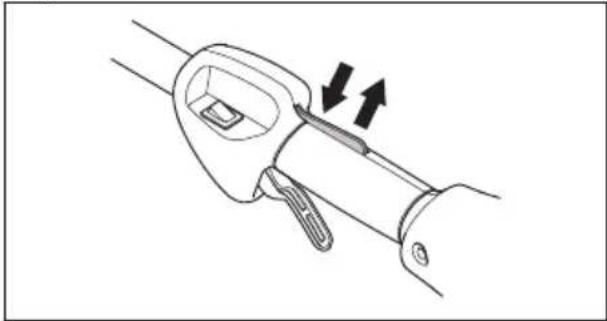
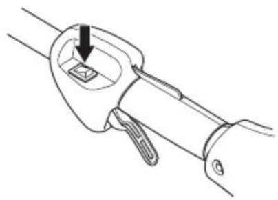
To do a check of the throttle trigger lockout
- Make sure that the throttle trigger lockout (A) and throttle trigger (B) move freely and that the return spring works correctly.

- Push down the throttle trigger lockout and make sure that it goes back to its initial position when you release it.
natural_image
Diagram of a mechanical lever mechanism with two arrows indicating motion direction (no text or symbols)- Make sure that the throttle trigger is locked at the idle position when the throttle trigger lockout is released.
natural_image
Line drawing of a mechanical device with a lever and adjustment arrow (no text or symbols)- Start the product and apply full throttle.
- Release the throttle trigger and make sure that the saw chain stops and stay stationary.

WARNING: If the saw chain moves when the throttle trigger is in the idle position, then the carburetor idle speed must be adjusted. Refer to To adjust the idle speed on page 21.
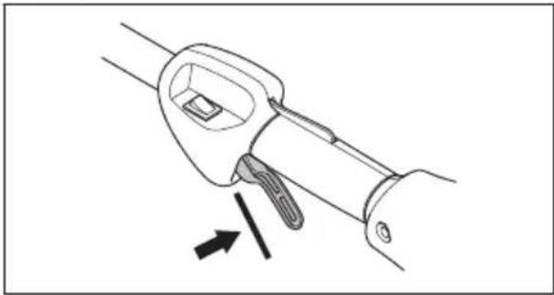
To do a check of the stop switch
-
Start the engine.
-
Move the stop switch to the stop position and make sure that the engine stops.

natural_image
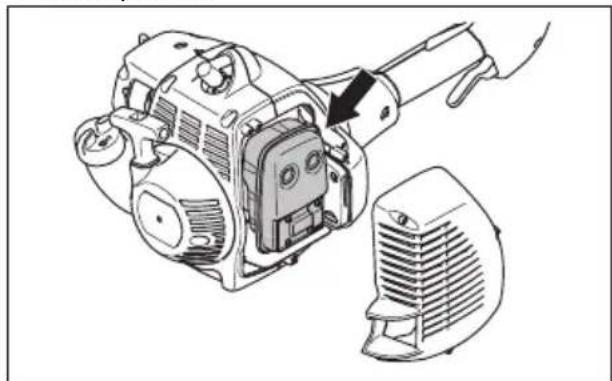
Line drawing of a mechanical tool with a handle and base, showing a step indicator (no text or symbols present)To do a check of the muffler

WARNING: Do not use a product that has a defective muffler.

WARNING: Do not use the product if the spark arrester screen on the muffler is missing or defective.

WARNING: The muffler becomes very hot during and after operation and also at idle speed. Use protective gloves to prevent burn injuries.
The muffler keeps noise levels to a minimum and points exhaust fumes away from the operator.
- Stop the engine.
- Examine the muffler for damage and defects.

WARNING: The inner surfaces of the muffler contain chemicals that can cause cancer. Be careful not to touch these elements if the muffler is damaged.
- Make sure that the muffler is correctly attached to the product.
natural_image
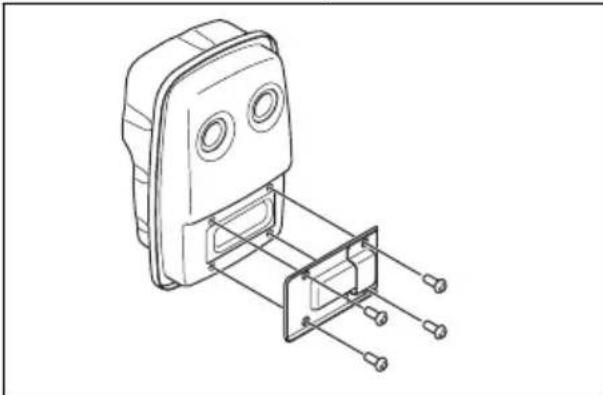
Technical line drawing of a mechanical device with an arrow indicating a component (no text or symbols present)- Do a visual check of the spark arrester screen.
natural_image
Technical line drawing of a mechanical component with mounting holes and internal structure (no text or symbols)a) Replace the spark arrester screen if it is damaged.
b) Clean the spark arrester screen if it is blocked.

CAUTION: If the spark arrester screen is blocked the product becomes too hot and this causes damage to the cylinder and piston.
Fuel safety

WARNING: Read the warning instructions that follow before you use the product.
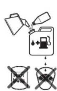
- Do not mix the fuel indoor or near a heat source.
- Do not start the product if there is fuel or engine oil on the product. Remove the unwanted fuel/oil and let the product dry. Remove unwanted fuel from the product.
- If you spill fuel on your clothing, change clothing immediately.
- Do not get fuel on your body, it can cause injury. If you get fuel on your body, use a soap and water to remove the fuel.
- Do not start the engine if you spill oil or fuel on the product or on your body.
- Do not start the product if the engine has a leak. Examine the engine for leaks regularly.
- Be careful with fuel. Fuel is flammable and the fumes are explosive and can cause injuries or death.
- Do not breathe in the fuel fumes, it can cause injury. Make sure that there is sufficient airflow.
- Do not smoke near the fuel or the engine.
- Do not put warm objects near the fuel or the engine.
- Do not add the fuel when the engine is on.
• Make sure that the engine is cool before you refuel. - Before you refuel, open the fuel tank cap slowly and release the pressure carefully.
• Make sure there are sufficient airflow when refueling and mixing fuel (petrol and two-stroke oil) or draining the fuel tank.
- Fuel and fuel vapor are highly flammable and can cause serious injury when inhaled or allowed to come into contact with the skin. For this reason, observe caution when handling fuel and make sure there is sufficient airflow.
- Tighten the fuel tank cap carefully or a fire can occur.
- Move the product at a minimum of 3 m (10 ft) from the position where you filled the tank before a start.
- Do not put too much fuel in the fuel tank.
• Make sure that a leak cannot occur when you move the product or fuel container.
- Do not put the product or a fuel container where there is an open flame, spark or pilot light. Make sure that the storage area does not contain an open flame.
- Only use approved containers when you move the fuel or put the fuel into storage.
- Empty the fuel tank before long-term storage. Obey the local law on where to dispose fuel.
- Clean the product before long-term storage.
- Remove the spark plug cap before you put the product into storage to make sure that the engine does not start accidentally.
Safety instructions for maintenance

WARNING: Read the warning instructions that follow before you do maintenance on the product.
- Do only the maintenance and servicing given in this operator's manual. Let professional servicing personnel do all other servicing and repairs.
- Regularly do the safety checks, maintenance and service instructions given in this manual. Regular maintenance increases the life of the product and decreases the risk of accidents. Refer to Maintenance on page 15 for instructions.
- If the safety checks in this operator's manual is not approved after you do maintenance, speak to your servicing dealer. We guarantee that there are professional repairs and servicing available for your product.
Safety instructions for the cutting equipment

WARNING: Read the warning instructions that follow before you use the product.
- Only use the guide bar/saw chain combinations and filing equipment that we recommend. Refer to Accessories on page 23 for instructions.
- Use protective gloves when you use or do maintenance on the saw chain. A saw chain that does not move can also cause injuries.
- Keep the cutting teeth correctly sharpened. Obey the instructions and use the recommended file gauge. A saw chain that is damaged or incorrectly sharpened increases the risk of accidents.
- Keep the correct depth gauge setting. Obey the instructions and use the recommended depth gauge setting.
natural_image
Pure technical line drawing of a mechanical component with no text or symbols• Make sure that the saw chain has the correct tension. If the saw chain is not tight against the guide bar, the saw chain can derail. An incorrect saw chain tension increases wear on the guide bar, saw chain and chain drive sprocket. Refer to To adjust the chain tension on page 16.
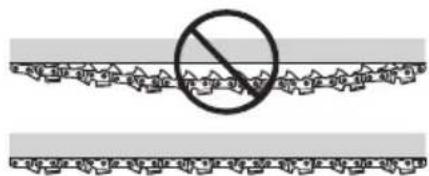
- Do maintenance on the cutting equipment regularly and keep it correctly lubricated. If the saw chain is not correctly lubricated, the risk of wear on the guide bar, saw chain and chain drive sprocket increases.

natural_image
Simple line drawing of a droplet falling from a container with two circular ends (no text or symbols)Assembly
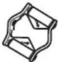
To attach the loop handle
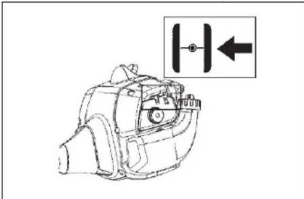
- Attach the loop handle to the shaft in compliance with the illustration and tighten.
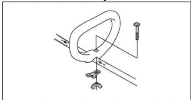
natural_image
Technical line drawing of a mechanical clamp or bracket assembly (no text or symbols)- Make sure that the loop handle attaches between the arrows on the shaft.
To assemble the two-piece shaft
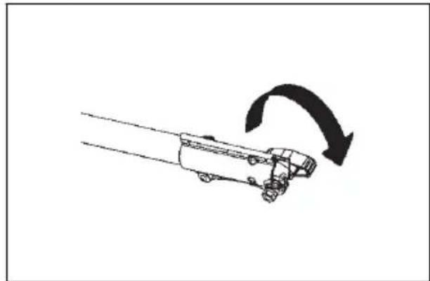
- Turn the knob to loosen the shaft coupling.

natural_image
Diagram of a truck with an arrow indicating clockwise motion (no text or symbols)- Move the locking/release button (A) into the guide recess. Push the attachment into the coupler until the locking/release button sets into the primary hole (B).
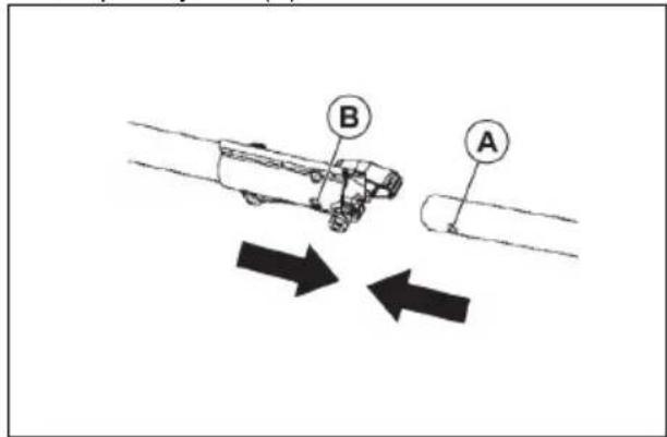
- Insert the shaft into the shaft coupling. The button must go through the hole.
Note: If the attachment does not go fully into the upper shaft, use a small screwdriver to push the internal drive shaft deeper into the tube. It can be necessary to turn the screwdriver while you push.
- Make sure that you fully tighten the knob before you operate the product.

natural_image
Simple line drawing of a truck on a road with an arrow indicating clockwise motion (no text or symbols)To attach the pole saw attachment

WARNING: Stop the product on a level surface when you install or remove the attachments.
- Turn the knob counterclockwise and loosen the coupler on the extension shaft.
natural_image
Diagram of a truck with an arrow indicating clockwise motion (no text or symbols)- Remove the transport guard from the coupler.
- Remove the shaft cap from the attachment.
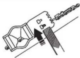
- Move the locking/release button into the guide recess.
- Push the attachment into the coupler until the locking/release button sets into the primary hole.
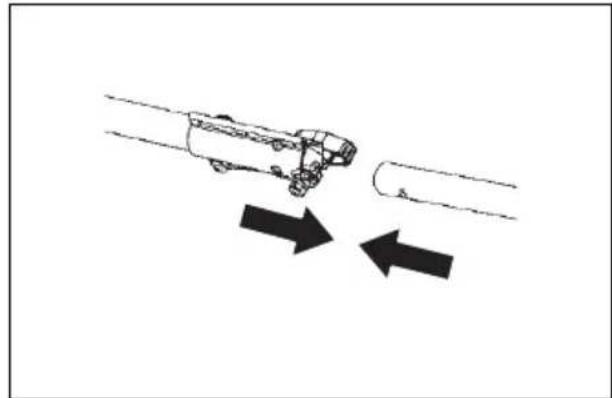
natural_image
Diagram showing a vehicle moving on a road with two opposing arrows indicating direction (no text or symbols)-
Do steps1 through 5 again to attach the other attachment on the engine shaft.
-
Turn the knobs on the extension shaft and the engine shaft clockwise and tighten them.

natural_image
Simple line drawing of a car on a road with an arrow indicating clockwise motion (no text or symbols)- Tighten the couplers on the extension shaft and the engine shaft.
To adjust the harness
You should always use the harness with the machine to give maximum control over the machine and reduce the risk of fatigue in your arms and back.
- Put on the harness.
- Hook the machine onto the harness support hook.
- Adjust the length of the harness so that the support hook is roughly level with your right hip.
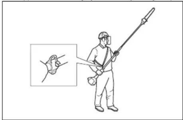
natural_image
Illustration of a person in protective gear using a long-handled tool, with an inset showing a close-up of the hand holding a ring (no text or symbols present)To disassemble the two-piece shaft
- Turn the knob to loosen the shaft coupling.

natural_image
Diagram of a car on a road with an arrow indicating clockwise motion (no text or symbols)- Push and hold the locking/release button (B). Pull the shafts apart.

Operation
Introduction

WARNING: Before you operate the product, you must read and understand the safety chapter.
To check before starting
- Inspect the working area. Remove any objects that could be thrown out.
- Check the saw chain. Never use blunt, cracked or damaged equipment.
- Check that the product is in perfect working order.
-
Check that all nuts and screws are tight.
-
Make sure the chain is adequately lubricated, refer to To check the chain lubrication on page 20.
- Check that the saw chain always stops when the engine is idling.
- Only use the product for the purpose it was intended for.
- Make sure the handle and safety features are in order. Never use a machine that has any parts missing or has been modified in relation to the specification.
Fuel
This product has a two-stroke engine.

CAUTION: Incorrect type of fuel can result in engine damage. Use a mixture of gasoline and two-stroke oil.
Premixed fuel
- Use Husqvarna premixed alkylate fuel for best performance and extension of the engine life. This fuel contains less harmful chemicals compared to regular fuel, which decreases harmful exhaust fumes. The quantity of remains after combustion is lower with this fuel, which keeps the components of the engine more clean.
To mix fuel
Gasoline

CAUTION: Do not use gasoline with an octane number less than 90 RON (87 AKI). This can cause damage to the product.

CAUTION: Do not use gasoline with more than 10% ethanol concentration (E10). This can cause damage to the product.

CAUTION: Do not use leaded gasoline. This can cause damage to the product.
• Always use new unleaded gasoline with a minimum octane number of 90 RON (87 AKI) and with less than 10% ethanol concentration (E10).
- Use gasoline with a higher octane number if you frequently use the product at continuously high engine speed.
• Always use a good quality unleaded gasoline/oil mixture.
Two-stroke oil
- For best results and performance use Husqvarna two-stroke oil.
- If Husqvarna two-stroke oil is not available, use a two-stroke oil of good quality for air-cooled engines. Speak to your servicing dealer to select the correct oil.

CAUTION: Do not use two-stroke oil for water-cooled outboard engines, also referred to as outboard oil. Do not use oil for four-stroke engines.
To mix gasoline and two-stroke oil
| Gasoline, liter Two-stroke | oil, liter |
| 2% (50:1) | |
| 5 0.10 | |
| 10 0.20 | |
| 15 0.30 | |
| 20 0.40 |

CAUTION: Small errors can influence the ratio of the mixture drastically when you mix small quantities of fuel. Measure the quantity of oil carefully and make sure that you get the correct mixture.

natural_image
Illustration of a person in military-style attire holding an object, no text or symbols present- Fill half the quantity of gasoline in a clean container for fuel.
- Add the full quantity of oil.
- Shake the fuel mixture.
- Add the remaining quantity of gasoline to the container.
- Carefully shake the fuel mixture.

CAUTION: Do not mix fuel for more than 1 month at a time.
To fill the fuel tank
- Clean the area around the fuel tank cap.
- Shake the container and make sure that the fuel is fully mixed. Use a fuel container with an anti-spill valve.
- Fill the fuel tank.
- Tighten the fuel tank cap carefully.
- Move the product 3 m (10 ft) or more away from the refueling area and fuel source before starting.

CAUTION: Contamination in the tanks causes malfunction. Clean the fuel tank and chain oil tank regularly and replace the fuel filter one time a year or more.
To do a run-in
- During the first 10 hours of operation, do not apply full throttle without load for extended periods.
To use the correct chain oil

WARNING: Do not use waste oil, which can cause injury to you and the environment. Waste oil also causes damage to the oil pump, the guide bar and the saw chain.

WARNING: The saw chain can break if the lubrication of the cutting equipment is not sufficient. Risk of serious injury or death to the operator.

WARNING: This product has a function that lets the fuel run out before the chain oil. Use the correct chain oil for this safety function to operate correctly. Speak to your servicing dealer when you select your chain oil.
Note: This product has an automatic chain lubrication system. You can also adjust the oil flow. Refer to To check the chain lubrication on page 20.
- Use Husqvarna chain oil for maximum saw chain life and to minimise environmental damage. If Husqvarna chain oil is not available, we recommend you to use a standard chain oil.
- Use a chain oil with good adherence to the saw chain.
- Use a chain oil with correct viscosity range that agrees with the air temperature.

CAUTION: If the oil is too thin, it runs out before the fuel. In temperatures below 0irc C/ 32irc F some chain oils become too thick, which
can cause damage to the oil pump components.
- Use the recommended cutting equipment. Refer to Accessories on page 23.
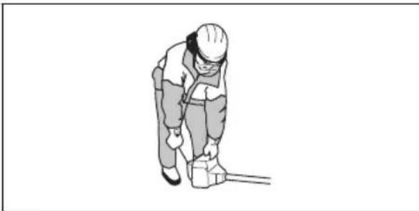
To use the product
- Hold the product as close to your body as possible to get the best balance. Use the harness to support the weight of the machine and make it easier to handle.
• Make sure that the tip does not touch the ground. - Do not rush the work, but work steadily until all the branches have been cut back cleanly.
• Always slow the engine to idle speed after each working operation. Long periods at full throttle without any load on the engine can lead to serious engine damage.
• Always work at full throttle. - Whenever possible position yourself so that you can make the cut at right angles to the branch.

natural_image
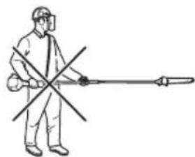
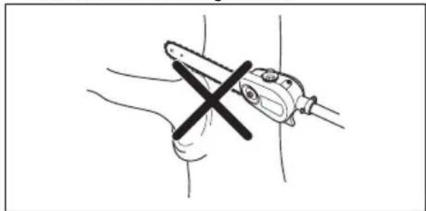
Diagram of a manual chain saw cutting a cylindrical part with a 90-degree angle indicator (no text or symbols present)- Do not work with the shaft held straight out in front of you as this increases the apparent weight of the cutting attachment.
natural_image
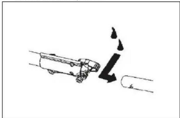
Person in full protective gear spraying a tool with a cross mark (no text or symbols visible)- Cut large branches in sections so that you have better control over where they fall.
natural_image
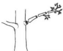
Simple line drawing of a plant stem with leaves, no text or symbols present- Never cut through the swelling at the root of the branch as this will slow down healing and increase the risk of fungal attack.
natural_image
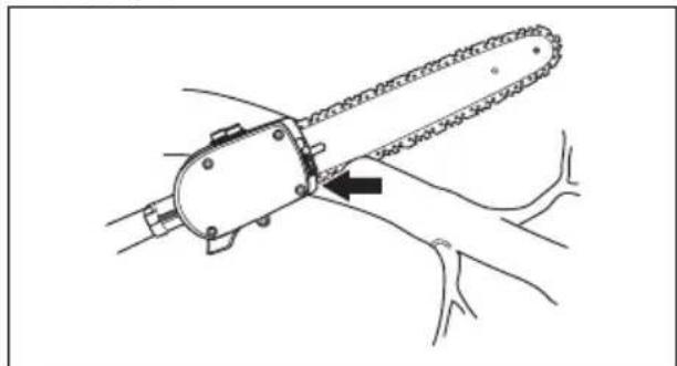
Illustration of a hand holding a tool with a cross mark, no text or symbols present- Use the stop at the base of the cutting head to provide support during cutting. This will help prevent the cutting attachment from bouncing on the branch.
natural_image
Line drawing of a chain saw cutting through a tool, showing mechanical components and a black arrow indicating the cutting direction (no text or symbols present)- Make an initial cut on the underside of the branch before cutting through the branch. This will prevent tearing of the bark, which could lead to slow healing and cause permanent damage to the tree. The cut should not be deeper than 13 of the branch thickness to prevent jamming. Keep the chain running while you withdraw the cutting attachment from the branch to prevent it jamming.

natural_image
Line drawing of a medical or surgical tool with an arrow pointing to a specific instrument (no text or symbols present)To start a cold engine
- Push the air purge bulb 10 times.
natural_image
Technical line drawing of an electric motor (no text or symbols present)- Move choke control to the full choke position.
- Hold the body of the product on the ground with your left hand. Do not step on the product. Pull the starter rope handle slowly until you feel some resistance.
natural_image
Illustration of a person in safety gear using a tool (no text or symbols)Note: Do not pull the throttle trigger while you start the engine.
- Pull the starter rope handle 3 times with force.

CAUTION: Do not pull the starter rope until it stops. Do not let go of the starter rope when it is fully extended. Release the starter rope slowly. Failure to obey these instructions can cause damage to the engine.
- Move the choke control to the half choke position.
- Pull the starter rope handle until the engine starts.
- Let the engine run for 10 seconds.
- Move the choke control to the no choke position.
To start a warm engine
- Slowly push the air purge bulb 10 times.
- Move the choke lever to the HALF CHOKE position.
- Pull the starter rope handle quickly until the engine runs.
- Move the choke lever to the NO CHOKE position.
To start the engine when the fuel is too hot
If the product does not start, the fuel can be too hot.
Note: Always use new fuel and decrease the operation time during warm weather.
- Put the product in a cool area away from open sunlight.
- Let the product cool down for 20 minutes at minimum.
- Press the air purge bulb again and again for 10-15 seconds.
- Obey the procedure to start a cold engine. Refer to To start a cold engine on page 14.
To stop the product
- Push the stop switch to stop the engine.
natural_image
Line drawing of a mechanical tool with a handle and lever mechanism (no text or symbols)Note: The stop switch automatically goes back to its initial position.
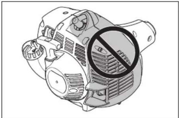
About the surface

WARNING: Do not put parts of your body in the grey marked area. If you touch the grey marked area it can result in burns to the skin. It can also cause electrical shock if the spark plug cap has been damaged. Do not use a product with a damaged spark plug cap.
natural_image
Illustration of an electric motor with a circular no-smoking symbol (no text or labels)Maintenance
Introduction
Below you will find some general maintenance instructions. If you need further information please contact your service workshop.
Maintenance schedule
The following is a list of the maintenance steps that must be performed on the product. Most of the items are described later in this chapter.
Note: The user must only carry out the maintenance and service work described in this operator's manual. More extensive work must be carried out by an authorized service workshop.
| Maintenance Daily Weekly Monthly | |||
| Clean the external surface. X | |||
| Examine the harness for damages. X | |||
| Do a check for damages on the suspension ring. X | |||
| Make sure that the throttle trigger lock and the throttle works correctly. X | |||
| Do a check of the stop switch to make sure that it works correctly. X | |||
| Make sure that the saw chain does not rotate at idle speed. X | |||
| Clean the air filter. Replace if necessary. X | |||
| Check the saw chain with regard to visible cracks in the rivets and links, whether the saw chain is stiff or whether the rivets and links are abnormally worn. | X | ||
| Clean the area under the protective cover. X | |||
| Make sure that the screws and nuts are tight. X | |||
| Examine the engine, the fuel tank and the fuel lines for leaks. X | |||
| Clean the cooling system. X | |||
| Examine the starter and the starter rope for damages. X | |||
| Clean the outside of the spark plug. Remove it and do a check of the electrode gap. Adjust the gap to the correct distance (refer to Technical data on page 23) or replace the spark plug. Make sure that the spark plug is fitted with a suppressor. | X | ||
| Clean the outside of the carburetor and the space around it. X | |||
| File off any burrs from the edges of the bar. X | |||
| Clean or replace the spark arrestor screen on the muffler. X | |||
| Clean the fuel tank. X | |||
| Do a check of the fuel filter for contamination and the fuel hose for cracks or other defects. Replace if necessary. | X | ||
| Do a check of all cables and connections. X | |||
| Do a check of the clutch, clutch springs and the clutch drum for wear. Replace if necessary by an authorized service workshop. | X | ||
| Examine the spark plug. Replace the spark plug if it is necessary. X |
To adjust the chain tension

WARNING: Put on the gloves before you adjust the chain tension. The chain is sharp and can cause injuries to you.
Note: The chain extends during the operation, specially when you operate for the first 15 minutes. You must examine and adjust the chain tension frequently after you use or refuel the product.
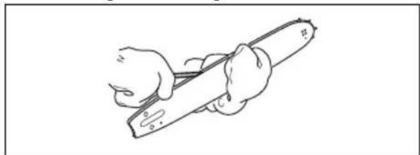
- Hold the lower end of the chain with a support.
-
Make sure that there are no kinks on the guide bar.
-
Loosen the bar nut (A), and then tighten it with your fingers.

natural_image
Diagram of a chain-linking tool labeled A and B, showing blade structure without any text or symbols beyond labels- Move the adjustment screw (B) clockwise until the chain touches the bottom of the guide bar rail. And move the adjustment screw clockwise 1/4 turn.
- Move the chain around the guide bar to make sure that all drive links stay in the bar groove.
- Lift the top of the guide bar, and tighten the bar nut with the bar tool.
-
Make sure that you can move the chain around the guide bar with the screwdriver end of the bar tool.
-
Loosen the bar nut lightly, and loosen the adjustment screw counterclockwise 1/4 turn if you cannot move the chain. Tighten the bar nut.
- Tighten the adjustment screw clockwise 1/4 turn if the chain stays loose and hangs below the guide bar.
To replace the chain

WARNING: When the chain becomes worn or damaged, replace it with the low kickback chain.
- Disconnect the spark plug.
- Remove the bar nuts and the clutch cover.
- Turn the adjustment screw counterclockwise by hand until the adjustment pin is located between the two indicator marks on the clutch cover.
-
Move the guide bar behind the sprocket until the guide bar stops against the sprocket. Remove the chain.
-
Hold the new chain with the drive links.

- Put the new chain above and behind the clutch drum. Set the drive links in the clutch drum sprocket.
- Keep the bottom of the drive links between the teeth of the sprocket in the nose of the guide bar.
- Set the drive links into the bar groove.
- Pull the guide bar forward until the new chain sets in the bar groove.
- Install the clutch cover.
- Set the adjustment pin in the lower hole of the guide bar.
- Install the bar nuts and tighten them with your hand.
- Adjust the chain tension To adjust the chain tension on page 16 and tighten fully the bar nuts.
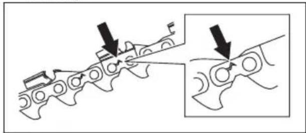
To examine the cutting equipment
- Make sure that there are no cracks in rivets and links and that no rivets are loose. Replace if it is necessary.
natural_image
Mechanical assembly diagram showing two stages of a chain with arrows indicating motion (no text or symbols)- Make sure that the saw chain is easy to bend. Replace the saw chain if it is rigid.
- Compare the saw chain with a new saw chain to examine if the rivets and links are worn.
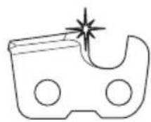
- Replace the saw chain when the longest part of the cutting tooth is less than 4 mm/0.16 in. Also replace the saw chain if there are cracks on the cutters.
natural_image
Pure technical line drawing of a mechanical part with no text or symbolsTo sharpen the saw chain
Information about the guide bar and saw chain

WARNING: Use protective gloves when you use or do maintenance on the saw chain. A saw chain that does not move can also cause injuries.
Replace a worn or damaged guide bar or saw chain with the guide bar and saw chain combination recommended by Husqvarna. This is necessary to keep the safety functions of the product. Refer to Accessories on page 23, for a list of replacement bar and chain combinations that we recommend.
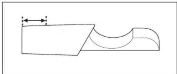
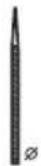
- Guide bar length, in/cm. Information about the guide bar length can usually be found on the rear end of the guide bar.
natural_image
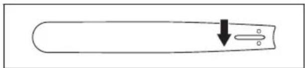
Simple line drawing of a test tube with a downward arrow pointing to a small oval object (no text or symbols)• Number of teeth on bar tip sprocket (T).

natural_image
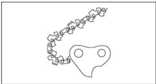
Simple line drawing of a chain with a star-like pattern inside, no text or symbols present.- Chain pitch, in. The distance between the drive links of the saw chain must align with the distance of the teeth on the bar tip sprocket and drive sprocket.

• Number of drive links. The number of drive links is decided by the type of guide bar.
natural_image
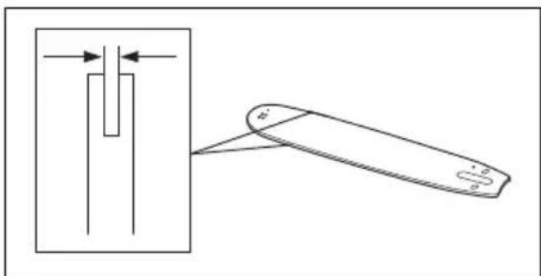
Pure mechanical linkage diagram without any text, numbers, or symbols- Bar groove width, in/mm. The groove width in guide bar must be the same as the chain drive links width.
natural_image
Diagram showing a mechanical component with arrows indicating direction, alongside a separate view of a folded or folded part (no text or symbols present)- Chain oil hole and hole for chain tensioner. The guide bar must align with product.
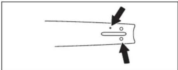
natural_image
Simple line drawing of a mechanical component with two arrows indicating direction (no text or symbols)- Drive link width, mm/in.
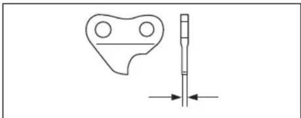
natural_image
Technical line drawing of a mechanical part with a cylindrical shaft and circular features, no text or symbols presentGeneral information about how to sharpen the cutters
Do not use a blunt saw chain. If the saw chain is blunt, you must apply more pressure to push the
guide bar through the wood. If the saw chain is very blunt, there will be no wood chips but sawdust.
A sharp saw chain eats through the wood and the wood chips becomes long and thick.
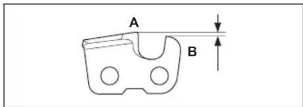
The cutting tooth (A) and the depth gauge (B) together makes the cutting part of the saw chain, the cutter. The difference in height between the two gives the cutting depth (depth gauge setting).
When you sharpen the cutter, think about the following:
- Filing angle.
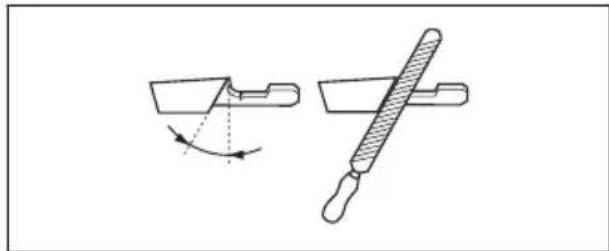
natural_image
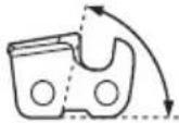
Technical line drawing of a mechanical tool with two views: one showing a curved arrow indicating rotation, the other showing a diagonal bar with handle (no text or symbols)- Cutting angle.
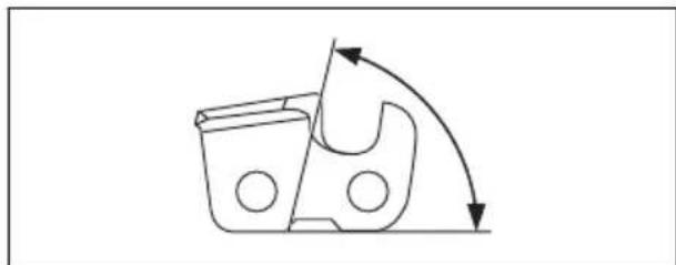
natural_image
Diagram of a mechanical component with curved arrows indicating motion or force direction (no text or symbols)- File position.

natural_image
Simple line drawing of a tool with a handle and lever, no text or symbols present- Round file diameter.

natural_image
Simple line drawing of a dropper with a small symbol (no text or labels)It is not easy to sharpen a saw chain correctly without the correct equipment. Use Husqvarna file gauge. This will help you to keep maximum cutting performance.
Note: Refer to To sharpen the cutters on page 19 for information about sharpening of the saw chain.
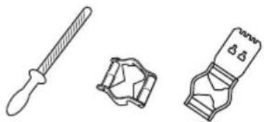
To sharpen the cutters
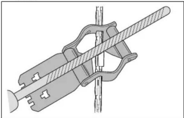
- Use a round file and a file gauge to sharpen the cutting teeth.
natural_image
Three technical illustrations of mechanical components: a dropper, a gear-like component, and a digital device (no text or symbols)Note: Refer to Filing equipment and filing angles on page 24 for information about which file and gauge that Husqvarna recommends for your saw chain.
- Apply the file gauge correctly on to the cutter. Refer to the instruction supplied with the file gauge.
- Move the file from the inner side of the cutting teeth and out. Decrease the pressure on the pull stroke.
natural_image
Mechanical assembly diagram showing a clamp or bracket with diagonal bracing and mounting base (no text or symbols)- Remove material from one side of all the cutting teeth.
- Turn the product around and remove material on the other side.
- Make sure that all cutting teeth are the same length.
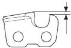
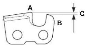
General information about how to adjust the depth gauge setting
The depth gauge setting (C) decreases when you sharpen the cutting tooth (A). To keep maximum cutting performance you must remove filing material from the depth gauge (B) to receive the recommended depth gauge setting. Refer to Technical data on page 23 for instructions about how to receive the correct depth gauge setting for your saw chain.
To adjust the depth gauge setting
Before you adjust the depth gauge setting or sharpen the cutters, refer to General information about how to sharpen the cutters on page 18, for instructions. We recommend you to adjust the depth gauge setting after each third operation that you sharpen the cutting teeth.
We recommend that you use our depth gauge tool to receive the correct depth gauge setting and bevel for the depth gauge.

natural_image
Two mechanical tools: a flat tool and a clamped device (no text or symbols visible)- Use a flat file and a depth gauge tool to adjust the depth gauge setting. Only use Husqvarna depth gauge tool to get the correct depth gauge setting and bevel for the depth gauge.
- Put the depth gauge tool on the saw chain.
Note: See the package of the depth gauge tool for more information about how to use the tool.
- Use the flat file to remove the part of the depth gauge that extends through the depth gauge tool.
natural_image
Pure mechanical diagram showing a tool interacting with a gear (no text or symbols)To do a check of the guide bar
- Make sure that the oil channel is not blocked. Clean if it is necessary.
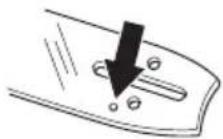
- Examine if there are burrs on the edges of the guide bar. Remove the burrs using a file.

natural_image
Diagram showing a tool interacting with a vertical bar and a cutting tool, with no visible text or symbols.
- Clean the groove in the guide bar.
natural_image
Line drawing of a hand holding a ruler or measuring tool (no text or symbols present)- Examine the groove in the guide bar for wear. Replace the guide bar if it is necessary.

- Examine if the guide bar tip is rough or very worn.

natural_image
Simple line drawing of a test tube with two crossed arrows indicating direction (no text or symbols)- Make sure that the bar tip sprocket turns freely and that the lubricating hole in the bar tip sprocket is not blocked. Clean and lubricate if it is necessary.

natural_image
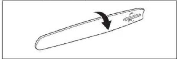
Illustration of a hand holding a pen with a circular arrow indicating rotation (no text or symbols)- Turn the guide bar daily to extend its life cycle.
natural_image
Simple line drawing of a tool with an arrow indicating rotation (no text or symbols)To check the chain lubrication
- Check the chain lubrication each time you refuel. Aim the tip of the bar at a light coloured surface about 20 cm (8 inches) away. After 1 minute running at 75 % throttle you should see a distinct line of oil on the light surface.

natural_image
Line drawing of a manual tool cutting a tree trunk, no text or symbols present- If the saw chain lubrication does not operate correctly, do a check of the guide bar. Refer to To do a check of the guide bar on page 19 for instructions. Speak to your servicing dealer if the maintenance steps does not help.
Air filter
Remove dust and dirt from the air filter to keep it clean and prevent these problems:
• Carburetor malfunctions.
- Problems when you start the product.
- Loss of engine power.
- Increased wear to engine parts.
• Too much fuel consumption.
To clean the air filter
- Remove the air filter cover and remove the filter.
- Hit the filter against a flat surface to make the particles fall off.

CAUTION: Do not use solvent or compressed air to clean the air filter.
- Put the air filter back. Make sure that the air filter fully seals against the air filter holder.
- Put the air filter cover back.
Note: An air filter that is used for a long time cannot be fully cleaned. Replace the air filter at regular intervals. Always replace a damaged air filter.
To do a check of the spark plug

CAUTION: Use the recommended spark plug. Refer to Technical data on page 23. An incorrect spark plug can cause damage to the product.
- If the product is not easy to start or to operate or if the product operates incorrectly at idle speed, examine the spark plug for unwanted materials. To decrease the risk of unwanted material on the spark plug electrodes, do these steps:
a) make sure that the idle speed is correctly adjusted.
b) make sure that the fuel mixture is correct.
c) make sure that the air filter is clean.
- Clean the spark plug if it is dirty.
- Make sure that the electrode gap is correct. Refer to, Technical data on page 23.
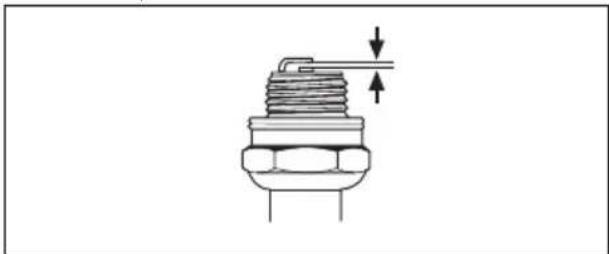
natural_image
Technical line drawing of a mechanical component with threaded body and shaft (no text or symbols)- Replace the spark plug monthly or more frequently if necessary.
To clean the cooling system

CAUTION: A dirty or blocked cooling system can make the product too hot, which can cause damage to the product.
The parts of the cooling system are the air intake on the starter (A), the cooling fins on the cylinder (B) and the cylinder cover (C).
- Clean the cooling system with a brush weekly or more frequently if it is necessary.

- Make sure that the cooling system is not dirty or blocked.
To adjust the idle speed
Your Husqvarna product is made to specifications that decrease harmful emissions.
- Make sure that the air filter is clean and that the air filter cover is attached to the product.
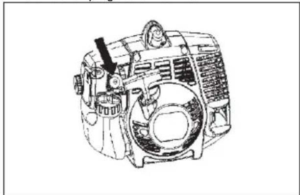
- Turn the idle speed screw (T) clockwise until the cutting attachment starts to turn.

natural_image
Technical line drawing of a mechanical assembly with a tool and arrow indicating a specific component (no text or symbols present)- Turn the idle speed screw (T) counterclockwise until the cutting attachment stops.
The idle speed is correct when the engine operates smoothly in all positions. The idle speed must be below the speed when the cutting attachment starts to turn.
Note: Refer to Technical data on page 23 for the recommended idle speed.

WARNING: If the cutting attachment does not stop when you adjust the idle speed, speak to your servicing dealer. Do not use the product until it is correctly adjusted or repaired.
To apply grease to the two-piece shaft
- Apply grease to the end of the drive shaft after each 30 hours of operation.
natural_image
Diagram of a truck with directional arrows indicating flow or movement (no text or symbols)Troubleshooting
The engine does not start
| Check Possible cause Procedure | ||
| Stop switch. The stop switch is in the stop position. | Let an approved service agent replace the stop switch. | |
| Fuel tank. Incorrect fuel type. Drain the fuel tank and fill with cor-rect fuel. | ||
| Spark plug and cylinder. The spark plug is dirty or wet. Make sure that the spark plug is dry and clean. | ||
The engine starts but stops again
| Check | Possible cause Procedure | |
| Fuel tank Incorrect fuel type. Empty | the fuel tank and fill it with | correct fuel. |
| Fuel filter The fuel filter is clogged. | Replace the fuel filter. | |
| Carburetor The idle speed is not correctly adjusted. | Adjust the idle speed with the idle speed screw T. | |
| Air filter The air filter is clogged. Clean the air filter. |
Transportation, storage and disposal
Transportation and storage
-
For storage and transportation of the product and fuel, make sure that there are no leaks or fumes. Sparks or open flames, for example from electrical devices or boilers, can start a fire.
• Always use approved containers for storage and transportation of fuel. -
Empty the fuel and chain oil tanks before transportation or before long-term storage. Discard the fuel and chain oil at an applicable disposal location.
-
Use the transportation guard on the product to prevent injuries or damage to the product. A saw chain that does not move can also cause serious injuries.
-
Remove the spark plug cap from the spark plug.
- Attach the product safely during transportation.
To prepare your product for long-term storage
- Stop the product and let it become cool before you disassemble it.
- Disassemble and clean the saw chain and the groove in the guide bar.

CAUTION: If the saw chain and guide bar are not cleaned, they can become rigid or blocked.
- Attach the transportation guard.
- Clean the product. Refer to Maintenance on page 15 for instructions.
- Do a complete servicing of the product.
Technical data
Technical data
| 128PS(LT28CSHV) | |
| Engine | |
| Cylinder displacement, cu.in / cm3 | 1.7 / 28 |
| Recommended max. speed, rpm 8000 | |
| Idle speed, rpm 2300-3200 | |
| Max. engine output, according to ISO 8893, kW / hp @ rpm 0.7 / 0.94 @ | 8500 |
| Catalytic converter muffler Yes | |
| Maximum output shaft rotation 7200 | |
| Ignition system | |
| Spark plug Champion RCJ 8Y | |
| Electrode gap, inch/mm 0.024 / 0.61 | |
| Fuel and lubrication system | |
| Fuel tank capacity, US Pint / litre 0.85 / 0.4 | |
| Oil tank capacity, US Pint / litre 0.3 / 0.14 | |
| Weight | |
| Without fuel, cutting attachment and guard, Lbs / kg 14.2 / 6.4 | |
Accessories
Guidebar and saw chain combinations
Recommended guide bar and saw chain combination.
| Guide bar Saw chain | ||||
| Length, in/cm Pitch, in Gauge, in/mm Type Length, drive links, no. | ||||
| 8/20 3/8 0.043/1.1 | Oregon 90P, 90PX | 34 | ||
| Poulan Pro UC 81 G, UC 81 GS | ||||
Filing equipment and filing angles
Using Husqvarna file gauge will give you the correct filing angles. We recommend you to always use a Husqvarna file gauge to restore the sharpness of the
saw chain. The part numbers are given in the table below.
If you do not know which saw chain you have on your product, turn to your servicing dealer.
 |  |  |  |  |  |  |
| Oregon 90P, 90PX | 11/64 in / 4.5 mm | 80° 30° | 0.025 in / 0.65 mm | US: 596 28 51-04CA: 505 69 81-03 | US: 596 28 47-01CA: 579 55 88-01 | |
| Poulan Pro UC 81 G, UC 81 GS |
Optional attachments
| Optional attachments Type Use with | ||
| Hedge trimmer attachment with shaft 952711674 128PS | ||
| Tree pruner attachment with shaft 952711672 128PS | ||
| Edger attachment with shaft 952711607 128PS | ||
| Cultivator attachment with shaft 952711608 128PS | ||
| Blower attachment with shaft 952711609 128PS | ||
| Brushcutter attachment with shaft 952711610 128PS |
Contenido
Introducción.... 25
Seguridad....28
Montaje.... 34
natural_image
Line drawing of a person in protective gear holding a long pole (no text or symbols)natural_image
Diagram of a mechanical lever mechanism with two arrows indicating motion direction (no text or symbols)natural_image
Diagram of a mechanical tool with a handle and lever mechanism, showing motion direction (no text or symbols)natural_image
Line drawing of a mechanical tool with a handle and lever, showing a small component inserted into the center (no text or symbols)natural_image
Technical line drawing of a mechanical device with a hand operating it, showing internal components and a separate fan-like structure (no text or symbols)natural_image
Technical line drawing of a mechanical component with mounting holes and connectors (no text or symbols)natural_image
Pure technical line drawing of a mechanical part with no text or symbolsnatural_image
Simple line drawing of a droplet falling into a container with two circular ports (no text or symbols)Montaje
natural_image
Technical line drawing of a mechanical clamp or bracket assembly (no text or symbols)natural_image
Diagram of a truck with an arrow indicating clockwise motion (no text or symbols)natural_image
Diagram of a truck on a road with an arrow indicating clockwise motion (no text or symbols)natural_image
Simple line drawing of a truck with an arrow indicating clockwise motion (no text or symbols)natural_image
Diagram showing a truck approaching a pipeline with two opposing arrows indicating direction (no text or symbols)natural_image
Simple line drawing of a car on a road with an arrow indicating clockwise motion (no text or symbols)natural_image
Illustration of a person in protective gear holding a long pole, with an inset showing hand positioning (no text or symbols)natural_image
Diagram of a car on a road with an arrow indicating clockwise motion (no text or symbols)natural_image
Diagram of a manual chain saw cutting through a cylindrical part, with a 90-degree angle indicator (no text or symbols present)natural_image
Line drawing of a person in full protective gear using a long-handled tool (no text or symbols)natural_image
Simple line drawing of a plant stem with a branch, no text or symbols presentnatural_image
Illustration of a hand holding a tool with a cross mark, no text or symbols presentnatural_image
Line drawing of a hand using a chain tag to cut a piece of material (no text or symbols present)natural_image
Line drawing of a hand holding a tool with an arrow indicating direction (no text or symbols)natural_image
Line drawing of an electric motor with visible blades and housing (no text or symbols)natural_image
Technical line drawing of a mechanical component with an arrow indicating direction (no text or symbols present)natural_image
Illustration of a person in safety gear handling equipment (no text or symbols visible)natural_image
Line drawing of a mechanical tool with a handle and lever, showing a small component inserted into a slot (no text or symbols)natural_image
Illustration of an electric motor with a prohibition symbol overlay (no text or symbols present)Mantenimiento
Introducción
natural_image
Diagram of a chain-linking device labeled A and B, showing blade structure without any text or symbols beyond labelsnatural_image
Mechanical assembly diagram showing two stages of a chain connection (no text or labels)natural_image
Pure technical line drawing of a mechanical part with no text or symbolsnatural_image
Simple line drawing of a test tube with a downward arrow indicating force or direction (no text or symbols)natural_image
Simple line drawing of a chain with a star-shaped internal structure (no text or symbols)natural_image
Diagram showing a mechanical component with arrows indicating direction, alongside a separate view of a tool or device (no text or symbols present)natural_image
Pure diagram of a mechanical or electrical component with two arrows indicating direction (no text or symbols)natural_image
Technical line drawing of a mechanical component with a shaft and circular features, no text or symbols presentnatural_image
Technical line drawing of a mechanical tool with two views: one showing a curved arrow indicating rotation, the other showing a diagonal bar with textured end (no text or symbols)- Ángulo del corte.

natural_image
Pure mechanical diagram showing a gear or cam mechanism with no text, numbers, or symbolsnatural_image
Line drawing of a tool with a handle and lever, no text or symbols presentnatural_image
Simple line drawing of a dropper with a small circular symbol (no text or labels)natural_image
Three technical line drawings of mechanical components: a dropper, a gear-like component, and a segmented device (no text or symbols)natural_image
Mechanical assembly diagram showing a clamp and rod mechanism (no text or symbols)natural_image
Two mechanical tools: a flat tool and a clamped device (no text or symbols visible)natural_image
Pure mechanical diagram showing a gear and shaft assembly without any text, numbers, or symbolsnatural_image
Line drawing of a hand using a tool to cut or spread a sheet of paper (no text or symbols present)natural_image
Simple line drawing of a tool with two crossed X marks and downward arrows (no text or symbols)natural_image
Illustration of a hand holding a wrist with a curved arrow indicating rotation (no text or symbols)natural_image
Simple line drawing of a tool or blade with an arrow indicating direction (no text or symbols)natural_image
Line drawing of a tool interacting with a branch (no text or symbols)natural_image
Technical line drawing of a mechanical assembly with a tool and arrow indicating motion (no text or symbols)natural_image
Diagram showing a truck approaching a road with directional arrows indicating motion (no text or symbols)natural_image
Line drawing of a person in protective gear holding a long pole (no text or symbols)natural_image
Diagram of a tool handle with arrows indicating movement or force (no text or symbols)natural_image
Diagram of a mechanical tool with a handle and lever mechanism, showing a force or motion indicator (no text or symbols present)natural_image
Line drawing of a mechanical clamp or lever mechanism with a downward arrow indicating force or movement (no text or symbols present)natural_image
Technical line drawing of a mechanical device with a hand operating it, showing internal components and a separate fan-like structure (no text or symbols)natural_image
Technical line drawing of a mechanical component with mounting holes and connectors (no text or symbols)natural_image
Pure technical diagram of a mechanical component with no text or symbolsnatural_image
Simple line drawing of a droplet falling from a container with a handle, no text or symbols present.Montage
natural_image
Technical line drawing of a mechanical clamp or bracket assembly with mounting base (no text or symbols)natural_image
Diagram of a car with an arrow indicating clockwise motion (no text or symbols)natural_image
Simple line drawing of a car on a road with an arrow indicating clockwise motion (no text or symbols)natural_image
Diagram of a truck with an arrow indicating clockwise motion (no text or symbols)natural_image
Diagram of a tanker truck moving with two opposing arrows indicating speed or flow (no text or symbols)natural_image
Diagram of a car on a road with an arrow indicating clockwise motion (no text or symbols)natural_image
Illustration of a person in protective gear using a long-handled tool, with an inset showing hand positioning (no text or symbols)natural_image
Diagram of a car on a road with an arrow indicating clockwise motion (no text or symbols)natural_image
Technical illustration of a chain saw cutting a cylindrical part with a 90-degree angle indicator (no text or symbols present)natural_image
Line drawing of a person in full protective gear using a long-handled tool (no text or symbols)natural_image
Simple line drawing of a hand holding a branch with a leafy branch extending upward (no text or symbols)natural_image
Illustration of a hand holding a medical device with a cross mark, no text or symbols presentnatural_image
Line drawing of a chain-linking tool being cut with a black arrow indicating the blade (no text or symbols present)natural_image
Line drawing of a hand holding a medical or surgical tool, with an arrow pointing to the tool (no text or symbols present)natural_image
Technical line drawing of an electric motor (no text or symbols present)natural_image
Illustration of a person in safety gear handling equipment (no text or symbols)natural_image
Line drawing of a mechanical tool with a handle and screw base (no text or symbols)natural_image
Illustration of an electric motor with a prohibition symbol overlay (no text or symbols present)Entretien
Introduction
natural_image
Diagram of a chain-linking tool labeled A and B, showing blade structure without any text or symbols beyond labelsnatural_image
Mechanical assembly diagram showing two stages of a tool or component with arrows indicating movement (no text or symbols present)natural_image
Pure technical line drawing of a mechanical part with no text or symbolsAffûter la chaîne.
natural_image
Simple line drawing of a test tube with a downward arrow indicating compression or dislocation (no text or symbols)natural_image
Simple line drawing of a chain with a star-shaped object inside (no text or symbols)natural_image
Diagram showing a vertical tube being inserted into a rectangular block, with an arrow indicating direction (no text or symbols present)natural_image
Simple line drawing of a mechanical component with two arrows indicating direction (no text or symbols)natural_image
Technical line drawing of a mechanical part with a cylindrical shaft and circular features, showing dimension arrows (no text or symbols)natural_image
Technical line drawing of a mechanical tool with a curved arrow indicating rotation (no text or symbols)• L'angle de coupe.
natural_image
Pure mechanical diagram showing a gear or cam mechanism with curved arrows indicating motion (no text or symbols)• La position de la lime.

natural_image
Line drawing of a screwdriver holding a tool, no text or symbols presentnatural_image
Simple line drawing of a dropper with a small symbol (no text or labels)natural_image
Three technical illustrations of mechanical components: a dropper, a gear-like component, and a connector (no text or symbols)natural_image
Mechanical assembly diagram showing a tool interacting with a bracket and rod (no text or symbols)natural_image
Two mechanical tools: a tool with a handle and a clamped device (no text or symbols visible)natural_image
Pure mechanical diagram showing a tool interacting with a gear (no text or symbols)
natural_image
Pure mechanical diagram showing a tool interacting with a gear or screwdriver (no text or symbols)natural_image
Illustration of a pair of tools with a magnified inset showing a cylindrical object (no text or symbols)natural_image
Line drawing of a hand using a tool to cut a cylindrical object (no text or symbols)natural_image
Simple line drawing of a pen with two crossed lines and arrows indicating direction (no text or symbols)natural_image
Illustration of a hand holding a device with a curved arrow indicating rotation (no text or symbols)natural_image
Simple line drawing of a tool with an arrow indicating direction (no text or symbols)natural_image
Line drawing of a tool cutting through tree branches (no text or symbols)natural_image
Technical line drawing of a mechanical component with no visible text or symbolsnatural_image
Technical line drawing of a mechanical component with a tool inserted, showing no text or symbols.natural_image
Diagram of a tanker truck with directional arrows indicating flow or movement (no text or symbols)Dépannage
Original instructions


- Introduction
- Intended use
- Product overview
- Symbols on the product
- WARNING!
- Product liability
- Safety
- Safety definitions
- General safety instructions
- Safety instructions for assembly
- Safety instructions for operation
- Personal protective equipment
- WARNING: Read the warning instructions that follow before you use the product.
- Safety devices on the product
- To do a check of the throttle trigger lockout
- To do a check of the stop switch
- Fuel safety
- Safety instructions for maintenance
- Safety instructions for the cutting equipment
- Assembly
- To attach the loop handle
- To assemble the two-piece shaft
- To attach the pole saw attachment
- To adjust the harness
- To disassemble the two-piece shaft
- Operation
- To check before starting
- Fuel
- Premixed fuel
- To mix fuel
- Gasoline
- Two-stroke oil
- To fill the fuel tank
- To do a run-in
- To use the correct chain oil
- To use the product
- To start a cold engine
- To start a warm engine
- To start the engine when the fuel is too hot
- To stop the product
- About the surface
- Maintenance
- Maintenance schedule
- To adjust the chain tension
- To replace the chain
- To examine the cutting equipment
- To sharpen the saw chain
- General information about how to sharpen the cutters
- To sharpen the cutters
- General information about how to adjust the depth gauge setting
- To adjust the depth gauge setting
- To do a check of the guide bar
- To check the chain lubrication
- Air filter
- To clean the air filter
- To do a check of the spark plug
- To clean the cooling system
- To adjust the idle speed
- To apply grease to the two-piece shaft
- Troubleshooting
- Transportation, storage and disposal
- Transportation and storage
- To prepare your product for long-term storage
- Technical data
- Accessories
- Guidebar and saw chain combinations
- Filing equipment and filing angles
- Contenido
- Montaje
- Mantenimiento
- Introducción
- Montage
- Entretien
- Affûter la chaîne.
- Dépannage
Brand : HUSQVARNA
Model : 128PS
Category : Saw