
Peak Power Pack - Battery VICTRON ENERGY - Free user manual and instructions
Find the device manual for free Peak Power Pack VICTRON ENERGY in PDF.

| Product type | Lithium-ion battery with built-in charger |
| Brand | Victron Energy |
| Model | Peak Power Pack (PPP-20, PPP-30, PPP-40) |
| Capacity | 20 Ah / 30 Ah / 40 Ah depending on model |
| Stored energy | 256 Wh / 384 Wh / 512 Wh |
| Nominal voltage | 12.8 V DC |
| Battery type | Lithium-ion (LiFePO4) |
| Dimensions (h x w x d) | 132 x 190 x 172 mm (PPP-20), 172 x 190 x 172 mm (PPP-30), 212 x 190 x 172 mm (PPP-40) |
| Weight | 3.8 kg (PPP-20), 5.4 kg (PPP-30), 8.6 kg (PPP-40) |
| Output 1 (high power) | 150 A continuous, 200 A max 10 s, short-circuit threshold 300 A |
| Output 2 (auxiliary) | 30 A continuous, 50 A max 10 s, short-circuit threshold 80 A |
| Input 1 (solar/vehicle) | 11 V to 25 V DC, max current 7 A |
| Input 2 (mains adapter) | 15 V DC, 3 A, included adapter 100-240 VAC |
| Protections | Overload, short-circuit, overheating, excessive discharge |
| Communication | VE.Direct port for USB cable or Bluetooth Smart dongle (optional) |
| Operating temperature | Charge: 0 °C to 40 °C; Discharge: -20 °C to +40 °C; Storage: -20 °C to +40 °C |
| Self-discharge (on) | Less than 13 Ah/year (<1.4 mA) |
| Self-discharge (storage mode) | Less than 6.5 Ah/year (<0.7 mA) |
| Safety standards | EN/IEC 60335-1, EN/IEC 60335-2-29, EN/IEC 62109 |
| EMC standards | EN 55014-1, EN 55014-2, IEC 61000-3-2, IEC 61000-3-3, EN 50498 |
| Status indicator | Multifunction push button with bicolor LED indicator (blue/red) |
Frequently Asked Questions - Peak Power Pack VICTRON ENERGY
User questions about Peak Power Pack VICTRON ENERGY
0 question about this device. Answer the ones you know or ask your own.
Ask a new question about this device
Download the instructions for your Battery in PDF format for free! Find your manual Peak Power Pack - VICTRON ENERGY and take your electronic device back in hand. On this page are published all the documents necessary for the use of your device. Peak Power Pack by VICTRON ENERGY.
USER MANUAL Peak Power Pack VICTRON ENERGY
natural_image
Abstract blue wave-like pattern with no text or symbolsvictron energy
BLUE POWER
Manual
三
Handleiding
Z
Manuel
π
Anleitung
DE
Manual
m
Användarhandbok
s m
1. General Description
A Li-ion battery pack with intrinsically safe LiFePO4 cells, a built-in charger and outstanding peak output power performance.
Nominal voltage: 12,8 V
Battery capacity range: 20 Ah to 40 Ah
Low weight and easy to install
- Ideally suited for mobile applications
Thoroughly protected against misuse
- Excellent performance in solar and other applications where frequent deep discharge and insufficient recharge would quickly damage lead-acid batteries
Output 1: high current output for caravan movers and other high power applications
- Caravan mover application: automatic shutdown of the high power output 30 minutes after enabling
- Other applications: The high power output can be switched to "always on" mode
- Short circuit proof
- With battery over discharge protection
Output 2: auxiliary output for low power DC loads
- Always on
- Short circuit proof
- With battery over discharge protection
Input 1: multi-purpose vehicle battery/solar charger input
- Voltage and current regulated to safely charge the Li-ion battery. Virtually any source of DC electric power can be connected to this input, as long as 11 V < Vin < 25 V
Input 2: second input to connect a 15 V DC power supply
- A 3 A power supply is included (connects to 100/240 VAC mains)
Fast charging possible through input 1 (high current output)
- A battery charger or inverter/charger can be connected to the high power output for fast charging. The maximum charge current is 40 A and the absolute maximum voltage is 14 V (a higher charge voltage may damage the Li-ion cells in case of cell charge unbalance).
Storage mode
- Reduces battery current drain to virtually zero. Prevents damage due to battery over discharge during long term storage.
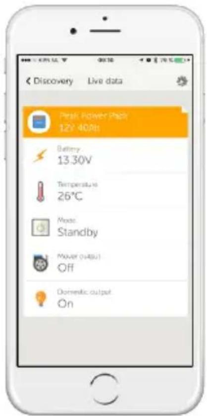
Real-time data display on Apple and Android smartphones, tablets and other devices
VE.Direct Bluetooth Smart dongle needed: see our website.
2. Safety instructions

Danger of explosion from sparking
- Please read this manual carefully before the product is installed and put into use.
- This product is designed and tested in accordance with international standards. The equipment should be used for the designated application only.
• Install the product in a heatproof environment. Ensure therefore that there are no chemicals, plastic parts, curtains or other textiles, etc. in the immediate vicinity of the equipment. - Do not connect in series to get a higher voltage. (The overload and short circuit protections might fail.)
- Ensure that the equipment is used under the correct operating conditions. Never operate it in a wet environment.
- Never use the product at sites where gas or dust explosions could occur.
- Ensure that there is always sufficient free space around the product for ventilation.
- Connections must always be made in the sequence described in section 3.5.
- Use flexible multistranded copper cable for the output 1 and output 2 connections.
The maximum diameter of the individual strands is 0,4 mm /0,125 mm 2 (0.016 inch/AWG26).
A 25 mm 2 cable, for example, should have at least 196 strands (class 5 or higher stranding according to VDE 0295, IEC 60228 and BS6360). Also known as H07V-K cable.
An AWG2 gauge cable should have at least 259/26 stranding (259 strands of AWG26).
In case of thicker strands the contact area will be too small and the resulting high contact resistance will cause severe overheating, eventually resulting in fire.

natural_image
Two rolled cigarettes with a red X symbol on the side (no text or symbols present)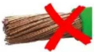
natural_image
Close-up of bundled brown material with a red X symbol overlay (no text or symbols on the material itself)
natural_image
Close-up of a wooden log with a green checkmark overlay (no text or symbols)3. Battery care
- The PPP must be fully charged before first use. A full charge is indicated by the blue LED lighting continuously
- When not in use, the PPP must be switched to storage mode and fully charged at least every 12 months
- In case of seasonal use the PPP must be at least 50 % charged before storing. Pressing the button for 5s will put the PPP in storage mode, acknowledged by flashing blue.
4. Installation
When placing the Peak Power Pack it should be observed that it has sufficient ventilation all around. A space of at least 5 cm must be allowed.
In case of high temperature, the product will switch off, and an error is indicated by the LED flashing red.
The Peak Power Pack leaves the factory in storage mode to protect it from deep discharge. Prior to first use, the button must be pressed for 5s. The PPP is now ready for use, confirmed by the LED flashing blue.
Installing the PPP in a caravan
The enclosure is made of plastic and must be mounted on the caravan floor inside a cabinet or storage area using the included strap or a suitable battery clamp.
After mounting the PPP on the caravan floor, drill an 8 mm hole in the cabinet wall for the remote button/LED. The button/LED should be mounted in an area that is easily accessible to press the button and viewing the LED. Pass the 3.5 mm jack plug and the cable through the hole from the outside until the button locks in place. The 3.5 mm jack can now be connected to the remote button socket of the PPP.
Connection of the high current output to a caravan mover
The mover control box can be connected directly to the “mover” output of the PPP. The cable ends must be stripped for 15 mm. Carefully insert all wire strands into the connectors and tighten the screws. The recommended tightening torque is 2 Nm. Be careful to insert the wire end completely into the terminal without clamping the plastic wire insulation, and without leaving strands out.
Use the cables supplied with the caravan mover kit, or as recommended by the mover manufacturer. Cable cross sections of 10 mm2 to 16 mm2 are commonly used.
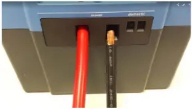
Because of the high currents involved when operating the mover, a careful installation of the cables is crucial. Improper connections of the cables can cause loss of performance, overheating and damage. The Victron PPP is equipped with high-power terminals that can provide a reliable connection on fine stranded wire ends. High quality eyelets and specialist crimping tools are therefore not needed. Solid wire or wires with thick strands will not provide a proper connection.
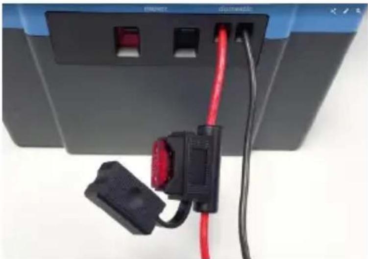
Connection of the domestic output
A low power household load, such as LED lights, low power water pump or a 12V-LCD TV can be powered from the “domestic” output. A properly sized in-line fuse must be connected within 10 cm of the positive battery terminal. This is to prevent overheating/melting of the cables.
A 1,5 mm 2 cable should have a fuse of up to 10 A
A 2,5 mm 4 cable must be fused at maximum 16 A.
natural_image
Close-up of a device's cable and socket connected to a terminal block, showing red and black wires (no text or symbols visible)Connection of the power adapter (mains)
The “mains” jack connects to the 15 V power adapter (included). The power adapter has to be connected to a mains outlet socket. (100...240 VAC, 50...60 Hz)
The car/solar input
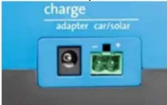
A 11 to 25 VDC power source can be connected to the car/solar input, to charge the PPP from the towing car electrical circuit, a 12V-solar panel or a 12V-battery. When connecting to a car trailer plug, the used contact must be carefully selected, not to overload any circuit or to over discharge the car battery.
As an example, the commonly used 13p “Jaeger” plug is described. The pin numbering for the “Multicon WeST” plug is the same.

| Pin | DIN | Name | Color | Cable size | |
| mm2 | AWG | ||||
| 1 | L | Left Turn Signal | Yellow | 1.5 | 15 |
| 2 | Rear fog lamps | Blue | 1.5 | 15 | |
| 3 | 31 | Ground(-) for pin 1 - 8 | White | 2.5 | 13 |
| 4 | R | Right Turn Signal | Green | 1.5 | 15 |
| 5 | 58R | Tail, side, registration | Brown | 1.5 | 15 |
| 6 | 54 | Stop lamps | Red | 1.5 | 15 |
| 7 | 58L | Tail, side, registration | Black | 1.5 | 15 |
| 8 | Reversing lamps | Pink | 1.5 | 15 | |
| 9 | 30 | +12 V permanent | Orange | 2.5 | 13 |
| 10 | 15 | +12 V via ignition lock | Grey | 2.5 | 13 |
| 11 | 31 | Ground (-) for pin 10 | Black/White | 2.5 | 13 |
| 12 | Trailer present | Light Grey | 1.5 | 15 | |
| 13 | 31 | Ground (-) for pin 9 | Red/White | 2.5 | 13 |
Pins 9 or 10 with their respective Ground returns (11 or 13) can be used.
Normally, pins 9 and 10 are fused at 20 A in the car's fuse panel. The advantage of using pin 10 is that the PPP only charges when the ignition is on, so the car's battery doesn't drain when parking. Pin 10 is a non-standard option on most car models, so please verify it's available.
If connected to pin 9 be careful not to drain the car battery when the engine is not running. Disconnect the trailer plug on longer stops.
Most absorption type refrigerators use up to 10 A. When the PPP is added on the same circuit, the 20 A fuse is not overloaded but there is no available power for other loads. When other loads are used, such as the water pump or lamps, the refrigerator must be switched to gas power.
5. Operation
Push button:
- Press shortly: The high power output will be on during 30 min., LED lights red. The domestic output will be on permanently (domestic output not available on 8 Ah model).
- Press during 2s: Both the high power output and the domestic output will be permanently on. The red LED blinks slowly.
- Press during 5s: The PPP will switch off (= storage mode), LED blue, flashes 10 times. Both the high power output and the domestic output will be off. The adapter or car/solar input can still be used to charge the PPP.
LED status indication:
● = On
= Slow flash (2 seconds on, 2 seconds off)
◎ = Quick flash ( 12 second on, 12 second off)
| Red LED Blue LED | ||
| Peak Power Pack Off | ||
| High Power output ON | ● | |
| High Power output permanently ON | ◎ | |
| Mover overload/short circuit/over temperature | ◎ | |
| Charge Car/Solar. | ◎ | |
| Peak Power Pack fully charged. | ● | |
| Storage mode | ◎ (during 10s) |
Operation of the mains charger is indicated by the green LED on the charger.
6. Solving problems
| Failure description | Possible Cause | Remedy |
| No power Battery | discharged | Charge |
| No power, LED flashing RED | Output shorted | Check wiring |
| No power, LED flashing RED | Over temperature | Cool down |
| Power output switches off repeatedly when driving with a mover | Overload Use | correct tire pressure and roller engagement force. Avoid digging of the nose wheel. Avoid kerbstones. Use a PPP properly sized for the caravan/mover. |
| Battery doesn’t charge due to freezing temperature | Move to an are | with temperature above 0 °C |
7. Maintenance
The Peak Power Pack is maintenance-free, but must be fully charged at least once per year, and after each use.
Important:
The PPP must be charged and switched off prior to a long storage period.
8. Peak Power Pack FAQ List
Subdivided into:
I. Charging
II. Maintenance
III. Use
IV. Technology
V. Installation/Connection
VI. Interesting facts
We obviously recommend the "future" Victron Energy Peak Power Pack user to carefully read the manual so as to make optimal use of the Victron Energy PPP. The following FAQ list is to be used as a supplement to the manual.
| Question | Answer | |
| I. CHARGING | ||
| 1 | How much does a PPP demand from the car's battery? | Max. 7 A, depending on the car's battery voltage. |
| 2 | How can the PPP be charged? | a. With the included 110...230 V charger (15 V, 3 A).b. With a solar panel connected to the car/solar input. The PPP will control the charge voltage and limit the input current to max. 7 A.The solar panel, therefore, may be overrated.c. From the car or any other 12 V power source. The PPP will control the charge voltage and current.d. The PPP can also be fast-charged by connecting a charger. A (max) charger to the high current output. Max charge voltage: 14,0 V. See datasheet for max. charge current. |
| 3 | Is the PPPalready fully charged at the time of purchase? | No, it is charged to 60%...80%. |
| 5 | How many Amperes are at least required in order to charge the PPP at the camping site? | Any 110...230 V camping site connection will do. |
| 6 | Can the PPP be charged both by means of a solar panel and a car charger simultaneously? | No.Simultaneous charging from mains and car or solar is possible. If you wish to connect the car charger and the solar panel simultaneously, a diode bridge is needed to avoid return current. |
| II. MAINTENANCE | ||
| 1 | What should I do when I store my caravan for the winter? | Fully charge before the winter storage. When the blue LED indicates the PPP is fully charged, press the button for 10s. Storage mode is entered and indicated by the LED flashing blue. |
| 2 | What is the service life? | Under normal use the expected service life is 7-10 years. |
| 3 | What happens in case of full discharge? | The PPP switches off automatically. |
| 4 | Is it harmful to always charge the PPP for just a short time? | No, the PPP has no memory effect. |
| 5 | What is the influence of temperature on lifetime and performance? | Storage: the colder, the longer the service life. Use: the performance is best around 25...35 degrees Celsius. Freezing temperatures adversely affect maximum current output of |
| any battery. | ||
| 6. | What if I accidentally drop the PPP? | No dangerous situation will occur, but correct operation can no longer be guaranteed. |
| 1 | Is it possible to start a car using the PPP? | No. |
| 2 | Does the PPP switch off automatically? | Yes, The mover output switches off after 20 min. Both outputs are switched off in case of undercharge. Normal operation can be resumed only after sufficient charging. |
| 3 | How long can I drive my Mover? | This depends on the type of mover, the weight of the caravan and the surface. As an average value you can assume: approx. 10 minutes for a caravan of 1600 kg on a relatively level surface. The larger versions give proportionally more driving time. |
| 4 | How do I know the PPP is fully charged? | The blue LED will light continuously. |
| 5 | Is the PPP also suitable for a double-axle trailer? | Yes. For heavier caravans a larger PPP is recommended. |
| Can the PPP be used as a power supply? | Yes. Using the “domestic” output, lights and water pumps can be supplied. | |
| 7. | Where can I take the PPP for disposal? | To a disposal station or the municipal waste collection point. |
| 8. | Does frequently stopping and starting the Mover affect the available usage time? | No. |
| 9. | Can the PPP be used incombination with a 12 V fully automatic satellite installation? | Yes. Use the “domestic” output to power the system. Disconnect thesystem after use to prevent unnecessary discharge. |
| 10. | Does the nose wheel weight have any importance? | Yes, the more weight on the shaft/nose wheel, the deeper it can dig into the ground. This will cause added load for the system leading to poor performance. |
| 11. | Is there any capacity loss over the years? | Yes. |
| 12. | Is it possible to connect the PPP both to 12 V and 230 V simultaneously? | Yes. |
| 13. | To what extent is it allowed to completely discharge the PPP? | This is allowed. Recharge immediately after use to prevent premature failure. |
| IV. TECHNOLOGY | ||
| 1. | Is the PPP protected against: a. Short circuit? b. Overload? | a. Yes.b. Yes, by means of electronic switches and an internal non-replaceable fuse. |
| 2. | Can the PPP catch fire in the event of a short circuit? | No. There is an electronic short-circuit and overload protection. The PPP contains LiFePO4 cells, which in case of short circuit do not catch fire as opposed to lithium manganese and lithium polymer cells used in laptops, mobile phones and model aero planes.Please ensure large diameter cables are used. If cables with insufficient cross section are |
| used, the current from the PPP may cause the wires to glow or catch fire. | ||
| 3. | Are there any similarities with mobile phone, laptop or bicycle batteries? | The lithium iron phosphate cells in the PPP have no "thermal run away" effect and will therefore not catch fire or explode in case of misuse. See also "Interesting facts". |
| 4. | Can the output of the PPP be connected in parallel to another power supply or battery? | No.Depending on the relative voltages |
| 5. | Is a booster needed to charge the PPP from the car's electrical circuit? | No. The integrated charger will operate correctly from approx. 11 V to 25 V input. The input current is limited electronically to approx. 7 A. |
| V. INSTALLATION/ CONNECTION | ||
| 1. | How to connect the PPP tot the car's electrical system for charging. | Connect the PPP to the trailer connector. It can be connected to the "permanent" (9) or "refrigerator/charge" (10) pin. Do not overload the circuit adding many loads. Using pin 9 may discharge the car's battery when parking. Please note that not all cars have a fully wired trailer connector, so pins may be missing. |
| 2. | Do I still need the main switch for my Mover? | No. The device switches on and off through electronic switches. If a main switch is already installed, it does not have to be removed. |
| 3. | How can the PPP be installed? | The PPP can be installed horizontally on the bottom of the caravan. |
| 4. | Is the length ofthe cables between the PPP and the Mover electronics important? | Yes. They need to be as short aspossible (max. 1 m); diameter between 10 and 16 mm2. A main power switch is allowed but not required. |
| 5. | My caravan is garaged and constantly connected to 230 V. Is this harmful or should the PPP be disconnected? | The mains adapter for the PPP can remain constantly connected to 230 V. |
| VI. INTERESTING FACTS | ||
| 1. | PPP ageing | As with all batteries the PPP (Li-ion battery) will lose some capacity as it ages. A high storage temperature will adversely affect the lifetime.1. The PPP contains lithium-iron-phosphate cells with a longer service life than the lithium manganese oxide cells as used in laptop computers.2. Lithium-iron-phosphate cells have no thermal run-away effect like lithium manganese oxide ion cells, avoiding the possibility of fire or explosions in case of short circuit, overload, perforation, overheating, etc. |
| Peak Power Pack | PPP-20 | PPP-30 | PPP-40 |
| Capacity | 20 Ah | 30 Ah | 40 Ah |
| Stored energy | 256 Wh | 384 Wh | 512 Wh |
| Battery type | Lithium-ion ( LiFePO4) | ||
| Nominal voltage | 12,8 V | ||
| No load battery drain when on | <13 Ah / year (< 1,4 mA) | ||
| Battery drain in storage mode | < 6,5 Ah / year (< 0,7 mA) | ||
Output 1: high current output
| Continuous output current 150 A | |||
| Maximum output current (10 s) | 200 A | ||
| Short circuit trip level 300 A | |||
| Protections | Overload / short circuit / over temperature / over discharge | ||
| Maximum input (charge) current | n.a. | 15 A (no protection) | 20 A (no protection) |
| Recommended charging voltage | 14 V (no protection) | ||
| Maximum input (charge) voltage | 14,2 V (no protection) | ||
| Maximum cable cross section 16 mm2 (screw terminals) | |||
Output 2: auxiliary output
| Continuous output current 30 A | ||
| Maximum output current (10 s) 50 A | ||
| Short circuit trip level 80 A | ||
| Protections | Overload/short circuit/over temperature/over discharge | |
| Maximum input (charge) current | n.a. | 10 A (no protection) |
| Recommended charging voltage | 14 V (no protection) | |
| Maximum input (charge) voltage | 14,2 V (no protection) | |
| Maximum cable cross section | 6 mm 2 (screw terminals) | |
Input 1: multi-purpose vehicle battery / solar charger input
| Input voltage range | 11 V < Vin < 25 V | |
| Input current limit | 7 A | |
| Input 2: power adapter | ||
| Adapter output voltage | 15 V | |
| Adapter output current | 3 A | |
| Adapter input voltage | 100/240 VAC | 50/60 Hz |
GENERAL
| Monitoring and control | Multi-functional push button with bi-colour LED | ||
| VE.Direct port | Connects to a computer (VE.Direct to USB cable needed) or a smart phone (VE.Direct Bluetooth Smart dongle needed) | ||
| Operating temperature range | Batt. charging: 0 °C to 40 °CBatt. discharging: -20 °C to +40 °CStorage: -20 °C to +40 °C(charging / discharging inhibited when outside specified temperature range) | ||
| Humidity (non condensing) | Max 95 % | ||
| Weight | 3,8 kg | 5,4 kg | 8,6 kg |
| Dimensions (h x w x d) in mm | 132 x 190 x 172 | 172 x 190 x 172 | 212 x 190 x 172 |
| Safety | EN/IEC 60335-1, EN/IEC 60335-2-29, EN/IEC 62109 |
| Emission, Immunity | EN 55014-1, EN 55014-2, IEC 61000-3-2, IEC 61000-3-3, EN 50498 |
natural_image
Three types of copper wire fibers: rolled paper, crossed with red X marks, and thick brown, with green checkmarks (no text or symbols)natural_image
Close-up of a device's cable connector with red cable inserted into a black socket (no text or symbols visible)natural_image
Close-up of a device's cable and plug assembly with red and black wires, no visible text or symbolsnatural_image
Illustration of rolled documents with a red X symbol overlay (no text or symbols on the documents)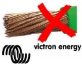

natural_image
Close-up of a wooden plank with a green downward arrow overlay (no text or symbols)natural_image
Close-up of a device's cable and connector with red and black wires, no visible text or symbols(100...240 VCA, 50...60 Hz)
natural_image
Two rolled papers with a red X symbol on the right, no text or symbols present
natural_image
Close-up of bundled brown cable with a red X symbol (no text or symbols on the cable itself)
natural_image
Close-up of a wooden plank with a green downward arrow overlay (no text or symbols)3. Batteriepflege
natural_image
Close-up of a device's cable inserted into a port, showing red cable and black connector (no text or symbols visible)natural_image
Close-up of a device's cable and plug assembly with red and black wires, no visible text or symbolsnatural_image
Illustration of rolled documents with a red X symbol (no text or symbols present)
natural_image
Stack of brown bundled cables with a red X symbol (no text or symbols on cables)
natural_image
Close-up of a wooden plank with a green checkmark overlay (no text or symbols)
victron energy
natural_image
Close-up of a device's cable inserted into a terminal block, showing red and orange wires (no text or symbols visible)natural_image
Close-up of a device's cable and connector with red and black wires, no visible text or symbolsnatural_image
Red X symbol overlaid on a stack of broken cylindrical objects (no text or symbols)
natural_image
Bulleted brown cable with a red X symbol, no text or symbols present
natural_image
Close-up of a wooden log with a green checkmark overlay (no text or symbols)3. Batteriskötsel
natural_image
Close-up of a device rear panel showing two black connectors with red wires connected to a blue interface (no visible text or symbols)Date : August 22 nd , 2022
Victron Energy B.V.
De Paal 35 | 1351 JG Almere
PO Box 50016 | 1305 AA Almere | The Netherlands
E-mail : sales@victronenergy.com
www.victronenergy.com


- victron energy
- BLUE POWER
- General Description
- Low weight and easy to install
- Thoroughly protected against misuse
- Output 1: high current output for caravan movers and other high power applications
- Output 2: auxiliary output for low power DC loads
- Input 1: multi-purpose vehicle battery/solar charger input
- Input 2: second input to connect a 15 V DC power supply
- Fast charging possible through input 1 (high current output)
- Storage mode
- Real-time data display on Apple and Android smartphones, tablets and other devices
- Safety instructions
- Danger of explosion from sparking
- Battery care
- Installation
- Installing the PPP in a caravan
- Connection of the high current output to a caravan mover
- Connection of the domestic output
- Connection of the power adapter (mains)
- The car/solar input
- Operation
- Push button:
- Solving problems
- Maintenance
- Important:
- Peak Power Pack FAQ List
- Batteriepflege
- Batteriskötsel
Brand : VICTRON ENERGY
Model : Peak Power Pack
Category : Battery