Campingman Kompakt 2 - TV MEGASAT - Free user manual and instructions
Find the device manual for free Campingman Kompakt 2 MEGASAT in PDF.
User questions about Campingman Kompakt 2 MEGASAT
0 question about this device. Answer the ones you know or ask your own.
Ask a new question about this device
Download the instructions for your TV in PDF format for free! Find your manual Campingman Kompakt 2 - MEGASAT and take your electronic device back in hand. On this page are published all the documents necessary for the use of your device. Campingman Kompakt 2 by MEGASAT.
USER MANUAL Campingman Kompakt 2 MEGASAT
www.megasat tv/support/downloads
2.1 Connection of the Components.. 05
2.2 Control unit.. 06
2.3 Satellite broadcasting.. 07
2.4 Mounting on the roof 08
2.5 Glue instruction 09
2.6 Start up and operation 10
3.Firmware Update 11
4. Skew settings 12
5. Trouble shooting 13
6.Footprint 14
7. Mounting dimensions 15
8. Specifications 16
1. Introduction
1.1 Safety Information

Caution - Improper handling by unqualified personnel can cause serious damage to this equipment. Unqualified personnel who tamper with this equipment may be held liable for any resultant damage to the equipment.
Note - Before you begin, carefully read each of the procedures in this manual. If you have not performed similar operations on comparable equipment, do not attempt to perform these procedures.
1.2 Short description
The satellite antenna system is the innovative and a technologically advanced satellite Positioner system. The antenna has a unique combination of cutting-edge components. Fast satellite search and compatibility with all digital, HD-ready set-top boxes and TV sets are guaranteed.
1.3 Delivery
- Antenna (Main unit)
Control unit incl. power cable - 1x antenna cable (10 m)
- 1x antenna cable (1 m)
- User manual
1. Introduction
1.4 System components 2.1 Connection of the Components
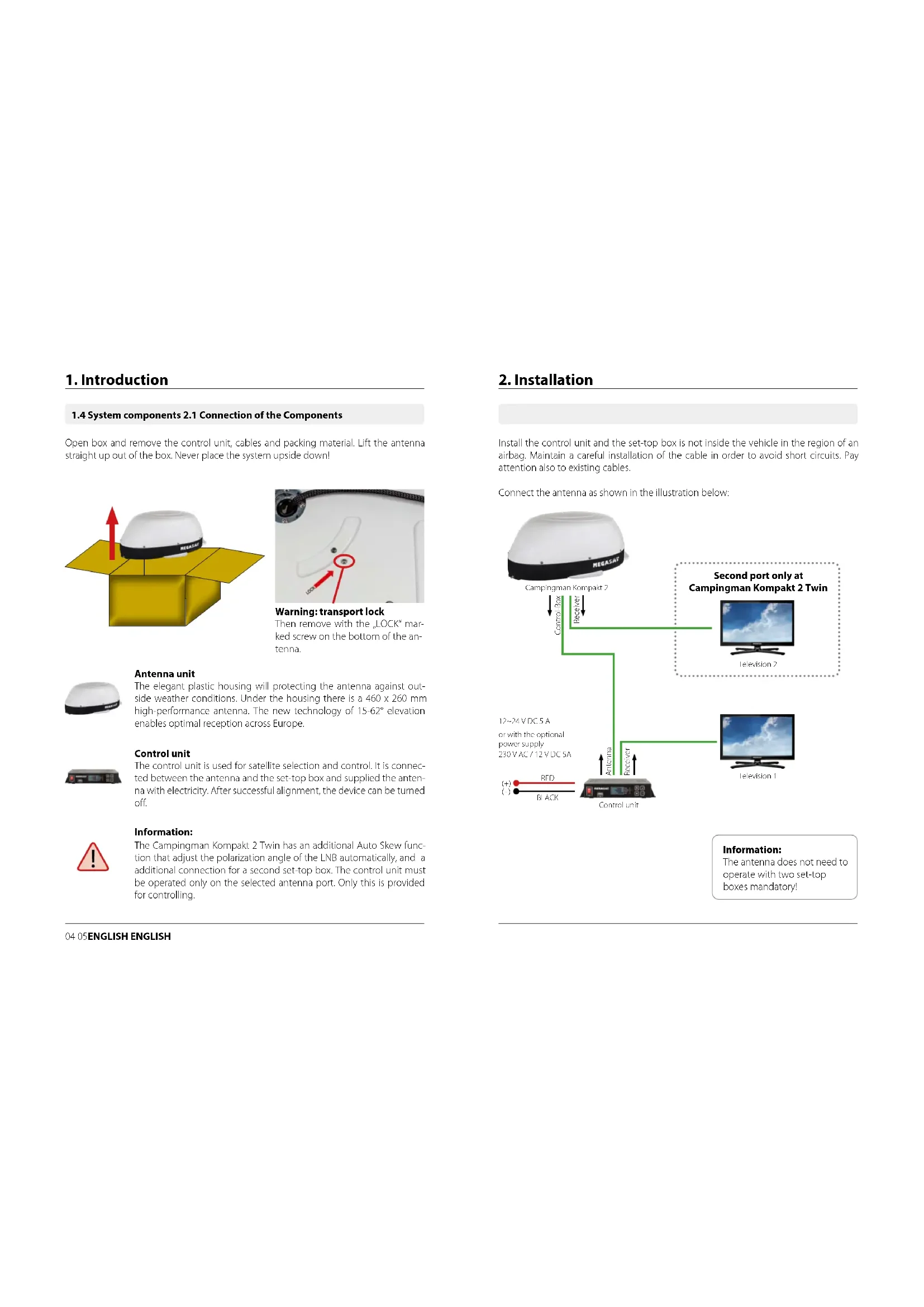
Open box and remove the control unit, cables and packing material. Lift the antenna straight up out of the box. Never place the system upside down!
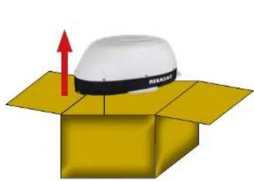
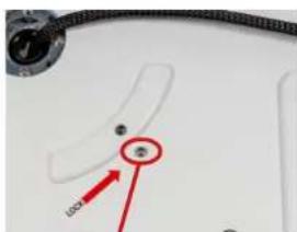
Warning: transport lock
Then remove with the LOCK mark- ked screw on the bottom of the antenna.
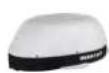
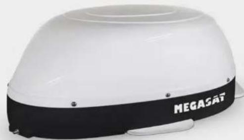
Antenna unit
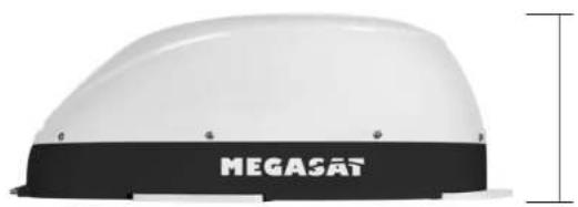
The elegant plastic housing will protecting the antenna against outside weather conditions. Under the housing there is a 460 × 260 mm high-performance antenna. The new technology of 15 - 62^st elevation enables optimal reception across Europe.
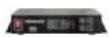
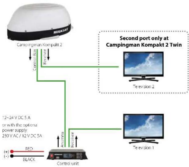
Control unit
The control unit is used for satellite selection and control. It is connected between the antenna and the set-top box and supplied the antenna with electricity. After successful alignment, the device can be turned off.

Information:
The Campingman Kompakt 2 Twin has an additional Auto Skew function that adjust the polarization angle of the LNB automatically, and a additional connection for a second set-top box. The control unit must be operated only on the selected antenna port. Only this is provided for controlling.
2. Installation
Install the control unit and the set-top box is not inside the vehicle in the region of an airbag. Maintain a careful installation of the cable in order to avoid short circuits. Pay attention also to existing cables.
Connect the antenna as shown in the illustration below:
Information:
The antenna does not need to operate with two set-top boxes mandatory!
2.2 Control unit

Warning:
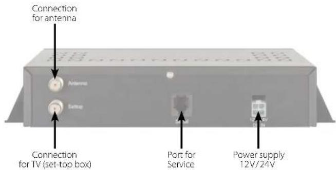
Connect the device only at a 7 amp protected line. The line must be at least 2.5mm^2 strong. (never directly to the car battery).
2. Installation2. Installation
2.3 Satellite broadcasting
Direct Broadcast Service (DBS) satellites broadcast audio, video and data information from satellites located 22,000 miles in space. A receiving station, such as the antenna, should include a dish and satellite receiver to receive the signals and process them for use by the consumer audio and video equipment. The system requires a clear view of the satellite to maximize the signal reception.
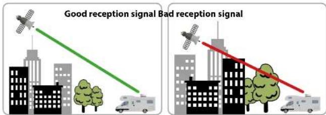
Objects such as tall lighthouse, bridges and big ship that block this view will cause a loss of signal. The signal will be quickly restored once the antenna has a clear line of sight again. Heavy rain, cloud, snow or ice may also interfere with the signal reception quality. If the satellite signal is lost due to blockage or severe weather condition, services from the receiver will be lost (picture will freeze frame and may disappear). When the satellite signal strength is again high enough, then the receiver will resume providing desired programming services.
2. Installation
2.4 Mounting on the roof
Basically, we recommend that you leave the installation to make by your dealer or workshop!

Warning:
Please also note that the antenna height of the vehicle will change accordingly! Please strictly adhere to the various points in the installation instructions!
General information:
Provide a suitable working environment, a garage/warehouse is better than open air. The ambient temperature for installation is between +5^ C and max. +25^ C. Work not directly in the sun. Comply with the safety regulations when handling with chemical products. Provide the necessary hygiene.
Preparation:
-
Make sure that the roof of your vehicle is sufficiently stable. In case of insufficient or doubtful roof stability is an approximately 2 mm thick plate with 100 × 100 cm is to be attached to the outer roof skin. Ask to your vehicle manufacturer.
-
Make sure that all parts are present. You may also need a roof penetration for the connecting cable of the antenna. This you get in specialist shops.
-
Place the antenna on the installation area and align it so that the antenna connection is not facing forward. Make sure that the mounting location is flat and do not interfere with roof constructions that can interfere with satellite reception. Constructions up to 8 cm in height do not matter, higher constructions should have a respective distance from the antenna, so that no barrier exists between the antenna and the satellite. The least distance to an air conditioner should be 30 cm.
-
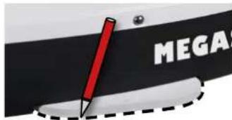
Clean the mounting surface with a suitable cleaner and a fleece cloth to remove dirt and impurities. Then draw the antenna feet with a pen.
-
Roughen the drawn areas and feet with sandpaper (120 grit) to easily and thoroughly clean the surface again with Cleaner (WARNING: then no longer touch areas) and let the clean dry for about 10 minutes.
2. Installation
- Unless you have a way to run the cable through an existing roof outlet, look for a suitable place (best in the wind shadow behind the antenna) on the roof for the installation of a roof outlet to avoid the ingress of moisture (eg rain or splash water) in the wellbore. Make sure that the cables are not curved too much to avoid signal loss and damage the cable (bending radius max. 5-7 cm).
2.5 Gluing instructions
1.Prepare the glue for mounting.
- Now take the glue on the underside of the antenna bases in serpentine lines, so that the glue can harden well to the inside.

-
Now place immediately (within 5 minutes after adhesive application), the antenna on the marked fields. Press your feet slightly and evenly and fix the antenna so that it stays in place, eg by an adhesive tape. It must be after pressing for at least 2mm glue between antenna and surface. The adhesive is cured max. in 48 hours at +18^ and a relative humidity of 50% . Should prevail low humidity during the assembly time, spray after bonding in the vicinity of the antenna always some water in the air.
-
Remove any spilled adhesive immediately with a putty knife or similar and clean the soiled surfaces with the cleaner and a fleece cloth.
-
For safety, you can attach the antenna bases additionally. Given by drill through the existing hole in the respective antenna to the roof of your car and fix it with a screw with locking nut. In order for the freshly bonded feet can not slip, wait with this work until the adhesive has cured.
-
After the complete assembly and curing of the adhesive, a silicone can be drawn around the antenna bases.
2. Installation 3. Firmware Update
2.4 Start up and operation
-
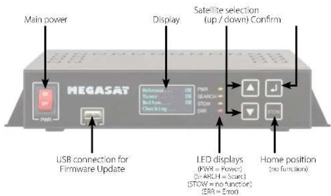
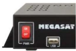
Turn on the control unit at the main switch. The green LED (PWR) on the control unit lights up - the boot process starts.
-
After booting the pre-installed satellites are displayed. Choose within 2 seconds the desired satellite with the satellite selection buttons (up / down).
-
The control unit checks whether all components are connected and the system is ready for operation. If the control unit found an error, the display shows "FAIL" behind the respective point and the red LED (ERR) is lit continuously. If everything is confirmed with OK now starts the search process. During the search operation, the yellow LED indicator (SEARCH) flashes.
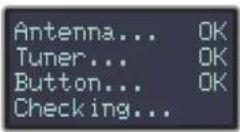
- After a successful search, the control unit displays the satellite list in the display, the yellow LED goes out and the display is dimmed.
Note:
To change the satellite, you can use the satellite selection buttons (up / down). The control unit starts searching again.
From time to time it happens that the firmware of the controller needs to be updated (eg. change a frequency of the satellite operator or general improvement of the control unit). You can find the latest firmware from our homepage www.megasat.tv
Update procedure
- Copy the firmware file to an appropriate USB stick. The USB flash drive should be formatted in FAT32 and do not include other files.
- Make sure that the control unit is turned off at the main switch.
- Insert the USB flash drive with the new firmware into the USB socket on the front.
- Now switch on the control unit. The control unit boots and starts the update process automatically. IMPORTANT: Do not turn off the control unit during the update procedure in order to avoid any damage!
- After a successful update, the control unit switches off and restarts automatically. The update process is now complete. The current firmware is displayed shortly after the boot process on the display.

4. Settings for the Skew 5. Trouble shooting
Skew setting values for European capitals
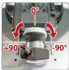
The following settings must be made only with Campingman Kompakt 2 (without Auto Skew).
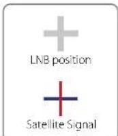
Signals in the vertical (red) and horizontal (blue) line have an offset of exactly 90^ to each other. Due to the different position of the satellites, depending on your location, it is possible that the signals do not meet exactly vertically and horizontally on the LNB. To adjust this, turn the LNB into the correct position to the transmitted signal. This adjustment to the LNB is called skew adjustment. The following illustration shows the optimal setting of the LNB. More accurate the match, the better of reception.
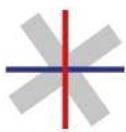
bad reception

good reception
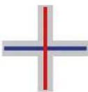
best reception
| Country City | Astra 2 | Astra 3 | Astra 1 | Hibotard | Hiripesat | Turkish | ||||
| Bulgaria | Serbia | +1.7 | -6.8 | +11.4 | +11.0 | -19.0 | +24.0 | +41.0 | -19.2 | |
| Denmark | Copenhagen | -8.4 | -0.4 | +2.5 | -0.3 | +6.3 | +8.1 | +24.8 | -18.5 | |
| Finland | Heikki | +5.2 | -7.9 | +10.3 | +6.8 | -11.2 | +14.2 | +25.2 | -9.5 | |
| France | Paris | -13.9 | -10.5 | -7.2 | -9.2 | -2.2 | +2.9 | +25.0 | -19.1 | |
| Germany | Berlin | -6.1 | -0.2 | +2.6 | +0.4 | +6.6 | +10.8 | +27.8 | -20.3 | |
| England | London | -13.7 | -10.7 | -7.8 | +10.3 | -7.0 | -6.6 | +21.6 | -26.1 | |
| Greece | Athens | +1.3 | -7.3 | +12.7 | +13.4 | -22.5 | +28.1 | +45.9 | -21.9 | |
| Hungary | Budapest | -1.3 | -3.0 | +6.9 | +5.6 | -12.8 | +17.5 | +84.7 | -19.6 | |
| Italy | Rome | -9.8 | -5.0 | -0.4 | -0.6 | +8.5 | +14.6 | +37.0 | -28.8 | |
| Poland | Warsaw | +1.5 | +5.1 | -8.4 | -6.1 | +12.2 | +16.2 | +31.0 | -15.5 | |
| Portugal | Lisbon | -30.2 | -17.0 | -73.7 | -25.3 | -16.8 | -10.1 | +24.9 | -14.7 | |
| Spain | Madrid | -24.8 | -71.2 | -17.6 | -18.7 | -9.9 | -8.7 | +77.5 | -60.1 | |
| Belgium | Brussels | -11.2 | -7.9 | -4.8 | -7.0 | -0.3 | +0.4 | +24.7 | -26.5 | |
| Sweden | Stockholm | +1.1 | +3.8 | -6.1 | -8.0 | +7.8 | +11.0 | +73.8 | -13.5 | |
| Switzerland | Bern | -11.3 | -7.5 | -8.8 | -5.2 | +2.4 | +7.8 | +79.5 | -27.9 | |
| Austria | Vienna | -3.4 | -0.7 | +7.5 | +3.0 | -10.2 | +15.0 | +32.9 | -71.1 |
No Signal
Objects such as trees, bridges, and large buildings, which are located in the angle of the satellite will lead to a loss of the signal.
If the satellite signal is lost through severe weather conditions, the current program of the receiver is stopped (the image freeze, or disappear). If the weather conditions allow a good reception again, the TV screen will be restored.
Displays on the control unit
Antenna (FAIL)
There is no connection to the antenna, or there are communication problems with the antenna. If necessary, check the coaxial line.
Tuner (FAIL)
There are problems with the tuner input of the control unit. Please contact a dealer for inspection.
Button (FAIL)
There are problems with the mainboard of the control unit. Please contact a dealer for inspection.
Satellite can't be found (only for Campingman without Auto Skew)
If the antenna has not found satellites, check the Skew settings for the satellite at your location. Please check the table of Skew settings. The basic setting of the LNB is 0^ . Should they deviate more than 5^ , adjust the degrees accordingly.
There is dirt on the antenna?
Excessive dirt on the housing may cause reception problems.
Everything is properly connected and turned on?
Your satellite TV receiver might be set up incorrectly or defective. First check the receiver's configuration to ensure it is set up for the desired programming. In the case of a faulty receiver, refer to your selected receiver's user manual for service and warranty information.
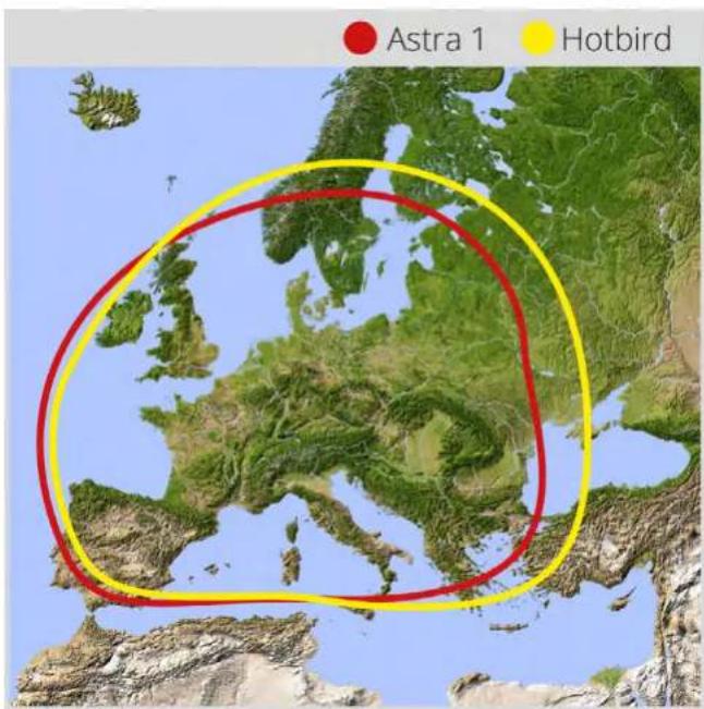
Satellite footprint
Satellites are positioned in fixed positions in orbit above the equator. To receive TV signals, the receiving location must be within the coverage area. Check reference to the graphic, if you are located in the footprint of the satellite. In the fringes of the footprint may lead to reception interference.
Satellite frequency data changed
If some channels work, while one or more other channels do not, or if the antenna cannot find the selected satellite, the satellite's frequency data might have changed.
6. Footprint 7. Mounting dimensions
Note:
In the outlying areas of the footprint there may be interference.
8. Specifications Conformity information
| Antenna type Off-Set-dish | |
| User | 1 (Campingman Kompakt 2) 2 (Campingman Kompakt 2 Twin) |
| LNB type | Universal LNB |
| Auto-Skew-Function only with Campingman Kompakt 2 Twin | |
| Frequency band Ku Band | |
| Frequency range 10.7 GHz to 12.75 GHz | |
| LNB gain | 33 dBi |
| Received power 49 dBW | |
| Polarization Vertical / Horizontal | |
| Motor control | 2-Axis DC Motor |
| Elevation 15° to 62° | |
| Azimuth 360° | |
| Rotational speed | 50° per second |
| Temperature range -25°C to +70°C | |
| Power supply | 12 VDC @5 Ampere |
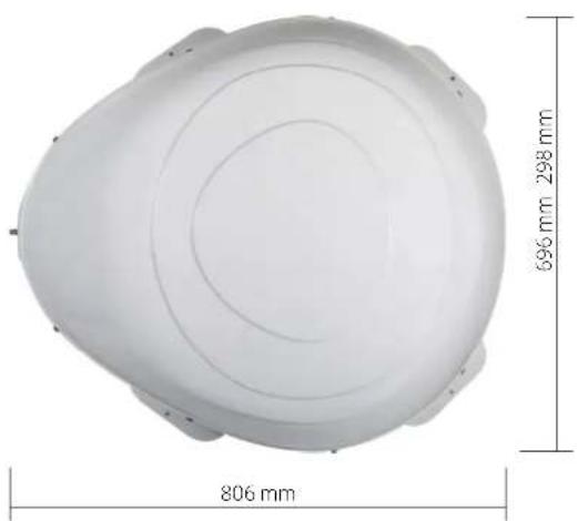
| Dimensions dish | 460 x 260 mm (W/H) |
| Dimensions antenna | 696 x 298 x 806 mm (W/H/D) |
| Weight antenna ca. 10 kg | |
| Dimensions control unit | 200 x 45 x 134 mm (W/H/D) |
| Weight control unit | ca. 617 g |
Note:
Weight and dimensions are not absolutely exact values. Technical details can be changed at any time without prior no
Hereby, Megasat Werke GmbH declares that the following product is in compliance with the essential requirements and other relevant provisions of directives 2014/30/EU (EMC), 2014/35/EU (LVD) and 2014/53/EU (RED):
Megasat Campingman Komapkt 2 (Article-No.1500183)
Megasat Campingman Kompakt 2 Twin (Article-No.1500184)
The declaration of conformity for this product is located at the company: Megasat Werke GmbH, IndustriestraBe 4a, D-97618 Niederlauer
The declaration of conformity can be downloaded from our homepage: www.megasat.tv/support/downloads
PRODUCT REGISTRATION
Registering your Megasat product gives you access to our automatic e-mail notifications. If your product requires new firmware, you will be notified by e-mail.
For registration please visit our homepage www.megasat.tv
You can find the form in Support Product registration
Version: 1.2 (February 2020) // Technical changes, misprint and errors reserved.
MegasatWere GmbH IndustriestraBe 4a D-9768 Niederlaer|www.megasattv|info@megasattv