
MWBOK15TB - Microwave FRIGIDAIRE - Free user manual and instructions
Find the device manual for free MWBOK15TB FRIGIDAIRE in PDF.
| Product type | Microwave with integrated hood (Over-the-Range) |
| Brand | Frigidaire |
| Model | MWBOK15TB |
| External dimensions | Approximately 30 in width x 15 in depth x 16 in height (estimate) |
| Weight | Approximately 25 kg (estimate) |
| Power supply | 120 V, 60 Hz, AC |
| Microwave power | Approximately 900 W (estimate) |
| Interior capacity | Approximately 1.5 ft³ (estimate) |
| Main functions | Microwave cooking, defrosting, reheating, auto cooking, integrated hood with ventilation |
| Installation | Wall mounting above a cooktop, mounting kit included (BOK) |
| Maintenance and cleaning | Clean the interior with a damp cloth and mild soap; the hood filter should be cleaned regularly |
| Safety | Child lock, automatic shut-off, door locking system |
| Spare parts and repairability | Parts available from the manufacturer; repair by a qualified technician recommended |
| General information | User and installation manual provided; compatible with 15 in deep cabinets |
Frequently Asked Questions - MWBOK15TB FRIGIDAIRE
User questions about MWBOK15TB FRIGIDAIRE
0 question about this device. Answer the ones you know or ask your own.
Ask a new question about this device
Download the instructions for your Microwave in PDF format for free! Find your manual MWBOK15TB - FRIGIDAIRE and take your electronic device back in hand. On this page are published all the documents necessary for the use of your device. MWBOK15TB by FRIGIDAIRE.
USER MANUAL MWBOK15TB FRIGIDAIRE
Installation Bump-Out Kit
For 15" Deep Cabinets
BEFORE YOU BEGIN
Read these instructions completely and carefully.
IMPORTANT:
Bump out kit installs with Over the Range models in which the serial number of the unit begins with KGXXXXXXXX. To verify proper unit, check the rating label located on the inside of the door. See below example:

- Save these instructions for local inspector's use.
- Observe all governing codes and ordinances.
- Note to Customer Keep these instructions for future reference.
- Skill level Installation of this appliance requires basic mechanical and electrical skills.
- Proper installation is the responsibility of the installer.
- Product failure due to improper installation is not covered under the Warranty.
Note to Installer – Be sure to leave these instructions with the consumer.
TOOLS YOU WILL NEED
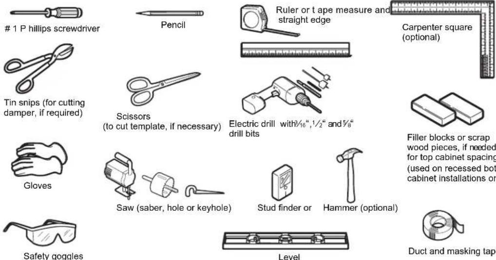
NOTE: For BOK installation – use hardware from over the range microwave unit which has 2 toogle bolts and 2 wood screws for mounting BOK. In addition, there are 2 toggle bolts in the BOK to complete proper installation.
MOUNTING SPACE
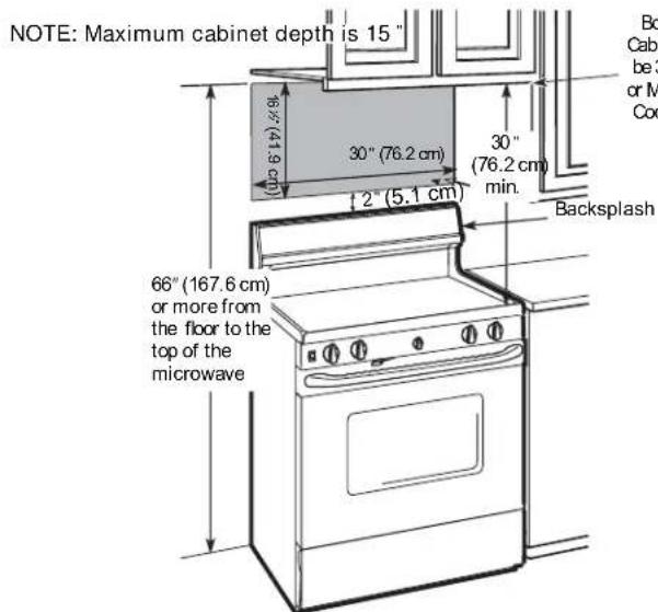
NOTES:
- The space between the cabinets must be 30"(76.2 cm) wide and free of obstructions.
• If you are going to vent your microwave oven to the outside, see Hood Exhaust Section for exhaust duct preparation. - When installing the microwave oven beneath smooth, flat cabinets, be careful to follow the instructions on the top cabinet template for power cord clearance.
DAMAGE - SHIPMENT/INSTALLATION
- If the unit is damaged in shipment, return the unit to the store in which it was bought for repair or replacement
- If the unit is damaged by the customer, repair or replacement is the responsibility of the customer
- If the unit is damaged by the installer (if other than the customer), repair or replacement must be made by arrangement between customer and installer
IMPORTANT:
- Move the top cabinet template that comes with your OTR microwave 2.25forward when installing from bac wall.
• Use the rear wall template that comes with your OTR microwave to identify mounting location for the bump out kit.
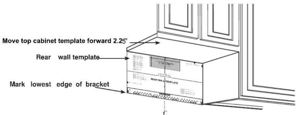
Place the Bump Out Kit Bracket in place of rear wall template location making sure that the bottom edge lines up.
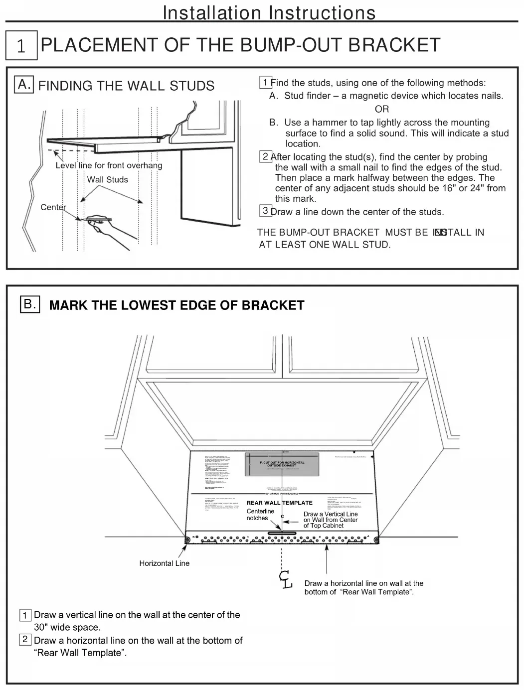
1 PLACEMENT OF THE BUMP-OUT BRACKET
A. FINDING THE WALL STUDS
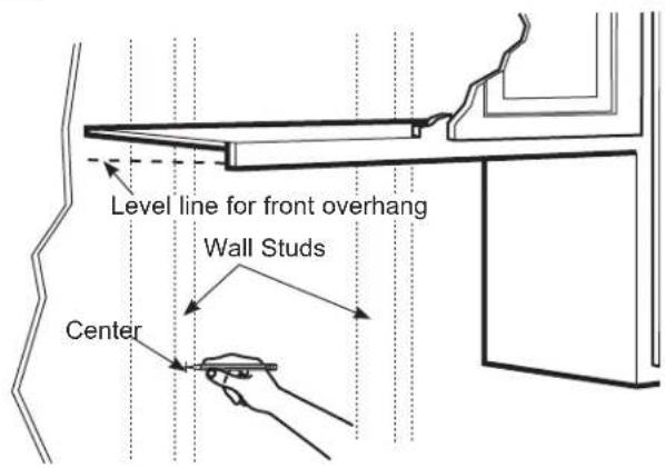
1 Find the studs, using one of the following methods:
A. Stud finder – a magnetic device which locates nails.
OR
B. Use a hammer to tap lightly across the mounting surface to find a solid sound. This will indicate a stud location.
2 After locating the stud(s), find the center by probing the wall with a small nail to find the edges of the stud. Then place a mark halfway between the edges. The center of any adjacent studs should be 16" or 24" from this mark.
3 Draw a line down the center of the studs.
THE BUMP-OUT BRACKET MUST BE INSTALL IN AT LEAST ONE WALL STUD.
B. MARK THE LOWEST EDGE OF BRACKET
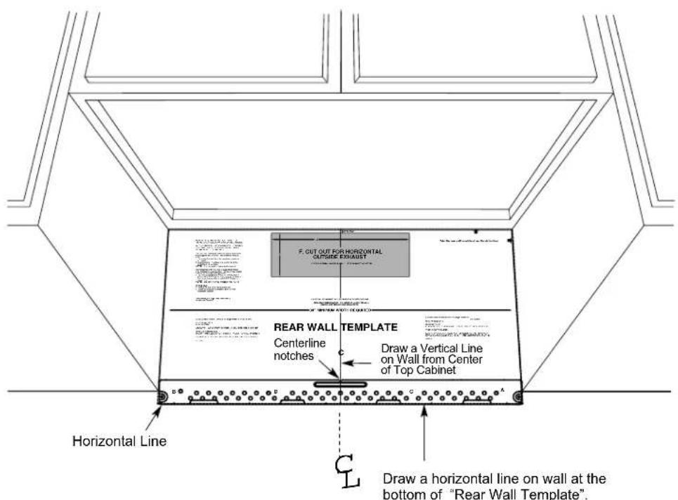
1 Draw a vertical line on the wall at the center of the 30" wide space.
2 Draw a horizontal line on the wall at the bottom of "Rear Wall Template".
1 PLACEMENT OF THE BUMP-OUT BRACKET
C. ALIGNING THE WALL PLATE
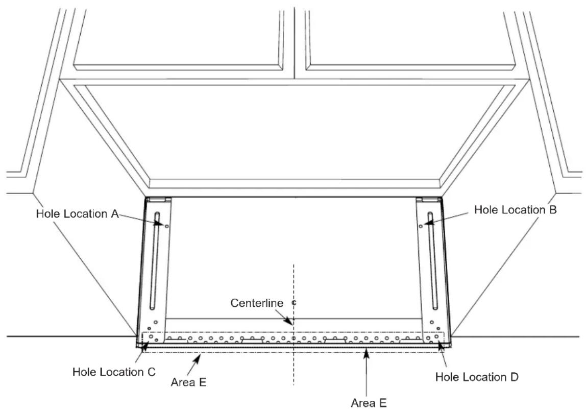
1 Place mounting plate on the wall, making sure that the bottom of mounting plate is touching the horizontal line drawn with rear template. Line up the notch and center line on the mounting plate to the center line on the wall.
2 While holding mounting plate with one hand, draw circles on the wall at holes A, B, C and D (see illustration above Four holes must be used for mounting.
NOTE: Holes C and D are inside area E. If neither C nor D is in a stud, find a stud somewhere in area E and draw a fifth circle to line up with the stud. It is important to use at least one wood screw mounted firmly in a stud to support the weight of the oven. Set the mounting plate aside.
3Drill holes on the circles. If there is a stud, drill a 316 " hole for wood screws. For holes that don't line up with a stud, drill a 58 " hole for toggle bolts. NOTE: DO NOT MOUNT THE PLATE AT THIS TIME.
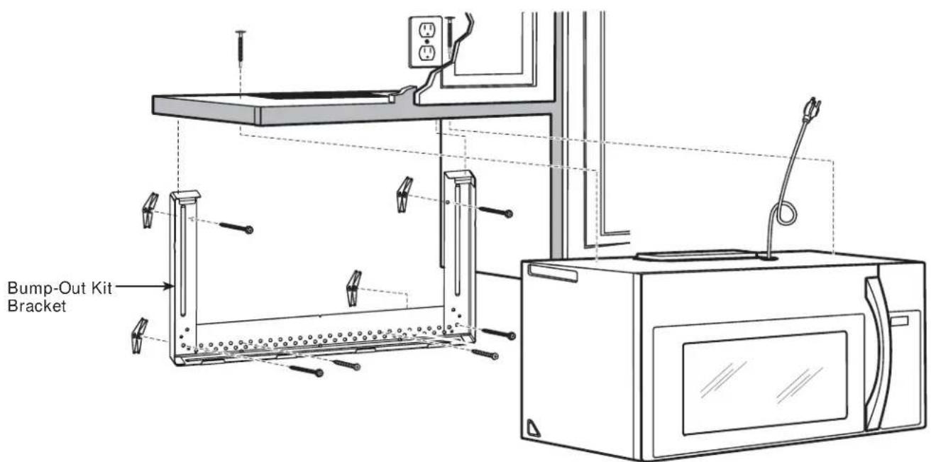
2 | INSTALLING THE BUMP-OUT BRACKET
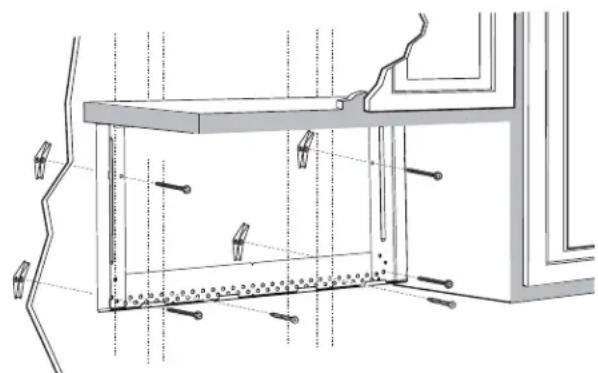
A. ATTACH THE MOUNTING PLATE TO THE WALL
natural_image
Technical line drawing of a structural frame with supports and hidden lines (no text or symbols)Attach the plate to the wall using4 toggle bolts. At least one wood screw must be used to attach the plate to a wall stud. NOTE: Use hardrow ATR packaging and bump out kit packaging.
1 Remove the toggle wings from the bolts.
2 Insert the bolts into the mounting plate through the holes designed to wall and reattach the toggle wings to 34 " onto each bolt.
To use toggle bolts:
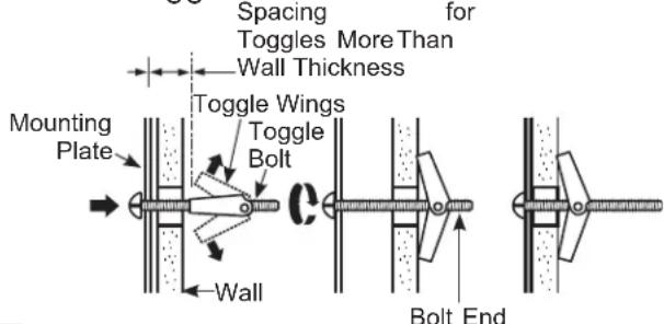
3 Place the mounting plate against the wall and insert the toggle wings into the holes in the wall to mount the plate.
NOTE: There are two things to be noted before tightening toggle bolts and wood screw. First, make sure the tabs on the mounting plate touch the bot tom of the cabinet when pushed flush against the wall. Second, make sure the plate is properly centered under the cabinet.
CAUTION: Becareful to avoid pinching fingers between the back of the mounting plate and the wall.
4 Tightenall bolts. Pull the plate away from the wall to help tighten the bolts.
NOTE :
1、Refer to the over the range installation instructions to finish installation of unit.
2、When BOK is mounted to larger cavity OTR models( like 1.8 / 2.1 models), the sides of BOK will not go all the way to top, and the gap is about 0.91" to the cabinet.
Installation Le KitBump-Out
Instructions
1 PLACEMENT DU SUPPORT DE BUMP-OUT
A. TROUVER LES POTEAUX MURAX
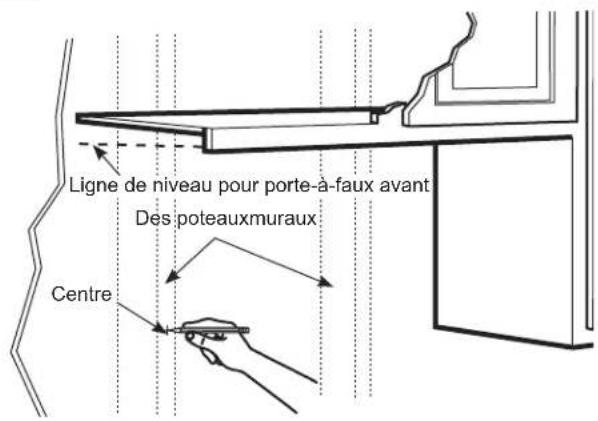
1 Trouvez les poteaux, using one of the following methods:
natural_image
Architectural cross-section diagram of a window frame with structural elements and lighting fixtures (no text or labels)natural_image
Technical line drawing of a structural frame with mounting brackets and vertical supports (no text or symbols)Brand : FRIGIDAIRE
Model : MWBOK15TB
Category : Microwave