
VC292 - Multimeter VOLTCRAFT - Free user manual and instructions
Find the device manual for free VC292 VOLTCRAFT in PDF.

| Product type | Digital multimeter with clamp meter |
| Brand/Model | Voltcraft VC292 |
| Measurement category | CAT III 600 V |
| Max voltage (AC/DC) | 600 V |
| Max current (contact) | 600 mA (via μA/mA terminals) |
| Max current (clamp) | 60 A AC/DC |
| Display | Digital screen 6000 counts |
| Multimeter power supply | 3 AAA 1.5 V batteries |
| Clamp power supply | 2 AAA 1.5 V batteries |
| Total weight (with clamp) | Approx. 559 g |
| Dimensions (estimated) | Approx. 180 x 85 x 50 mm |
| Measurement functions | AC/DC voltage, AC/DC current (contact and clamp), resistance, capacitance, frequency, diode test, continuity test, NCV, LoZ, pulse measurement |
| Protection | Self-resetting PTC fuses and ceramic fuse F2 (2.5 A/700 V) |
| Safety | Wrong connection alarm, dangerous voltage indicator, auto power off |
| Maintenance | Clean with non-lint damp cloth; annual calibration recommended |
| Included accessories | CLA60 transformer clamp, 2 test leads, protective caps, 5 AAA batteries, user manual |
Frequently Asked Questions - VC292 VOLTCRAFT
User questions about VC292 VOLTCRAFT
0 question about this device. Answer the ones you know or ask your own.
Ask a new question about this device
Download the instructions for your Multimeter in PDF format for free! Find your manual VC292 - VOLTCRAFT and take your electronic device back in hand. On this page are published all the documents necessary for the use of your device. VC292 by VOLTCRAFT.
USER MANUAL VC292 VOLTCRAFT
GB Operating Instructions
VC292 Digital Multimeter
Item No. 2576863 Page 57 - 110
F Mode d'emploi
5 Symbol-Erklärung

natural_image
Pure electrical circuit lines without any symbols
natural_image
Diagram of a magnetic circuit with rotating coil, magnetic field lines, and a cross symbol (no text or labels)
natural_image
Illustration of a solenoid with magnetic field lines and a magnified view of its surface (no text or symbols)natural_image
Technical line drawing of a mechanical housing or enclosure with internal components (no text or symbols)2 Introduction....59
3 Delivery content....59
4 Up-to-date operating instructions....59
5 Description of symbols....60
6 Intended use....61
7 Safety instructions ....63
7.1 (Rechargeable) batteries 65
7.2 Connected devices....65
7.3 LED light 65
8 Product description....66
9 Product overview....67
10 Control dial 68
11 Display elements and symbols....69
11.1 Elements....69
11.2 Symbols 70
12 Taking measurements....72
12.1 Switching the multimeter on and off....73
12.2 Incorrect measurement socket warning....74
12.3 Measure AC voltage "V \~" 75
12.4 Measure mV/AC voltage "mV" 76
12.5 Measure DC voltage ("V")....77
12.6 Measure mV/DC voltage ("mV")....78
12.7 LoZ voltage mode....78
12.8 Contactless clamp current measurement "A".....79
12.9 Contacted current measurement up to 600 mA....83
12.10 Frequency measurement....86
12.11 Measurement of pulse duration in % 87
12.12 Resistance measurement 88
12.13 Diode test....89
12.14 Continuity test ....90
12.15 Capacitance measurement....91
12.16 Non-contact AC voltage test "NCV" 92
13 Additional functions....93
13.1 SEL function....93
13.2 Torch....93
13.3 REL function .....93
13.4 HOLD function 94
13.5 Auto power-off function....94
14 Cleaning and maintenance....95
14.1 General information....95
14.2 Cleaning....95
14.3 Opening the battery/fuse compartment 96
14.4 Inserting/changing the battery 97
15 Disposal....99
15.1 Product 99
15.2 (Rechargeable) batteries 99
16 Troubleshooting....101
17 Technical data....102
17.1 Multimeter VC292....102
17.2 CLA60 clamp transformer....103
2 Introduction
Dear customer,
Thank you for purchasing this product.

These operating instructions are part of this product. They contain important notes on commissioning and handling. Also consider this if you pass on the product to any third party. Therefore, retain these operating instructions for reference!
If there are any technical questions, please contact: www.conrad.com/contact
3 Delivery content
Digital multimeter
CLA60 clamp transformer
2x safety test leads with CAT III protective caps
5x AAA 1.5 V batteries
Operating instructions
4 Up-to-date operating instructions
Download the latest operating instructions at www.conrad.com/downloads or scan the QR code shown. Follow the instructions on the website.

5 Description of symbols

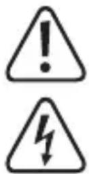
The symbol warns of hazards that can lead to personal injury.
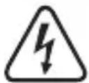
The symbol warns of dangerous voltage that can lead to personal injury by electric shock.
The arrow symbol indicates special information and advice on how to use the product.

This product has been CE tested and complies with the necessary national and European regulations.

This device is UK conformity assessed and meets applicable Great Britain directives.

Protection class 2 (double or reinforced insulation, protective insulation)
CAT II
It is applicable to test and measuring circuits connected directly to utilization points (socket outlets and similar points) of the low-voltage MAINS installation.
CAT III
It is applicable to test and measuring circuits connected to the distribution part of the building's low-voltage MAINS installation.
CAT IV
Measurement Category IV: For measuring at the origin of a low-voltage installation (e.g. mains distribution, electricity provider's transfer points to homes) and outdoors (e.g. when conducting tasks on underground cables or overhead lines). This category also includes all lower categories. Measuring in CAT IV is only permitted with test prods with a maximum free contact length of 4 mm or with cover caps over the test prods.

Earth potential

Direct current
Alternating current
6 Intended use
Measures and displays electrical parameters in measurement category CAT III (up to 600 V).
Complies with the EN 61010-1 and EN 61010-2-033 standards and all lower categories.
The multimeter must not be used in the measuring category CAT IV.
Measures direct and alternating voltages up to 600 V
Direct measurement of direct and alternating currents up to 600 mA
Contactless measurement of direct and alternating currents up to 60 A with a CLA60 clamp transformer
Measures frequency from 10 Hz to 10 MHz (max. 20 Vrms)
Measures capacitance up to 60 mF
Measures resistance up to 60 MΩ
Continuity tests (<10 Ω acoustic)
Diode tests
The measurement modes are selected using the rotary control. In many measurement ranges, measurement range selection is automatic (except for continuity testing, diode testing and current measurement ranges).
Effective (True RMS) measurements are displayed when measuring AC voltages/currents with a frequency of up to 400 Hz. This ensures that sinusoidal and non-sinusoidal voltage/currents are measured accurately.
Negative polarity readings are indicated with the (-) sign.
A low-impedance mode (LoZ) enables voltage measurement with reduced internal resistance. This suppresses phantom voltages, which may occur in high-impedance measurements. Measurement with reduced impedance is only permissible in measurement circuits of up to 250 V and for up to 3 s.
The two current measurement inputs are protected against overload. The voltage in the measurement circuit must not exceed 600 V.
The current clamp measurement input is equipped with 2x maintenance-free self-resetting PTC fuse and one ceramic tube fuse.
The mA/ A measurement input is equipped with a maintenance-free self-resetting PTC fuse and one ceramic tube fuse, which can be used in the case of conventional overload mis-operation of less than about 5A, the current is limited and the meter is well protected. When the meter is being used for mA/ A measurement, but the meter is mistakenly connected to a high-energy high-voltage power supply, then the ceramic tube fuse will work and probably blow to protect the meter. In such case, the blown ceramic tube fuse is required to be replaced by a new one.
The multimeter is powered by standard 3x AAA 1.5 V batteries. The current clamp requires two standard micro batteries (AAA, LR3 or equivalent). The device may only be operated with the specified batteries. Due to their low capacity and partly lower cell voltage, rechargeable batteries should not be used.
The device switches off automatically after 15 minutes if no buttons are pressed. This prevents the battery from draining. The automatic shut-off function can be disabled.
There is a fold-out stand on the rear of the device. This allows the multimeter to be positioned for optimum readability.
Do not use the multimeter and current clamp when the battery compartment is open or when the battery compartment cover is missing.
Do not take measurements in potentially explosive areas, damp rooms or adverse conditions. Adverse conditions include: Moisture or high humidity, dust and flammable gases, vapours or solvents, thunderstorms and strong electromagnetic fields.
For safety reasons, only use test leads or accessories that match the multimeter's specifications.
The multimeter may only be used by people who are familiar with the relevant regulations and understand the potential hazards. The use of personal protective equipment is recommended.
7 Safety instructions
Read the operating instructions carefully and especially observe the safety information. If you do not follow the safety instructions and information on proper handling in this manual, we assume no liability for any resulting personal injury or damage to property. Such cases will invalidate the warranty/guarantee.
This device was shipped in a safe condition.
To ensure safe operation and avoid damaging the device, always observe the safety information and warnings in these instructions.
The unauthorised conversion and/or modification of the device is not permitted for safety and approval reasons.
Check that the measuring device is functioning correctly with a known source before using it.
Consult a technician if you are not sure how to use or connect the device.
Measuring instruments and their accessories are not toys and must be kept out of the reach of children.
Always comply with the accident prevention regulations for electrical equipment when using the product in commercial facilities.
In schools, educational facilities, hobby and DIY workshops, the multimeter must be used under the responsible supervision of qualified personnel. The same applies when the multimeter is used by people with reduced physical and mental capabilities.
Always ensure that the multimeter is set to the correct measurement mode before taking a measurement.
When using measuring probes without protective caps, measurements between the multimeter and the earth potential must not exceed the CAT II measurement category.
When taking CAT III measurements, the cover caps must be placed on the probe tips (max. length of
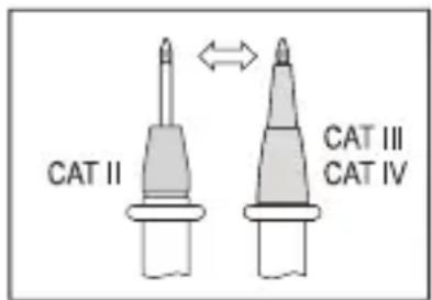
exposed contacts = 4 mm) to avoid accidental short circuits. These are supplied with the device.
Always remove the measuring probes from the measured object before changing the measurement range.
The voltage between the multimeter connection points and earth must never exceed 600 V DC/AC in CAT III.
Exercise particular caution when working with voltages higher than AC 30 Vr.m.s, 42.4 V peak or DC 60 V. Touching electrical conductors with these voltages may cause a fatal electric shock.
To prevent an electric shock, do not touch the connections/measuring points when taking measurements, either directly or indirectly. When taking measurements, do not touch any exposed areas beyond the grip markings on the measuring probes and the clamp transformer.
Check the multimeter and test leads for signs of damage before each measurement. Never take measurements if the protective insulation is damaged (torn, missing, etc.). The test leads come with a wear indicator. A second layer of insulation will become visible if the lead is damaged (the second layer of insulation is a different colour). If this occurs, discontinue use and replace the measurement accessory.
Do not use the multimeter just before, during or just after an electrical storm (electric shock /high-power surges!). Ensure that your hands, shoes, clothes, the floor, circuit and circuit components are dry.
Avoid using the device in the immediate vicinity of:
– Strong magnetic or electromagnetic fields
- Transmitting antennas or HF generators.
These may distort the measurements.
If you suspect that safe operation is no longer possible, discontinue use immediately and prevent unauthorized use. Safe operation can no longer be assumed if:
– There are signs of damage
– The device does not function properly
- The device was stored under unfavourable conditions for a long period of time
– The device was subjected to rough handling during transport
Do not switch the device on immediately after it has been brought from a cold room into a warm one. The condensation generated may destroy the product. Leave the device switched off and allow it to reach room temperature.
Do not leave packaging material lying around carelessly, as it may become a dangerous toy for children.
Observe the safety information in each section.
Before each use verify tester operation by measuring a known voltage.
7.1 (Rechargeable) batteries
Correct polarity must be observed while inserting the (rechargeable) batteries.
The (rechargeable) batteries should be removed from the device if it is not used for a long period of time to avoid damage through leaking. Leaking or damaged (rechargeable) batteries might cause acid burns when in contact with skin, therefore use suitable protective gloves to handle corrupted (rechargeable) batteries.
(Rechargeable) batteries must be kept out of reach of children. Do not leave (rechargeable) batteries lying around, as there is risk, that children or pets swallow them.
All (rechargeable) batteries should be replaced at the same time. Mixing old and new (rechargeable) batteries in the device can lead to (rechargeable) battery leakage and device damage.
(Rechargeable) batteries must not be dismantled, short-circuited or thrown into fire. Never recharge nonrechargeable batteries. There is a risk of explosion!
7.2 Connected devices
Also observe the safety and operating instructions of any other devices which are connected to the product.
7.3 LED light
Attention, LED light:
Do not look directly into the LED light!
Do not look into the beam directly or with optical instruments!
8 Product description
The multimeter (DMM) displays measurements on a digital display. The multimeter has 6000 counts (count = smallest display value). The correct socket assignment is displayed according to the measurement mode selected. Incorrect socket assignment is indicated by a warning sound and warning indicator. This increases the operational safety of the multimeter for the user.
The DMM can be used to take measurements up to CAT III 600 V. It is suitable for use in hobby and professional applications.
With this multimeter, you do not requently need to replace a fuse that has accidentally tripped in the mA/μA measurement range. The built-in PTC protection elements limit current flow in the event of an overload and thus protect the multimeter and the current circuit. The PTC protection elements reset themselves after tripping and a short cool-down period. For this, the current measurement circuit must only be interrupted briefly.
When the meter is being used for mA/ A measurement, but the meter is mistakenly connected to a high-energy high-voltage power supply, then the ceramic tube fuse will work and probably blow to protect the meter. In such case, the blown ceramic tube fuse is required to be replaced by a new one.
An external clamp transformer allows direct and alternating currents of up to 60 A to be measured contactlessly without interrupting the current circuit. The measurement input is equipped with a maintenance-free PTC protection element to protect against overload.
The battery and fuse compartment can only be opened when all test leads have been removed from the multimeter. When the battery and fuse compartment are open, the test leads cannot be inserted into the measurement sockets. This is a built-in safety feature designed to protect the user.
9 Product overview
9.1 Multimeter
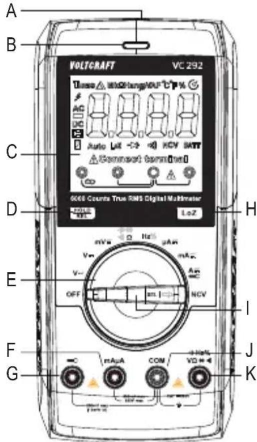
A. Non-contact voltage sensor
B. Tri-color indicator LED
C. Display
D. HOLD/REL button
E. Rotary control for selecting the measurement mode
F. mAμA measurement socket
G. measurement socket for clamp transformer (+)
H. LoZ Low impedance 400 kΩ button for changing the impedance
I. SEL/ button
J. COM measurement socket (reference potential, "negative")
K. measurement socket ("positive potential" for direct voltages)
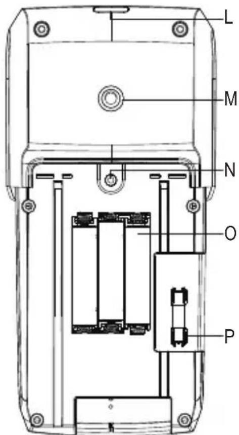
L. LED light
M. Connection thread for stand
N. Battery compartment screw
O. Battery compartment
P. Self-resetting PTC and ceramic tube fuse protection elements for "mAμA" measurement input
9.2 Clamp
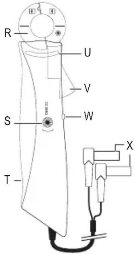
R. Current clamp sensor
S. Adjuster for DC zero calibration
T. Battery compartment (at rear)
U. Tangible grip range marking
V. Clamp opening lever
W. Operating switch
X. Safety connection plug
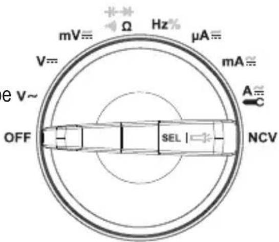
10 Control dial
Use the control dial to select the measurement mode.
Automatic range selection ("Autorange") is enabled and the range will be automatically selected.
→ The measurement ranges must be selected manually.
→ Always start with the largest measurement range, and then switch to a smaller range if necessary.
The control dial features a function button.
→ Use the SEL/☐ button to switch to sub-modes when the measuring mode has more than one function
To turn the multimeter off, move the control dial to the OFF position. Always turn the multimeter off when it is not in use.
11 Display elements and symbols
The following symbols and letters appear on the device/display. Other symbols may appear on the display (display test), but these have no function.
11.1 Elements
| Element Description | |
| TRMS | True RMS measurement |
 | Delta symbol for relative measurement (= reference measurement) |
| M Mega symbol (exp.6) | |
| k Kilo symbol (exp.3) | |
| [ZYST] | |
| HZ Hertz (unit of frequency) | |
 | |
 | |
 | |
 | |
 | |
 | |
 | Display of the pulse duration of the positive half-wave as a percentage (pulse-pause ratio) |
 | Automatic shut-off is enabled |
 | Diode test symbol |
 | Acoustic continuity tester symbol |
| LoZ Low impedance symbol | |
| Connect terminal | Correct socket assignment indicator |
| Auto Automatic measurement range selection is enabled | |
 | Battery replacement indicator |
 | Hold function is enabled |
| DC Direct current symbol ( ) | --- |
 | Polarity indicator for current flow direction (negative terminal) |
| AC Alternating current symbol ( ) | ~ |
 | Warning symbol for dangerous voltage |
 | Symbol for current measurement with current clamp |
11.2 Symbols
| Symbol Description | |
| REL Relative measurement button (= reference measurement) | |
| SELECT Switch to sub-mode | |
| HOLD Freezes the current measurement | |
| OL Overload = The measurement range was exceeded | |
| LEAd “Incorrect socket” warning | |
| OFF “Meter OFF” switch position | |
| ON “Meter ON” switch position | |
 | Diode test symbol |
 | Acoustic continuity tester symbol |
 | Capacity measurement range symbol |
 | Alternating current symbol |
 | Direct current symbol |
| COM Connection for reference potential | |
| mV Millivolt mode (exp. -3) | |
| V Voltage mode (Volt = unit of electrical voltage) | |
| A Current mode (Ampere = unit of electric current) | |
| mA Milliamp mode (exp. -3) | |
| μA Microamp mode (exp. -6) | |
| Hz Frequency mode (Hertz = unit of frequency) | |
| Ω Resistance mode (Ohm = unit of electrical resistance) | |
| TRMS True root mean square measurement | |
| + Polarity indicator for current flow direction (positive terminal) | |
| - Polarity indicator for current flow direction (negative terminal) | |
 | Symbol for current measurement with current clamp |
12 Taking measurements

Never exceed the maximum permitted input values. Never touch circuits or circuit components if they may carry voltages greater than AC 30 Vr.m.s, 42.4 V peak or DC 60 V! This may cause a fatal electric shock!
Measurements can only be taken when the battery and fuse compartment is closed. Cables cannot be inserted when the compartment is open.
Before measuring, check the connected test leads for damage, such as cuts, tears and kinks. Never use damaged test leads, as this may cause a fatal electric shock!
When taking measurements, do not touch any area beyond the grip markings on the test probes / test leads.
Only connect the two test leads that you require to take measurements. For safety reasons, remove all unnecessary test leads from the device before taking a measurement.
Measurements in circuits rated at AC 30 Vr.m.s, 42.4 V peak or DC 60 V must only be made by qualified and trained personnel who are familiar with the relevant regulations and the associated hazards.
→ “OL” (overload) indicates that the measuring range has been exceeded.
The display shows the corresponding connection sequence of the measurement sockets for each measurement mode. Observe this when connecting the test leads to the multimeter.
12.1 Switching the multimeter on and off Multimeter
- Turn the control dial to select the desired mode.
→ The optical measuring range is automatically selected (except in current mode).
→ When measuring a current, always start with the largest measurement range, and then switch to a smaller range if necessary.
→ Always disconnect the leads from the multimeter before switching to another mode.
- To turn the multimeter off, move the control dial to the OFF position.
→ Always turn the multimeter off when it is not in use.
- Before storing the multimeter, insert the test leads into the high-impedance terminals (COM and +1 - Hz%V + + ). This helps to prevent errors when making subsequent measurements.

The battery must be inserted before you can use the multimeter. See "Cleaning and maintenance" for instructions on how to change/replace the battery.
Clamp transformer
Use the slide switch to switch the clamp transformer on/off. To switch the clamp transformer on, slide the switch to the ON position. Operational readiness is indicated by a switch lit up red.
To switch off, move the slide switch to the OFF position. Always switch the clamp transformer off when it is not in use.

Insert the batteries before using the multimeter and clamp transformer. For more information on inserting/replacing the batteries, see “Cleaning and maintenance”.
12.2 Incorrect measurement socket warning
Measurement socket monitoring is integrated into the DMM. If the test leads are connected to the wrong sockets (which can be dangerous for the user and damage the DMM), the DMM triggers an acoustic and optical alarm.
As soon as the test leads are inserted into the current measurement sockets and another measurement mode (excluding current measurement) is selected, the DMM emits a piercing warning sound. This is also the case if the measurement input between the current clamp socket and mAμA socket is swapped.
If the alarm is triggered and "LEAd" appears on the display, check that the leads are connected to the correct sockets and that you have selected the correct measurement mode
The multimeter triggers the alarm when the sockets are connected as follows:
| Measurement mode | V/mV/Ω/Hz/→→→→→→→→→→→→→→→→→→→→→→→→→→→→→→→→→→→→→→→→→→→→→→→→→→→→→→→→→→→→→→→→→→→→→→→→→→→→→→→→→→→→→→→→→→→→→→→→→→→→ | mA/μA | 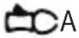 |
| Connected sockets | mA/μA/→→→→→→→→→→→→→→→→→→→→→→→→→→→→→→→→→→→→→→→→→→→→→→→→→→→→→→→→→→→→→→→→→→→→→→→→→→→→→→→→→→→→→→→→→→→→→→→→→→ | → | mA/μA |

Interrupt the test setup immediately in the event of an alarm and check that the correct measurement mode/measurement connection have been selected. The display also indicates the correct measurement sockets to use for each measurement range.
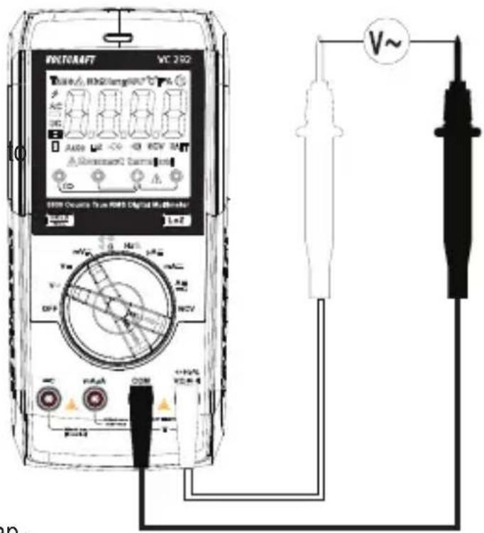
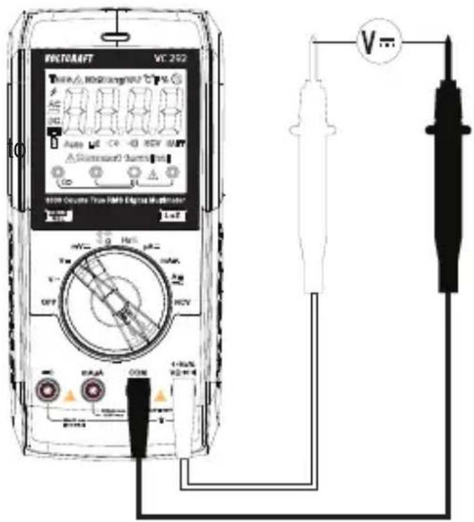
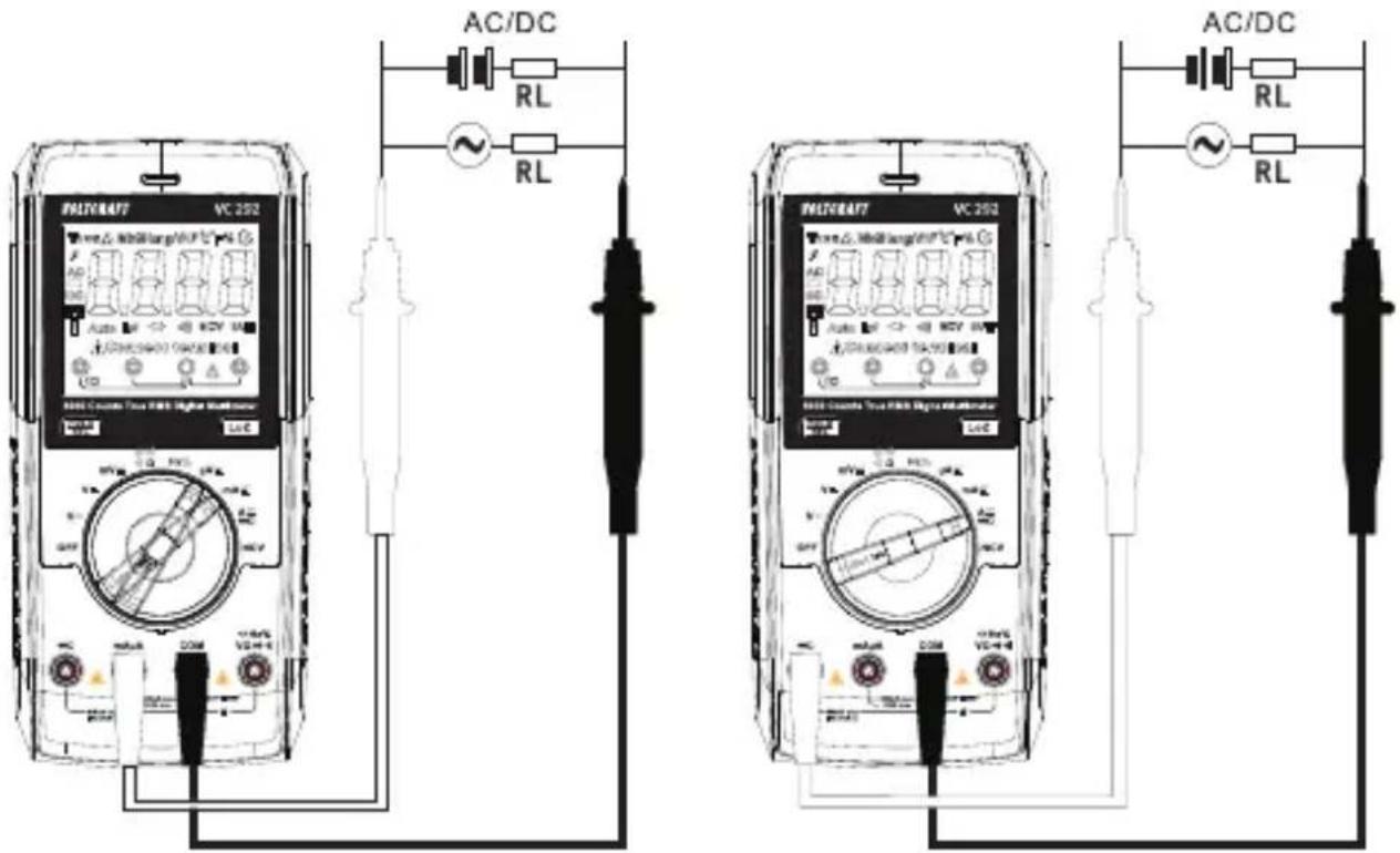
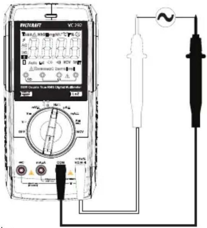
12.3 Measure AC voltage "V\~
Proceed as follows to measure "V/AC" voltages:
- Switch the DMM on and select the V measurement mode. "AC" and "V" will appear on the display.
→ For lower voltages up max. 600 mV, select the mV \~ measurement range.
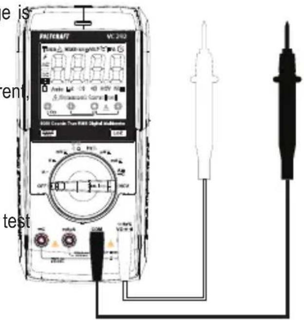
- Insert the red lead into the V socket and the black lead into the COM socket.
- Connect the two measuring probes in parallel to the object that you want to measure (e.g. generator or circuit).
→ The measurement will appear on the display.
- After taking a measurement, remove the leads from the measured object and switch the DMM off.
The voltage measurement range "V/AC" has an input resistance of ≥ 10 M . This (almost entirely) prevents a load on the circuit.
12.4 Measure mV/AC voltage "mV"\~
Proceed as follows to measure "mV/AC" voltages:
- Switch the DMM on and select mV-mode. "DC" and "mV" will appear on the display.
- Press the SEL/ button on the rotary control to switch to "AC" mode.
→ “AC”, “TRMS” and “mV” will appear on the display.
- Insert the red lead into the V socket and the black lead into the COM socket.
- Connect the two measuring probes in parallel to the object that you want to measure (e.g. generator or circuit).
→ The measurement will appear on the display.
- After taking a measurement, remove the leads from the measured object and switch the DMM off.
The voltage measurement range “mV/AC” has an input resistance of ≥100 MΩ. This (almost entirely) prevents a load on the circuit.
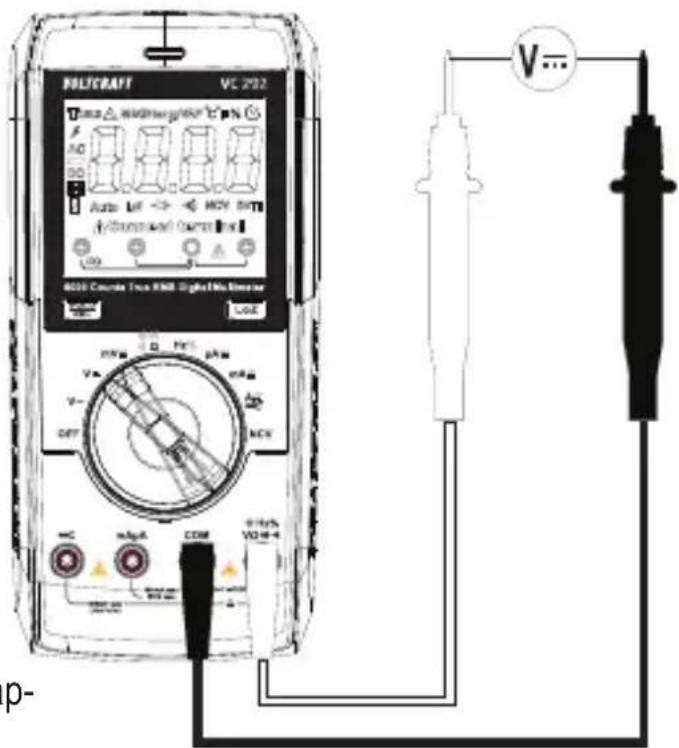
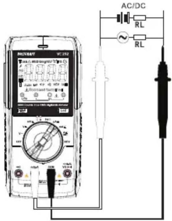
12.5 Measure DC voltage ("V=")
Proceed as follows to measure "DC" direct voltages:
- Switch the DMM on and select the V--measurement mode. "DC" and "V" will appear on the display.
→ For lower voltages up max. 600 mV, select the mV --- measurement range.
- Insert the red lead into the V socket and the black lead into the COM socket.
- Connect the two measuring probes in parallel to the object that you want to measure (e.g. battery or circuit). Connect the red measuring probe to the posi-
tive terminal and the black measuring probe to the negative terminal.
→ The polarity of the measurement is indicated on the display.
If “-” appears in front of a direct voltage measurement, this indicates that the measured voltage is negative (or that the measuring probes have been connected in reverse).
The “V/DC” range has an input has an input resistance of ≥10 M . This (almost entirely) prevents a load on the circuit.
- After taking a measurement, remove the leads from the measured object and switch the DMM off.
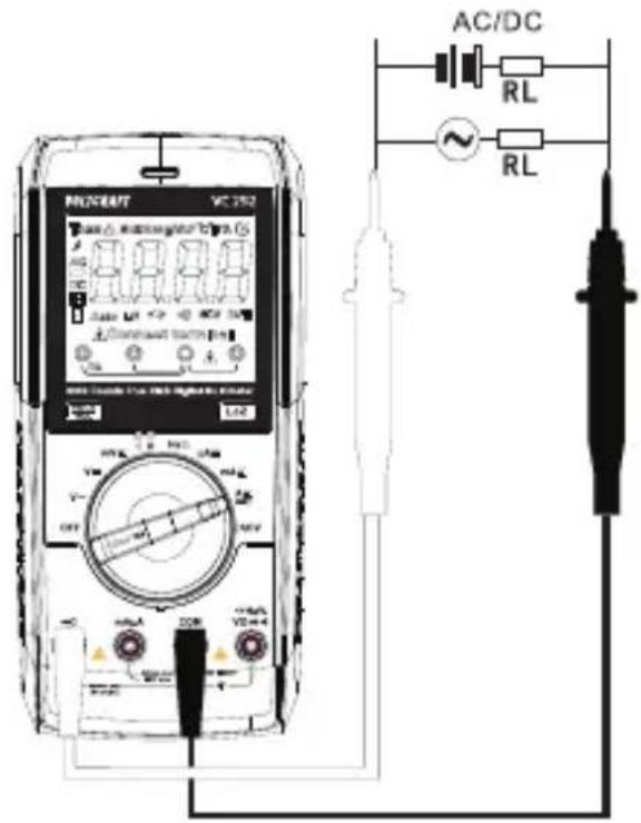
12.6 Measure mV/DC voltage ("mV")
Proceed as follows to measure direct voltages "mV/DC":
- Switch the DMM on and select the mV-measurement mode. "DC" and "mV" will appear on the display.
- Insert the red lead into the V socket and the black lead into the COM socket.
- Connect the two measuring probes in parallel to the object that you want to measure (e.g. battery or circuit).
→ The measurement will appear on the display.
- After taking a measurement, remove the leads from the measured object and switch the DMM off.
The “mV/DC” voltage measurement range has an resistance of ≥100 MΩ. This (almost entirely) prevents a load on the circuit.
12.7 LoZ voltage mode
LoZ mode allows you to measure DC and AC voltages with a low impedance (approx. 400 kΩ). In this mode, the multimeter lowers the internal resistance to prevent phantom voltage readings. As a result, the circuit is more heavily loaded than in the standard measuring mode.
-
In order to use LoZ measurement mode, press the LoZ button during voltage measurement. The measured impedance is reduced for as long as the button is pressed.
-
"LoZ" will appear on the display.

LoZ measurement mode may only be used up to a maximum voltage of 250 V. The duration of the LoZ measurement must be limited to a maximum of 3 s. This mode is not available in the mV measurement range.
After using LoZ mode, leave the multimeter for 1 minute before using it again.
12.8 Contactless clamp current measurement "A"

Never exceed the maximum permitted input values. Do not touch any circuits or circuit components if the circuit has voltages higher than AC 30 Vr.m.s, 42.4 V peak or DC 60 V. Danger of death!
The voltage in the measured circuit must not exceed 600 V.
Pay attention to the necessary safety information, regulations and protective measures for your own safety.
The “clamp current measurement” measurement range is a high-impedance range and can only be used with the “CLA60” clamp transformer. Direct measurement is not permissible.
Through a clamp transformer (current clamp), the DMM enables the measurement of direct and alternating currents up to 60 A. Measurement is carried out contactlessly using a fold-out clamp current sensor. For clamp measurement, the current circuit does not need to be disconnected.
The sensors in the current clamp detect the magnetic field created by current-carrying conductors. You can take measurements on insulated and uninsulated conductors. Always ensure that the conductor passes through the centre of the current clamp (pay attention to the arrow marks) and that the clamp is closed.
The clamp transformer can be used for direct and alternating current measurements. 10 mV per measured ampere is output at the output.
The measurement is indicated on the display in amperes. Conversion as with conventional adapters is not required.

Do not use the current clamp to surround more than one conductor. If the supply and return conductors (e.g. L and N) are measured, the currents will cancel each other out and no measurement will be displayed. If several supply conductors (e.g. L1 and L2) are measured, the currents will be added together.
natural_image
Pure electrical circuit lines without any symbols
natural_image
Diagram of a magnetic field experiment setup with a ring magnet and rotating coil, no text or symbols present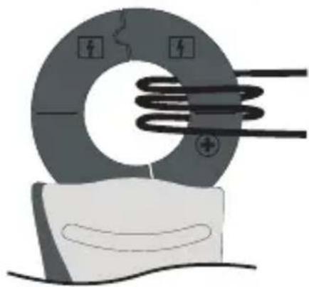
natural_image
Illustration of a solenoid with magnetic field lines and a magnified view of its surface (no text or symbols)At low currents, the conductor can be wound around one side of the current clamp to increase the total measured current. Divide the measured current by the number of coils. You will then receive the correct current value.

The slide switch of the clamp transformer also works as battery replacement indicator. If the switch flashes in the "ON" position or does not light up, the batteries must be replaced immediately, otherwise measurement errors may occur.
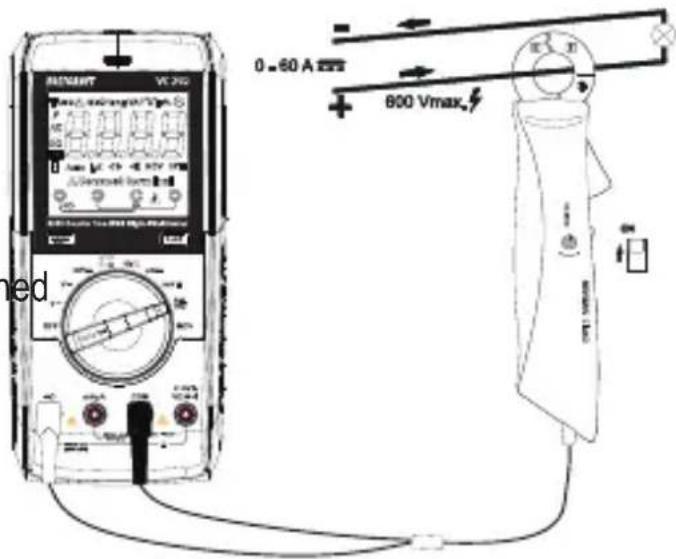
12.8.1 Measure alternating currents up to max. 60 A ---
- Switch the DMM on and select A mode. "A" and "DC" will be displayed.
- Insert the red test lead of the current clamp into the measurement socket "
of the DMM. Insert the black test lead into the COM measurement socket.
- Switch the current clamp on at the operating switch.
→ The current clamp is switch on in the ON switch position. The switch lights up red.
→ The OFF position is off.
- Set the display to zero before each DC measurement. To do
this, turn the “DC ZERO” rotary control with the clamp closed until the display is as close to zero as possible (<0.050 A). The current clamp is very sensitive thanks to the integrated hall sensor and should be re-calibrated after each opening of the current sensor.
→ It is possible that external influences will prevent the exact zero position from being set (e.g. 0.038 A etc.). In this case, the offset error remains linear throughout the measurement range and can be subtracted from the measurement. This will not impair the measurement.
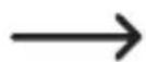
- To open the current clamp sensor, press the clamp opening lever and clamp the measurement adapter over the lead to be measured with the correct polarity.
→ Always ensure the correct polarity of the current clamp for direct current measurements. The polarity symbols are located on the front and back of the current clamp. The cable from the current source (+) must run from the front through the current clamp to the load.
- Surround the conductor that you want to measure and close the current clamp. Position the conductor in the middle between the two position symbols on the clamp. When surrounding a conductor, ensure that the clamp sensor is closed properly, otherwise, measurement errors may occur.
→ The measurement will appear on the display.
→ A minus “-” symbol in front of the measurement indicates that the current is flowing in the opposite direction (or that the test leads or current sensor are connected with the wrong polarity).
- After measuring, remove the clamp transformer from the measured object and switch both devices off.
12.8.2 Measure alternating currents up to max. 60 A \~
- Switch the DMM on and select A mode. "A" and "DC" will be displayed.
- Press SEL/☐ to switch to AC mode. "AC" and "TRMS" appear on the display.
→ The display is automatically
set to zero when the current clamp is closed in the alternating current measurement range. The rotary control has no function here. It may be that external influences (e.g. a strong magnetic field in the vicinity) prevent a precise zero position from being reached. In this case, the offset error remains linear throughout the measurement range and can be subtracted from the measurement. This will not impair the measurement.
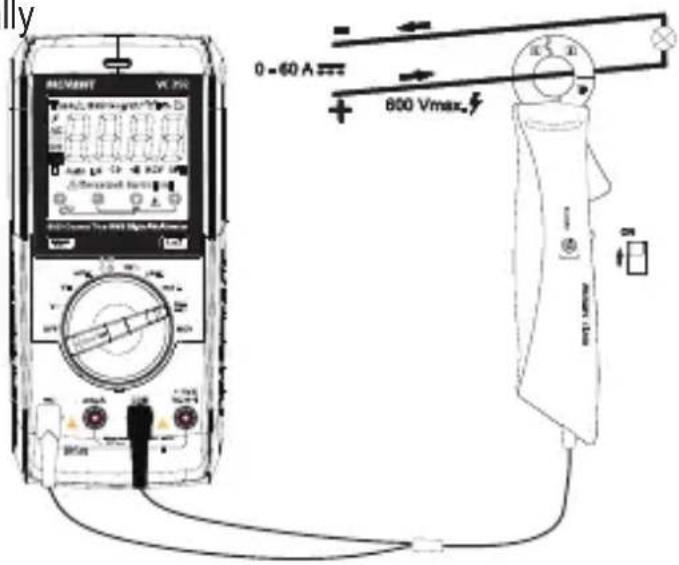
- Press the opening lever to open the current clamp. The current flow direction does not need to be considered in AC mode as an alternating field is present.
-
Surround the conductor that you want to measure and close the current clamp. Position the conductor in the middle between the two position symbols on the clamp.
→ The measured alternating current is indicated on the display. -
After measuring, remove the clamp transformer from the measured object and switch both devices off.
12.9 Contacted current measurement up to 600 mA

Never exceed the maximum permitted input values. Do not touch any circuits or circuit components if the circuit has voltages higher than AC 30 Vr.m.s, 42.4 V peak or DC 60 V. Danger of death!
The voltage in the measured circuit must not exceed 600 V.
Always start contacted current measurement with the highest measurement range and switch down to lower ranges if necessary. Before connecting the multimeter and before changing the measurement range, always de-energise the circuit. All current measurement ranges are provided with fuses and thus protected against overload.
Never measure currents above 600 mA in the mA/ A range as this will cause the PTC protection elements to trip.
The A/mA measurement input has a self-resetting PTC fuse, which means that you do not need to replace the fuse in the event of an overload.
Perform the current measurement in the mAμA measurement range as quickly as possible. Continuous measurements are to be avoided. The PTC technology heats the protective components in the measurement circuit with increasing current strength or measurement duration. Consequently, the internal resistance increases and the current flow is limited. Please take this into account when performing series of measurements.
An optical and acoustic alarm are triggered when the measurement range is exceeded.
If the PTC fuse has been triggered (steadily declining measurement indicator, "OL" or alarm), stop the measurement and switch the DMM off (OFF). Wait for approx. 5 minutes. The self-resetting fuse cools down and then functions again.
When the meter is being used for mA/ A measurement, but the meter is mistakenly connected to a high-energy high-voltage power supply, then the ceramic tube fuse will work and probably blow to protect the meter. In such case, the blown ceramic tube fuse is required to be replaced by a new one.
12.9.1 Measure direct currents (mA/μA)
- Switch the DMM on and select mA or A mode.
→ The table shows the different modes and potential measurement ranges. Select the measurement range and corresponding measurement sockets.
| Measurement mode | Measurement range | Measurement sockets |
| μA 0 - 6000 μA COM + mAμA | ||
| mA 6000 μA - 600 mA | COM + mAμA |
- Insert the red test lead into the mAμA measurement socket. Insert the black test lead into the COM measurement socket.
- Connect the two measuring probes (de-energised) in series to the object that you want to measure (e.g. battery or circuit). The electrical circuit must be disconnected before you connect the probes.
- Reconnect the circuit. The measurement will appear on the display.
- After measuring, disconnect the circuit and remove the test leads from the measured object. Switch the DMM off.
12.9.2 Measure alternating currents (mA/μA)
- Switch the DMM on and select mA or mode.
- Press SEL/ to switch to AC mode.
→ “AC” and “TRMS” appear on the display.
→ The table shows the different modes and potential measurement ranges. Select the measurement range and corresponding measurement sockets.
| Measurement mode | Measurement range | Measurement sockets |
| μA 0 - 6000 μA COM + | mAμA | |
| mA 6000 μA - 600 mA | COM + mAμA |
- Insert the red test lead into the mAμA measurement socket. Insert the black test lead into the COM measurement socket.
- Connect the two measuring probes (de-energised) in series to the object that you want to measure (e.g. generator, battery or circuit). The electrical circuit must be disconnected before you connect the probes.
- Reconnect the circuit. The measurement will appear on the display.
- After measuring, disconnect the circuit and remove the test leads from the measured object. Switch the DMM off.
12.10 Frequency measurement
The DMM can be used to measure the frequency of a signal voltage (supports frequencies from 10 Hz to 10 MHz). The maximum input is 20 Vrms. This mode is not suitable for taking measurements on mains voltages. Observe the input specifications in the technical data.
Proceed as follows to measure frequency:
- Switch the DMM on and select Hz mode. "Hz" will appear on the display.
- Insert the red test lead into the Hz measurement socket and the black test lead into the COM measurement socket.
- Connect the two measuring probes to the object that you want to measure (e.g. signal generator or circuit).
→ The frequency and corresponding unit will be displayed.
- After taking a measurement, remove the leads from the measured object and switch the DMM off.
12.11 Measurement of pulse duration in %
The DMM can be used to measure the ratio of the pulse duration of an alternating voltage signal's positive half wave as a percentage of the entire period. The maximum input is 20 Vrms. This mode is not suitable for taking measurements on mains voltages. Observe the input specifications in the technical data.
Proceed as follows to take a pulse frequency measurement:
- Switch the DMM on and select the Hz measurement range. "Hz" will appear on the display.
- Press the SEL/ button on the rotary control. “%” will appear on the display.
- Insert the red test lead into the Hz measurement socket and the black test lead into the COM measurement socket.
- Connect the two measuring probes to the object that you want to measure (e.g. signal generator or circuit).
→ The pulse duration of the positive half wave is shown as a percentage value on the display.
- After taking a measurement, remove the leads from the measured object and switch the DMM off.
12.12 Resistance measurement

Ensure that all objects that you want to measure (including circuit components, circuits and component parts) are disconnected and discharged.
Proceed as follows to measure the resistance:
- Switch the DMM on and select the measurement mode.
- Insert the red test lead into the measurement socket and the black test lead into the COM measurement socket.
- Check the test leads for continuity by connecting both measuring probes to one another. The multimeter should then show a resistance value of approx 0 - 0.5 Ω (inherent resistance of the test leads).
→ For low-impedance measurements of <600 Ω, hold down
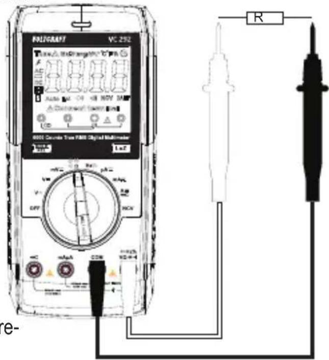
the REL button for approximately one second when the measuring probes are short circuited. This ensures that the inherent resistance of the test leads does not affect the resistance measurement. The display should show 0 Ω. Auto range is thereby disabled.
- Connect the measuring probes to the object that you want to measure. The measurement will be indicated on the display (provided that the object you are measuring is not highly resistive or disconnected). Wait until the display stabilises. This may take a few seconds for resistances greater than 1 MΩ.
→ "OL" (overload) indicates that the measurement range has been exceeded or that the circuit is broken.
- After taking a measurement, remove the leads from the measured object and switch the DMM off.
When taking a resistance measurement, ensure that the points that come into contact with the measuring probes are free from dirt, oil, solder and other impurities. These substances may distort the measurement.
The REL button only works when a measurement is displayed. It cannot be used when "OL" is displayed.
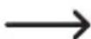
12.13 Diode test

Ensure that all objects that you want to measure (including circuit components, circuits and component parts) are disconnected and discharged.
-
Switch the DMM on and select the mode.
-
Press SEL/ 2x to switch to diode test mode.
→ The diode symbol and will appear on the display.
-
Press the button again to switch to the next mode.
-
Insert the red test lead into the measurement socket and the black test lead into the COM measurement socket.
-
Check the test leads for continuity by connecting both measur-
ing probes to one another. A value of approx. 0.000 V should be shown.
- Now connect the two measuring probes to the object to be measured (diode). The red test lead to the anode (+), the black test lead to the cathode (-).
→ The normal PN junction forward voltage will be shown in volts (V). “OL” indicates that the diode is reverse-biased or defective. Try taking the measurement again with the opposite polarity.
- After taking a measurement, remove the leads from the measured object and switch the DMM off.
12.14 Continuity test

Ensure that all objects that you want to measure (including circuit components, circuits and component parts) are disconnected and discharged.
- Switch the DMM on and select mode.
- Press the SEL/ button once to switch to the mode.
→ The continuity test symbol and the Ω symbol will appear on the display.
-
Press the SEL/butlon again to switch to the next mode.
-
Insert the red test lead into the measurement socket and the black test lead into the COM"measurement socket.
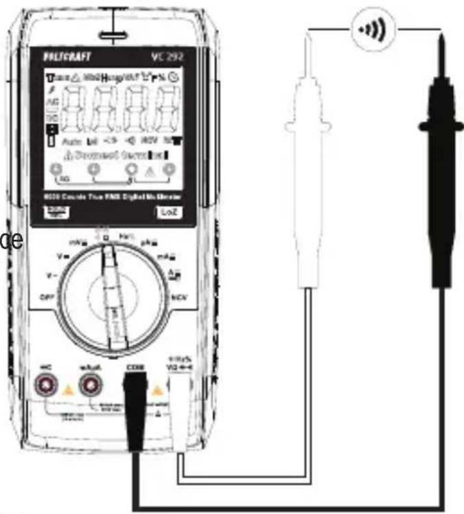
→ If the measured resistance is equal to or less than 10 Ω, the multimeter will beep to indicate continuity. There is no further beeping from >100 Ω. The continuity test measures resistances of up to 600 Ω.
→ “OL” (overload) indicates
that the measurement range has been exceeded or that the circuit is broken.
- After taking a measurement, remove the leads from the measured object and switch the DMM off.
12.15 Capacitance measurement

Ensure that all objects that you want to measure (including circuit components, circuits and component parts) are disconnected and discharged.
Always pay attention to the polarity when using electrolytic capacitors.

- Switch the DMM on and select the measurement range
- Press the SEL/ button 3x to switch to capacitance mode.
- Insert the red lead into the V socket and the black lead into the COM socket.
→ “nF” will appear on the display.
→ Due to the sensitive measuring input, the display may show a reading even with "open" test leads.
→ Press the REL button to measure small capacities (<600 nF). The indicator is then set to "0". Auto range is thereby disabled.
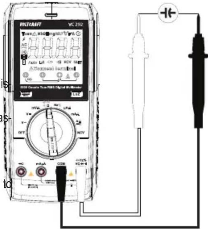
- Connect the two measuring probes (red = positive, black = negative) to the object that you want to measure (capacitor). The capacitance will be shown on the display after a few seconds. Wait until the display stabilises. This may take a few seconds for capacitances greater than 60 F .
→ “OL” (overload) indicates that the measurement range has been exceeded.
- After taking a measurement, remove the leads from the measured object and switch the DMM off.
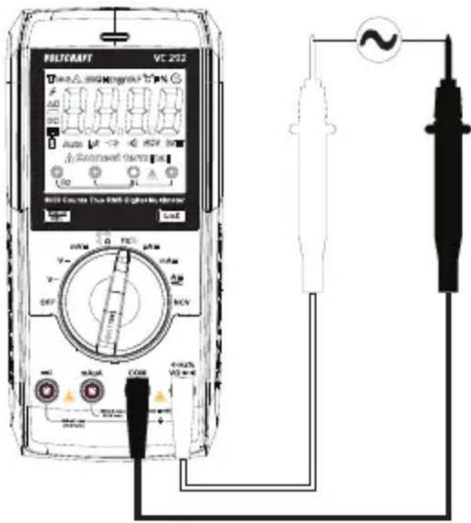
12.16 Non-contact AC voltage test "NCV"
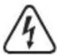
Make sure that all measuring sockets are unoccupied. Please remove all measuring leads and adapters from the measuring device.
This function only serves as an aid. Prior to performing work on these cables, you must perform contact measuring operations to check for the absence of voltage.
Test this function beforehand on a known AC voltage source.
- Set the function dial to NCV, "EF" and "NCV" will show on the display.
- Guide the non-contact voltage sensor area to the test location (max. 5 mm). For twisted cables, it is recommended to touch the cable with the end of non-contact voltage sensor.
→ If AC power is sensed, the tri-color indicator LED will light up and the buzzer will sound.
→ The higher the voltage, the higher the frequency at which the buzzer will beep.
→ The tri-color indicator LED will change from green to yellow to red as the voltage increases.
- When finished measuring, switch the power OFF.
13 Additional functions
You can use the function button to enable a range of different functions. The multimeter beeps each time you press the button.
13.1 SEL function
Some measurement modes have additional sub-modes. The sub-functions are in the rotation area marked grey. To switch to a sub-mode, press the SEL/≡ button briefly (<2 s). Press the SEL/≡ button again to switch to the next sub-mode.
13.2 Torch
Long press the SEL/ button to switch the torch ON/OFF.
13.3 REL function
The REL function allows you to take a reference measurement to avoid possible line losses (e.g. during resistance measurements). For this purpose, the current indicated value is set to zero. A new reference value is set.
- To enable this function, press and hold the REL button for approx. 2 s. The display shows “Δ” and the measurement indicator is set to zero. The automatic measurement range selection thereby disabled.
- To disable this function, change the measurement mode or press and hold the REL button for approx. 2 s.

The REL function is not enabled in the following measurement modes: Frequency, diode test and continuity test.
The REL button only works when a measurement is displayed. It cannot be used when "OL" is displayed.
13.4 HOLD function
This feature freezes the current reading on the display so that you can record it for future reference.

If you test live wires, ensure that this function is disabled before the measurement starts. Otherwise, a false measuring result is simulated!
- Press the HOLD button to enable this function, H will be displayed.
- To disable the hold feature, press the HOLD button or change the measurement mode.
13.5 Auto power-off function
The DMM switches off automatically after 15 minutes if no buttons are pressed. This function saves battery power and extends the service life. The symbol will be displayed when the automatic shut-off feature is enabled.
The DMM will beep several times approximately 1 minute before it turns off. If the the REL/HOLD or SEL/☐ button is pressed during this time to cancel shut-off, the next shut-off signal is sounded after a further 15 minutes. You will hear a long beep when the multimeter switches off.
To switch the DMM back on, move the rotary control to the "OFF" position or press the REL/HOLD or SEL/ button.
The automatic shut-off feature can be disabled manually.
Follow the steps below to disable the automatic power-off feature:
- Switch the multimeter off (OFF).
- Hold down the SEL/☐ button and switch the DMM on using the rotary control. The “” symbol will no longer be visible on the display. The automatic shut-off feature will remain disabled until the multimeter is switched off using the rotary control.

The CLA60 clamp transformer does not have an automatic shut-off function. Always switch this off at the operating switch after measuring.
14 Cleaning and maintenance
14.1 General information
The multimeter should be calibrated once a year to ensure that measurements remain accurate.
The multimeter does not need to be serviced (apart from occasional cleaning and battery/fuse replacements).
Refer to the following sections for instructions on how to change the fuse and battery.

Regularly check the device and test leads for signs of damage.
14.2 Cleaning
Always observe the following safety instructions before cleaning the device:

Opening covers on the product or removing parts that cannot be removed by hand may expose voltage-carrying components.
Before cleaning or servicing the multimeter, disconnect all cables from the multimeter and measured objects, and then switch the multimeter off.
Do not use abrasive detergents, petrol, alcohol or other similar chemicals to clean the device. These may corrode the surface of the multimeter. In addition, the vapours emitted by these substances are explosive and harmful to your health. Do not use sharp-edged tools, screwdrivers or metal brushes to clean the device.
Use a clean, damp, lint-free and antistatic cloth to clean the multimeter, display and test leads. Allow the multimeter to dry out completely before using it again.
14.3 Opening the battery/fuse compartment
The battery/fuse compartment cannot be opened when the leads are connected to the terminals.
All terminals are automatically locked when the battery/fuse compartment is opened to prevent leads from being inserted.
Follow the steps below to open the battery/fuse compartment:
- Disconnect all test leads from the multimeter and switch the multimeter off.
- Loosen and remove the battery compartment screw on the back of the multimeter.
- Collapse the fold-out stand and slide the battery/fuse compartment cover off the bottom of the multimeter.
→ You should now be able to access the fuses and the battery.
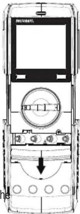
- Repeat the above steps in the reverse order to replace the battery/fuse compartment cover, and then screw it in place.
→ The multimeter is now ready to use.
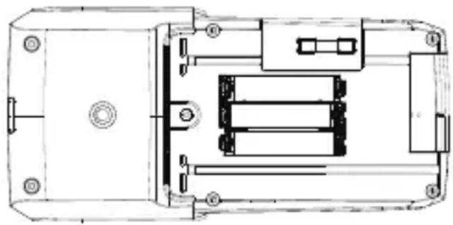
14.4 Inserting/changing the battery
- Disconnect the multimeter and test leads from all circuits, and then disconnect all test leads from the multimeter.
- Switch off the multimeter.
- Remove the battery/fuse compartment cover (see "Opening the battery/fuse compartment").
- Insert new batteries with the same specifications.
→ Pay attention to the polarity markings in the battery compartment.
- Carefully replace the battery/fuse compartment cover.

Never use the multimeter when the battery/fuse compartment is open. !RISK OF FATAL INJURY!
Do not leave empty batteries in the device. Even leakproof batteries may corrode and destroy the device or release chemicals that are detrimental to your health.
Do not leave batteries unattended, as they may be swallowed by children or pets. Seek immediate medical attention if a battery is swallowed.
If you do not plan to use the multimeter for an extended period, remove the battery to prevent it from leaking.
Leaking or damaged batteries may cause acid burns if they come into contact with your skin. Always use protective gloves when handling leaking or damaged batteries.
Batteries must not be short-circuited or thrown into open flames!
Do not recharge or disassemble non-rechargeable batteries, as this may cause an explosion.
natural_image
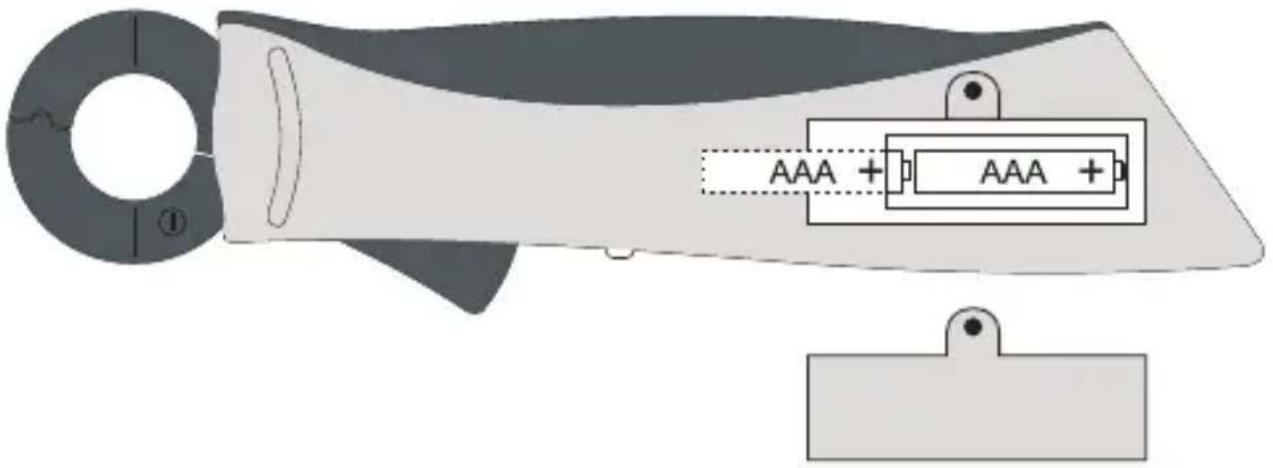
Technical line drawing of a mechanical housing or enclosure with internal components (no text or symbols)Insert/replace the batteries on the CLA60 clamp transformer:
The clamp transformer requires two 1.5 V micro batteries (e.g. AAA, LR3). On initial operation or if the operating light on the slide switch flashes or no longer lights up, insert two new, fully charged batteries.
- Disconnect the measurement adapter from the measured object and the connected test leads from your multimeter.
- Switch the adapter OFF.
- Open the battery compartment on the rear with a suitable screwdriver and remove the battery compartment cover.
- Replace the used batteries with new ones of the same type. Insert the new batteries into the battery compartment with the correct polarity. Look for the polarity signs in the battery compartment.
- Carefully replace the battery/fuse compartment cover.
15 Disposal
15.1 Product
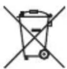
This symbol must appear on any electrical and electronic equipment placed on the EU market. This symbol indicates that this device should not be disposed of as unsorted municipal waste at the end of its service life.
Owners of WEEE (Waste from Electrical and Electronic Equipment) shall dispose of it separately from unsorted municipal waste. Spent batteries and accumulators, which are not enclosed by the WEEE, as well as lamps that can be removed from the WEEE in a non-destructive manner, must be removed by end users from the WEEE in a non-destructive manner before it is handed over to a collection point.
Distributors of electrical and electronic equipment are legally obliged to provide free take-back of waste. Conrad provides the following return options free of charge (more details on our website):
in our Conrad offices
at the Conrad collection points
at the collection points of public waste management authorities or the collection points set up by manufacturers or distributors within the meaning of the ElektroG
End users are responsible for deleting personal data from the WEEE to be disposed of.
It should be noted that different obligations about the return or recycling of WEEE may apply in countries outside of Germany.
15.2 (Rechargeable) batteries
Remove batteries/rechargeable batteries, if any, and dispose of them separately from the product. According to the Battery Directive, end users are legally obliged to return all spent batteries/rechargeable batteries; they must not be disposed of in the normal household waste.
Batteries/rechargeable batteries containing hazardous substances are labelled with this symbol to indicate that disposal in household waste is forbidden. The abbreviations for heavy metals in batteries are: Cd = Cadmium, Hg = Mercury, Pb = Lead (name on (rechargeable) batteries, e.g. below the trash icon on the left).
Used (rechargeable) batteries can be returned to collection points in your municipality, our stores or wherever (rechargeable) batteries are sold. You thus fulfil your statutory obligations and contribute to environmental protection.
Batteries/rechargeable batteries that are disposed of should be protected against short circuit and their exposed terminals should be covered completely with insulating tape before disposal. Even empty batteries/rechargeable batteries can contain residual energy that may cause them to swell, burst, catch fire or explode in the event of a short circuit.
16 Troubleshooting
The multimeter was designed using the latest technology and is safe to use. However, problems and malfunctions may still occur.
This section tells you how to troubleshoot possible faults:

Always observe the safety information in these instructions.
| Problem Possible cause | Suggested solution | |
| The multimeter does not work. | Is the battery flat? Check | the battery level and replace if necessary. |
| The measured value does not change. | Have you selected the wrong measurement mode (AC/DC)? | Check the display (AC/DC) and select another mode if necessary. |
| Did you use the wrong measurement sockets? | Check that the test leads are connected to the correct terminals. | |
| Is the hold function enabled? | Disable the hold function. | |
| No measurement possible with the current clamp | Is the current clamp switched on? | Check the operating indicator.Replace the batteries. |
| Was the wrong mode (AC/DC) selected on the multimeter? | Check the settings on the multimeter. | |
| The multimeter cannot take measurements in the mA/μA range. | The F2 fuse is blown. Replace the F2 fuse with a new one. | |

Any repair work other than that described above must be carried out by an authorized technician. If you have questions about the multimeter, please contact our technical support team.
17 Technical data
17.1 Multimeter VC292
Display......6000 Counts (digits)
Measuring rate....approx. 2 - 3 measurements/second
AC measurement method......True RMS, AC-coupled
Test lead length ....approx. 90 cm
Measuring impedance ≥10 M (mV: ≥100 M )
Measurement socket clearance....19 mm (COM-V)
Low battery indicator ....Battery voltage <3.6 ±0.2 V
"Dangerous voltage" indicator ....≥30 V/AC-DC
"Range exceeded" alarm....≥600 V/AC-DC,>60 A/AC-DC
“OL” (overload) alarm ≥ 610 V/AC-DC, ≥ 60, 10 A/AC-DC or measurement >6000 counts
Automatic shut-off .... after approx.15 minutes (can be manually disabled)
Current consumption (auto off)....<50 μA
Operating voltage 3x AAA 1.5 V batteries
Operating conditions....0 to +40 °C (<75% RH)
Operating altitude .... max. 2000 m above sea level
Storage temperature....-10 °C to +50 °C
Weight ....approx. 375 g
Dimensions (L x W x H)....190 x 90 x 43 mm
Measuring category....CAT III 600 V
Pollution degree....2
Operating environment....Indoor use
Safety regulations ....EN 61010-1 and EN61010-2-033
F2 FUSE....Φ5×20 mm, FF 2.5 A, H 700 V, Breaking capacity: min 300 A
17.2 CLA60 clamp transformer
Clamp opening 25 mm
Maximum conductor diameter ....20 mm
Measurement function....DC, AC True RMS
Output....10 mV/A
Test lead length ....approx. 120 cm
Power supply voltage ....2x AAA 1.5 V batteries
Operating conditions....0 to +40 °C (<75% RH)
Operating altitude .... max. 2000 m above sea level
Storage temperature....-10 °C to +50 °C
Weight ....approx. 184 g
Dimensions (L x W x H)....195 x 50 x 29 mm
Measuring category....CAT III 600 V
Pollution degree....2
Safety regulations ......meets EN 61010-1
Measuring tolerances
Accuracy in ± (% of reading + display error in counts (= number of smallest points)). These accuracy readings are valid for one year at a temperature of +23 °C ( ± 5 °C) and a relative humidity of less than 75 % (non-condensing). If the multimeter is used outside of this temperature range, use the following coefficient to calculate the accuracy. +0.1 x (specified accuracy)/1 °C.
The accuracy of measurements may be affected when the multimeter is used in a high-frequency electromagnetic field.
Direct voltage (V/DC)
| Range Resolution Accuracy | ||
| 60.00 mV* 0.01 mV ±(1.2% + 8) | ||
| 600.0 mV* 0.1 mV ±(0.9% + 8) | ||
| 6.000 V 0.001 V | ±(0.8% + 4) | |
| 60.00 V 0.01 V | ||
| 600.0 V 0.1 V | ||
| *Only available in “mV” modeSpecified measurement range: 5 - 100% of the measurement range600 V overload protection; Impedance: 10 MΩ (mV: ≥100 MΩ)The multimeter may display ≤5 counts if a measurement input is short-circuited. | ||
Direct voltage (V/DC) LoZ
| Range Resolution Accuracy | ||
| 6.000 V 0.001 V | ±(1.7% + 7)60.00 V 0.01 V | |
| 600.0 V 0.1 V | ||
| Specified measurement range: 5 - 100% of the measurement range600 V overload protection; Impedance: 400 kΩ (max. 250 V, 3 secs)The multimeter may display ≤5 counts if a measurement input is short-circuited.After using the LoZ feature, leave the multimeter for 1 minute before using it again. | ||
Alternating voltage (V/AC)
| Range Resolution | Accuracy | |
| 60.00 mV* 0.01 mV | ±(1.4% + 5) | |
| 600.0 mV* 0.1 mV | ||
| 6.000 V 0.001 V | ±(1.3% + 4) | |
| 60.00 V 0.01 V | ||
| 600.0 V 0.1 V | ||
| *Only available in “mV” modeSpecified measurement range: 5 - 100% of the measurement rangeFrequency range: 45 - 400 Hz; 600 V overload protection; Impedance: 10 MΩ (mV: ≤100 MΩ)The multimeter may display 5 counts if a measurement input is short-circuited. | ||
| TrueRMS peak (Crest Factor (CF)) ≤3 CF to 600 VTrueRMS peak for non-sinusoidal signals plus toleranceCF >1.0 - 2.0 + 3%CF >2.0 - 2.5 + 5%CF >2.5 - 3.0 + 7% | ||
Alternating voltage (V/AC) LoZ
| Range Resolution | Accuracy | |
| 6.000 V 0.001 V | ± (2.2% + 7)60.00 V 0.01 V | |
| 600.0 V 0.1 V | ||
| Specified measurement range: 5 - 100% of the measurement rangeFrequency range: 45 - 400 Hz; 600 V overload protection; Impedance: 400 kΩ (max. 250 V, 3 secs)The multimeter may display 5 counts if a measurement input is short-circuited.After using the LoZ feature, leave the multimeter for 1 minute before using it again. | ||
| TrueRMS peak (Crest Factor (CF)) ≤ 3 CF to 600 VTrueRMS peak for non-sinusoidal signals plus toleranceCF >1.0 - 2.0 + 3%CF >2.0 - 2.5 + 5%CF >2.5 - 3.0 + 7% | ||
Direct current (A/DC)
| Range Resolution Accuracy | |
| 600.0 μA 0.1 μA | |
| 6000 μA 1 μA | |
| 60.00 mA 0.01 mA | |
| 600.0 mA 0.1 mA | |
| 6.000 A 0.001 A ±(3.2% + 27) | |
| 60.00 A 0.01 A ±(3.2% + 5) |
600 V overload protection
Fuses: A/mA = 2x 0.55 A/240 V resettable, 1x F2 2.5 A/700 V ceramic, internal resistance approx. <10
60 A transformer input: 10 mV/A, max. 600 mV, overload protection by PTC
Specified measurement range with a clamp transformer: 0.6 - 60 A
The multimeter may display 3 counts when a measurement input is open
Alternating current (A/AC)
| Range Resolution Accuracy | ||
| 600.0 μA 0.1 μA | ±(1.3% + 4) | |
| 6000 μA 1 μA | ||
| 60.00 mA 0.01 mA | ||
| 600.0 mA 0.1 mA | ||
| 6.000 A 0.001 A ±(3.2% + 27) | ||
| 60.00 A 0.01 A ±(3.2% + 5) | ||
| Overload protection 600 V; frequency range 45 - 400 HzFuses: μA/mA = 2x 0.55 A/240 V resettable, 1x F2 2.5 A/700 V ceramic, internal resistance approx. <10 Ω60 A transformer input: 10 mV/A, max. 600 mV, overload protection by PTCSpecified measurement range mA/μA: 5 - 100% of the measurement rangeSpecified measurement range with a clamp transformer: 0.6 - 60 AThe multimeter may display 3 counts when a measurement input is open | ||
| TrueRMS peak (Crest Factor (CF)) ≤3 CF over the entire rangeTrueRMS peak for non-sinusoidal signals plus toleranceCF >1.0 - 2.0 + 3%CF >2.0 - 2.5 + 5%CF >2.5 - 3.0 + 7% | ||
Resistance
| Range Resolution Accuracy | ||
| 600.0 Ω* 0.1 Ω ±(1.3% + 4) | ||
| 6.000 KΩ 0.001 KΩ | ±(1.2% + 7)60.00 KΩ 0.01 KΩ | |
| 600.0 KΩ 0.1 KΩ | ||
| 6.000 MΩ 0.001 MΩ ±(1.5% + 4) | ||
| 60.00 MΩ 0.01 MΩ ±(2.7% + 7) | ||
| 600 V overload protectionMeasurement voltage: Approx. 1.0 V, measurement current approx. 0.7 mA*Accuracy for measurement range ≤600 Ω was calculated after deducting lead resistance from the REL function | ||
Capacitance
| Range Resolution Accuracy | ||
| 6.000 nF* 0.001 nF ±(4.4% + 9) | ||
| 60.00 nF* 0.01 nF ±(3.2% + 9) | ||
| 600.0 nF* 0.1 nF | ±(3.2% + 5) | |
| 6.000 μF 0.001 μF | ||
| 60.00 μF 0.01 μF | ||
| 600.0 μF 0.1 μF | ||
| 6.000 mF 0.001 mF | ±(4.4% + 5) | |
| 60.00 mF 0.01 mF | ±(7.0% + 5) | |
| 600 V overload protection*Accuracy for measurement range ≤600 nF only applies when the REL function is used | ||
Frequency "Hz" (electronic)
| Range Resolution Accuracy | ||
| ≤9.999 Hz* 0.001 Hz Not specified | ||
| 10.00 Hz - 99.99 Hz 0.01 Hz | ±(0.2% + 7) | |
| 100.0 Hz - 999.9 Hz 0.1 Hz | ||
| 1.000 kHz - 9.999 kHz 0.001 kHz | ||
| 10.00 kHz - 99.99 kHz 0.01 kHz | ||
| 100.0 kHz - 999.9 kHz 0.1 kHz | ||
| 1.000 MHz - 9.999 MHz 0.001 MHz | ||
| >10.00 MHz* 0.01 MHz Not specified | ||
| *The specified frequency range is 10.00 Hz - 10 MHzSignal level (without direct voltage component):≤100 kHz: 200 mVrms - 20 Vrms>100 kHz to 1 MHz: 600 mVrms - 20 Vrms>1 MHz ~ 5 MHz: 500mVrms - 20Vrms>5 MHz ~ 10MHz: 900 mVrms - 20 Vrms600 V overload protection | ||
Pulse width / pulse ratio (duty cycle)
| Range Resolution Accuracy | ||
| 0.1% - 99.9% 0.1% ±(2.3%) | ||
| Overload protection: 600 VSignal level (without direct voltage component):≤100 kHz: 1 mVrms - 20 VrmsFrequency range pulse width: ≤100 kHz | ||
Diode test
| Test voltage Resolution | |
| Approx. 3.0 V/DC 0.001 V | |
| Overload protection: 600 V; Test voltage: 2 mA typ. | |
Acoustic continuity tester
| Measurement range Resolution | |
| 600 Ω 0.1 Ω | |
| ≤10 Ω continuous tone; ≥100 Ω no toneOverload protection: 600 VTest voltage approx. 1 VTest current <1.5 mA | |

Never exceed the maximum permitted input values. Never touch circuits or parts of circuits when they may contain voltages greater than AC 30Vr.m.s, 42.4Vpeak or DC 60V! Danger of death!
France (email): technique@conrad-france.fr
natural_image
Pure electrical circuit lines without any symbols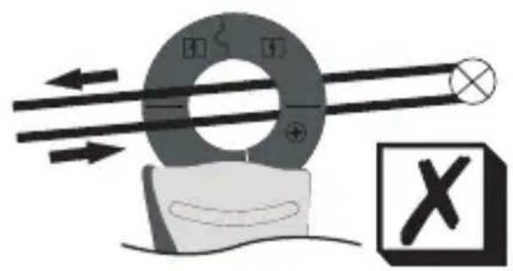
natural_image
Diagram of a magnetic field experiment setup with a ring magnet and rotating coil, showing magnetic field direction (no text or labels)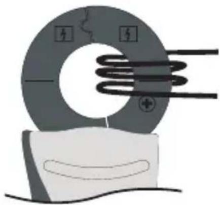
natural_image
Illustration of a solenoid with magnetic field lines and a magnified view of its surface (no text or symbols)natural_image
Top-down schematic of a mobile phone casing showing front panel, screen, and control panel (no text or symbols)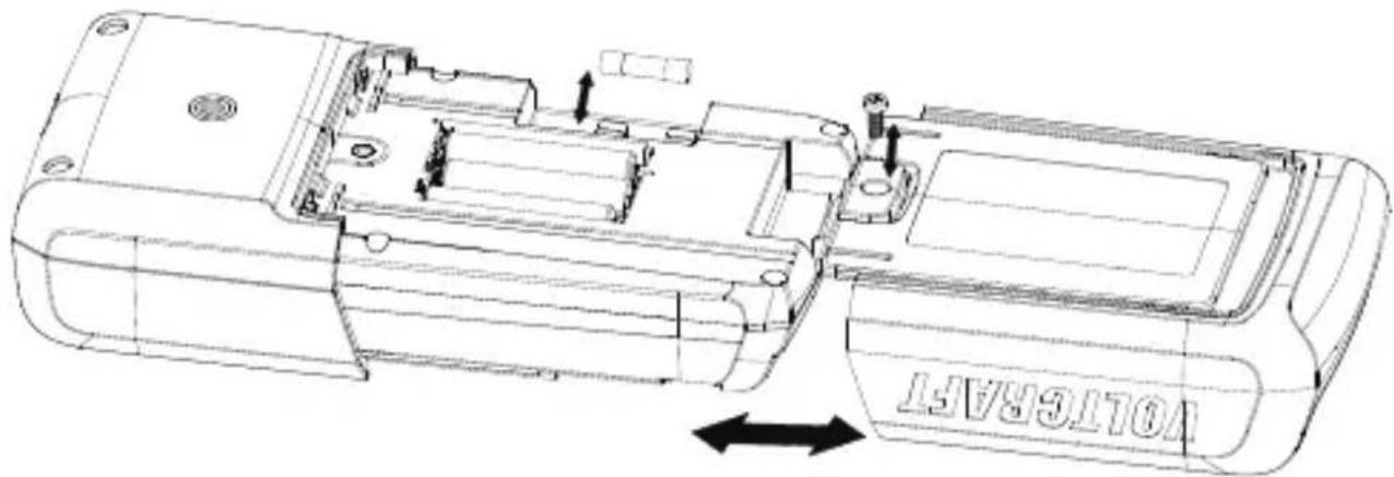
natural_image
Technical line drawing of a mechanical housing or enclosure with internal components and mounting holes (no text or symbols)Dimensions (L x W x H)....190 x 90 x 43 mm
Dimensions (L x W x H)....195 x 50 x 29 mm
Tension continue (V/CC)
Tension continue (V/CC) LoZ
Tension alternative (V/CA)
Tension alternative LoZ (V/CA)
Courant continu (A/CC)
natural_image
Pure electrical circuit lines without any symbols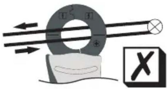
natural_image
Diagram of a magnetic circuit with rotating coil, magnetic field lines, and a cross symbol (no text or labels)
natural_image
Illustration of a solenoid with magnetic field lines and a magnified view of its surface (no text or symbols)12.9.2 Wisselstroom meten (mA/μA)
- Schakel de DMM in en selecteer de modus mA of μ.
- Druk op SEL/ om de AC-modus te openen.
12.10 Frequentiemeting
natural_image
Technical line drawing of a mechanical or electronic component with internal compartments and mounting holes (no text or symbols)De batterijen in de CLA60 stroomtang installeren/vervangen:
Tangopening....25 mm
Maximale geleiderdiameter ....20 mm
- Symbol-Erklärung
- Introduction
- Delivery content
- Up-to-date operating instructions
- Description of symbols
- CAT II
- CAT III
- CAT IV
- Intended use
- Safety instructions
- (Rechargeable) batteries
- Connected devices
- LED light
- Product description
- Product overview
- Multimeter
- Clamp
- Control dial
- Display elements and symbols
- Elements
- Symbols
- Taking measurements
- Switching the multimeter on and off Multimeter
- Clamp transformer
- Incorrect measurement socket warning
- Measure AC voltage "V\~
- Measure mV/AC voltage "mV"\~
- Measure DC voltage ("V=")
- Measure mV/DC voltage ("mV")
- LoZ voltage mode
- Contactless clamp current measurement "A"
- Measure alternating currents up to max. 60 A ---
- Measure alternating currents up to max. 60 A \~
- Contacted current measurement up to 600 mA
- Measure direct currents (mA/μA)
- Measure alternating currents (mA/μA)
- Frequency measurement
- Measurement of pulse duration in %
- Resistance measurement
- Diode test
- Continuity test
- Capacitance measurement
- Non-contact AC voltage test "NCV"
- Additional functions
- SEL function
- Torch
- REL function
- HOLD function
- Auto power-off function
- Cleaning and maintenance
- General information
- Cleaning
- Opening the battery/fuse compartment
- Inserting/changing the battery
- Insert/replace the batteries on the CLA60 clamp transformer:
- Disposal
- Product
- (Rechargeable) batteries
- Troubleshooting
- Technical data
- Multimeter VC292
- CLA60 clamp transformer
- Measuring tolerances
- Diode test
- Acoustic continuity tester
- Wisselstroom meten (mA/μA)
- Frequentiemeting
- De batterijen in de CLA60 stroomtang installeren/vervangen:
Brand : VOLTCRAFT
Model : VC292
Category : Multimeter