461825 - Odometer Extech - Free user manual and instructions
Find the device manual for free 461825 Extech in PDF.

| Product Type | Digital Wheel Odometer |
| Brand | Extech |
| Model | 461825 |
| Measurement Range | 0 to 99999.9 meters / feet |
| Resolution | 0.1 m (0.1 ft) |
| Accuracy | ±0.5% of reading |
| Measurement Units | Meters, feet, yards (depending on model) |
| Display | 6-digit LCD |
| Power Supply | 1 x 9V battery (included) |
| Battery Life | Approximately 100 hours of continuous use |
| Dimensions | 120 x 70 x 50 mm (excluding wheel) |
| Wheel Diameter | 160 mm |
| Weight | 320 g (with battery) |
| Housing Material | ABS plastic |
| Main Functions | Simple distance measurement, zero reset, last measurement memory |
| Maintenance and Cleaning | Clean with a damp cloth, do not use solvents |
| Safety | Indoor/outdoor use, avoid violent shocks |
| Available Spare Parts | 9V battery, replacement wheel |
| Warranty | 1 year (except sensors and cables: 6 months) |
| Certification | ISO 9001 |
Frequently Asked Questions - 461825 Extech
User questions about 461825 Extech
0 question about this device. Answer the ones you know or ask your own.
Ask a new question about this device
Download the instructions for your Odometer in PDF format for free! Find your manual 461825 - Extech and take your electronic device back in hand. On this page are published all the documents necessary for the use of your device. 461825 by Extech.
USER MANUAL 461825 Extech
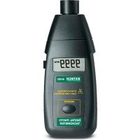
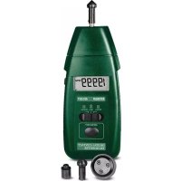
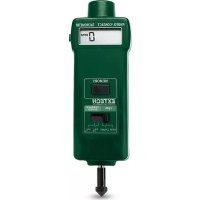
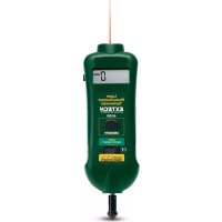
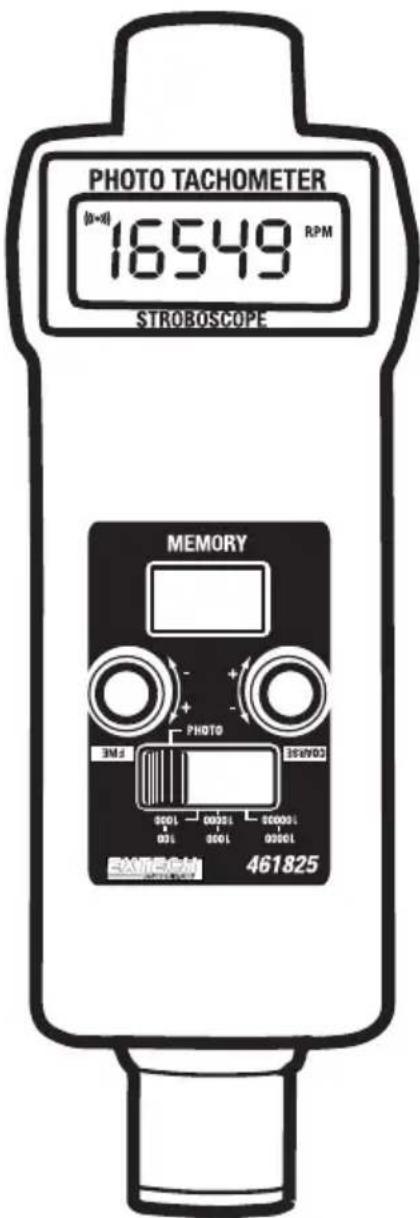
Combination Photo-Tachometer Stroboscope
Model 461825
Introduction
Congratulations on your purchase of Extech's Combination Photo-Tachometer/Stroboscope. This device is shipped fully tested and calibrated and, with proper use, will provide years of reliable service. Please visit our website (www.extech.com) to check for the latest version of this User Guide, Product Updates, and Customer Support.
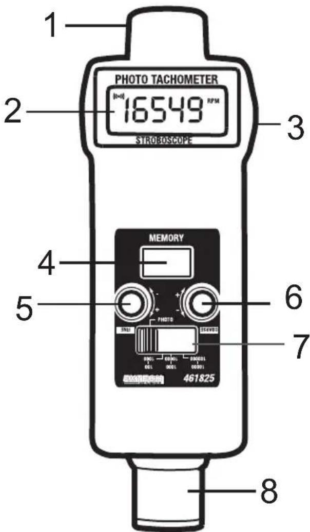
Meter Description
- Tachometer Light Source
- LCD Display
- Measure trigger button
- Memory Recall button
- FINE adjust knob
- COARSE adjust knob
- Range/Function select switch
- Stroboscope flash tube
Note: Battery compartment is on rear of meter
Disposal: Follow the valid legal stipulations in respect of the disposal of the device at the end of its lifecycle
STROBOSCOPE MEASUREMENT PROCEDURE
Select the Stroboscope Function and Range using the Range/Function Select Switch. The switch has four positions, three of which are stroboscope-dedicated with white range numbers. The fourth position is Photo-Tachometer dedicated and is labeled as such.
Speed Measurements.
- Remove power to the moving object under test and affix a target mark on the area to be measured.
- Apply power to the moving object and press the stroboscope's Measure Trigger Button.
- Aim the Stroboscope light beam toward the marked area on the object under test.
- Use the FINE and COARSE adjust knobs to synchronize or "stop" the motion of the object's mark. A single stationary image of the mark provides actual speed measurement data.
NOTE: Care must be taken to ensure that the mark is providing a 1:1 measurement. This is done by checking that there is only one mark and not two, four, or more stationary marks on the object under test. Two or more stopped marks indicate "harmonic" measurements (2:1, 3:1, 4:1, etc.) which provide a doubling, tripling, or quadrupling of the actual speed. A useful method of avoiding harmonic measurements is to adjust the FINE/COARSE knobs until two images (marks) appear and then lower the flash rate (via COARSE/FINE knobs) until a single, stationary image appears. This is the actual speed.
Inspecting a moving object
Measure the speed of a moving object as described above and move the FINE adjust knob alternately higher and lower to visually inspect all areas of the device.
PHOTO-TACHOMETER MEASUREMENT PROCEDURE
- Select the Photo-Tachometer function by moving the Range/Function select switch to the PHOTO position.
- Affix a small piece (approx. 0.5") of supplied reflective tape to the object under test.
- Press the meter's Measurement Trigger button and align the Photo-Tachometer light source with the reflective tape mark on the moving object.
- Wait until the Monitor Indicator appears in the upper left hand corner of the LCD indicating that synchronization has occurred.
- Release the Measure Trigger button only after the reading has stabilized (approx. 2 seconds).
NOTE: To obtain better accuracy for low RPM measurements (less than 50 RPM) use more than one piece of reflective tape. Divide the meter reading by the number of reflective tape pieces for accurate measurement data.
MEMORY RECORD AND RECALL
The 461825 can record Maximum, Minimum, and Last Reading for the period of time during which the Measure Trigger button is held. These stored values can then be read directly on the meter's display. The memory will automatically erase after approximately 10 seconds of meter inactivity. Access the memory data immediately after the measurements.
- Follow the instructions for normal operation.
- Release the Measurement Trigger button.
- Immediately press the Memory Recall button once to display the Last Reading taken during the measurement period. 'LA' will alternately display with the data reading to indicate 'Last Reading'.
- Release and press the Memory Recall button again to display the Maximum reading taken during the measurement period. 'UP' will alternately appear with the data reading to indicate the Maximum reading.
- Release and press the Memory Recall button again to display the Minimum reading taken during the 30 second test period. 'dn' will alternately appear with the data reading to indicate the Minimum reading.
Specifications
General Specifications
| Circuit Custom LSI | microprocessor based design |
| Display Reversible, | 0.4" (10mm) 5-digit (99999 count) LCD display |
| Measurement units | RPM (revolutions or rotations per minute) |
| Memory Recall Records/Recalls Max/Min/Last readings with memory push-button | |
| Operating Temperature | 32 to 122°F (0 to 50°C) |
| Operating Humidity | < 80% RH |
| Power Supply Four | 1.5V 'AA" batteries (UM-3 or equivalent) |
| Weight 0.48 lbs. | (216g) meter only |
| Dimensions 8.2 | x 2.8 x 1.9" (207 x 72 x 48mm) |
| Accessories Reflective tape and carrying case | |
Electrical Specifications
| Measurement Range 5 to 99,999 RPM for the Tachometer100 to 100,000 FPM/RPM for the Stroboscope | |
| Resolution 0.1 RPM (<1000 RPM) and 1 RPM (>1000 RPM) | |
| Accuracy ± (0.1% + 2 digits) | |
| Sampling Time 1 second (>60 RPM) | |
| Photo Tachometer detection distance | 2 to 6" (50 to 150mm) typicalNote: Detection distances up to 12" (300mm) are possible depending upon ambient light |
| Stroboscopic Flash rate 100 to 100 | 0,000 FPM (flashes per minute) |
| Stroboscopic Flash adjust range | Range A: 100 to 1,000 FPMRange B: 1000 to 10,000 FPMRange C: 10,000 to 100,000 FPM |
| Stroboscopic Flash tube type | High efficiency LED lamp |
| Stroboscopic Flash duration | 60 to 1000 microseconds (approx. 16% of period) |
| Stroboscopic Flash Color | Orange |
Warranty
FLIR Systems, Inc. warrants this Extech Instruments brand device to be free of defects in parts and workmanship for one year from date of shipment (a six month limited warranty applies to sensors and cables). If it should become necessary to return the instrument for service during or beyond the warranty period, contact the Customer Service Department for authorization. Visit the website www.extech.com for contact information. A Return Authorization (RA) number must be issued before any product is returned. The sender is responsible for shipping charges, freight, insurance and proper packaging to prevent damage in transit. This warranty does not apply to defects resulting from action of the user such as misuse, improper wiring, operation outside of specification, improper maintenance or repair, or unauthorized modification. FLIR Systems, Inc. specifically disclaims any implied warranties or merchantability or fitness for a specific purpose and will not be liable for any direct, indirect, incidental or consequential damages. FLIR's total liability is limited to repair or replacement of the product. The warranty set forth above is inclusive and no other warranty, whether written or oral, is expressed or implied.
Calibration, Repair, and Customer Care Services
FLIR Systems, Inc. offers repair and calibration services for the Extech Instruments products we sell. NIST certification for most products is also provided. Call the Customer Service Department for information on calibration services available for this product. Annual calibrations should be performed to verify meter performance and accuracy. Technical support and general customer service is also provided, refer to the contact information provided below.
Support Lines: U.S. (877) 439-8324; International: +1 (603) 324-7800
Technical Support: Option 3; E-mail: support@extech.com
Repair & Returns: Option 4; E-mail: repair@extech.com
Product specifications are subject to change without notice
Please visit our website for the most up-to-date information
www.extech.com
FLIR Commercial Systems, Inc., 9 Townsend West, Nashua, NH 03063 USA
ISO 9001 Certified
Copyright © 2013 FLIR Systems, Inc.
All rights reserved including the right of reproduction in whole or in part in any form
www.extech.com
Garantie
Copyright © 2013 FLIR Systems, Inc.
Copyright © 2013 FLIR Systems, Inc.